Project 2_Creating a 3D rendered model for a Residential Building in AutoCad
AIM: Creating a 3D rendered model for a Residential Building
OBJECTIVE: Creating a 3D rendered model for a Residential Building using AutoCAD
INTRODUCTION:
Several types of 3D modeling are available in AutoCAD.
- Wireframe modeling is useful for initial design iterations and as reference geometry, serving as a 3D framework for subsequent modeling or modification.
- Solid modeling is efficient to use, easy to combine primitives and extruded profiles, and offers mass properties and sectioning capabilities.
- Surface modeling offers fine control over curved surfaces for precise manipulation and analysis.
- Mesh modeling provides freeform sculpting, creasing, and smoothing capabilities.
3D rendering is the process of generating an image from a model by means of computer software.
COMMANDS USED:
- POLYLINE (PL) – The POLYLINE command will allow you to create a 2D polyline. When working with the Solid Model Tools, it is crucial to close a polyline when trying to make a shape. Not closing a polyline will result in a mesh object being created. Mesh objects are not recognized by the Solid Model Tools.
- EXTRUDE (EXT) – The EXTRUDE command will extrude a 2D object into a 3D object. When using the EXTRUDE command, the original 2D object will be removed from the drawing.
- PRESSPULL (PRESS) – The PRESSPULL command will extrude a 2D object into a 3D object, or extend a 3D surface. When using the PRESSPULL command with a 2D object, the 2D object will remain in the drawing.
- BOX – The BOX command will allow you to create a 3D box by selecting 3 points in the X, Y, and Z axes.
- 3DMOVE (3M) – The 3DMOVE command will allow you to move an object in either the X, Y, or Z-axis.
- 3DROTATE (3R) – The 3DROTATE command will allow you to rotate an object about the X, Y, or Z axes.
- 3DPOLYLINE (3DPOLY) – The 3DPOLYLINE command will allow you to create a polyline with points that can exist in the X, Y, and Z axes.
- UNION (UNI) – The UNION command will allow you to join separate 3D objects into one.
- SUBTRACT (SU) – The SUBTRACT command will allow you to subtract 3D objects from another 3D object.
- RECTANGLE (REC) - This command will make a rectangle in AutoCAD.
- COPY (CO) - Copy objects or text
- MIRROR (MI): This is useful in symmetrical drawings. You can just draw one half, then mirror the other half, saving a lot of time and ensuring accuracy
- LAYER: Layers in AutoCAD are one of its many defining features. They basically allow designers to carry out a drawing across various levels. For example, one might create a layer for dimensions, a layer for furniture, a floor plan layer, and so on. Managing layers effectively is a must, and this command lets you access the Layer Properties Manager easily.
PROCEDURE:
STEP 1
Open the AutoCAD software
Type a command QNEW to save the application file
Type a command UNITS
Select 3D modelling switch options
Select ARCHITECTURE
Choose the precision to 0'-1/16"
Put insertion scale to inches
Intensity of lighting is selected as AMERICAN
CLICK OK
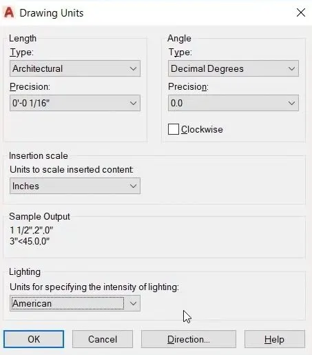
AutoCAD is now prepared for our drawing
Keep Grid active and snap deactive
Uncheck the dynamic input
STEP 2
Draw the plan of building as per the specifications of the drawing
Type REC on the command prompt and specify any point at the screen
Give the dimension as 25"*35'
Press Enter.
Type Offset in the command prompt keeping distance 9"
Select the rectangle and offset at 9" inwards
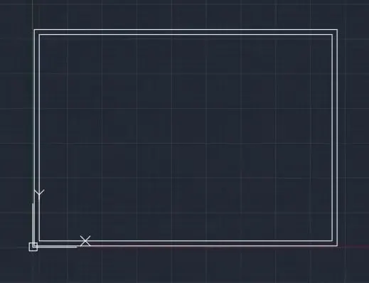
Type EXplode in the command prompt and select the outer rectangle.
Draw all internal walls using offseting command by specifying distance.
CREATING 3D WALLS
Click the home icon next to view cube
Now select presspull from the modelling panel and click inside the area to get the 3D walls giving a height of 10'
Press Enter
STEP 3
CREATING CURTAIN WALLS, DOORS AND WINDOWS:
Go to the front view to make the cutouts
The plane showing is X-Z plane but AutoCAD doesnt make drawings in X-Z plane. So for changing it to X-Y plane,go to the coordinates panel>click on dropdown>select view
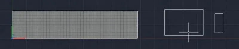
Type REC
Specify a point and dimensions 14'-3" x 9'-6"
Make another rectangle for doors as 3' x 7'
Make another rectangle for windows as 3'x 4'
Click on home to change the view
Change to the UCS WORLD view and right click on view cube>parallel
Click extrude and select curtain wall and add a thickness 10" and enter
Extrude the door and add a thickness 5"
Extrude the windows and add a thickness 5"
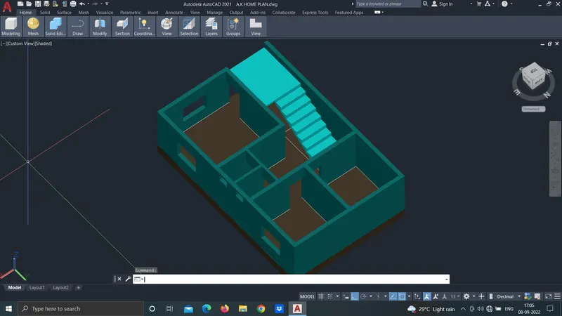
Rotate as per the requirement and place at their respective places
STEP 3:
MAKING GROOVES IN THE WALLS FOR DOORS WINDOWS AND CURTAIN WALLS
Type subtract and click the bigger wall > press enter
Click on the smaller region (door/window/curtain wall) > press enter
Groove is created
STEP 4:
MAKING ROOF, FLOOR AND ETTIC
Go to surface> planer
Click on two extreames for the floor
FOR THE ROOF
Select Rectangle and on the top of the walls create a rectangle
Select offset giving a distance 1' select the rectangle
Create the offset on the outer side
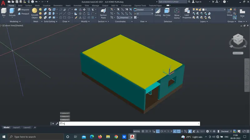
Go to presspull in the ribbon
Select the area of the polyline and presspull to a height 6"
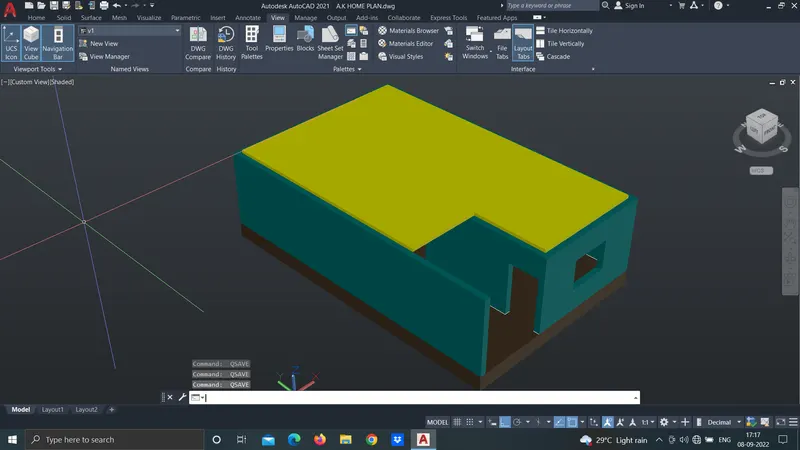
This is the height of the slab
TO CREATE A GROOVE FOR THE ENTRANCE
Type subtract and click the slab > press enter
Click on the smaller region ie the recatangle> press enter
Groove is created
CREATING ETTIC
Around this groove make a rectangle
Give the offset distance 5" inwards
Click presspull and give a height 10'
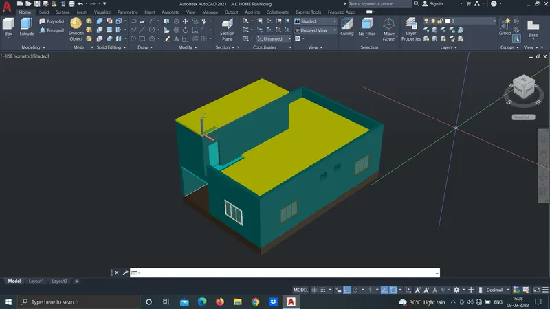
We can also add a floor layer
Go to surface> planer
Click on two extreames for the floor
STEP 5
ADDING LAYERS
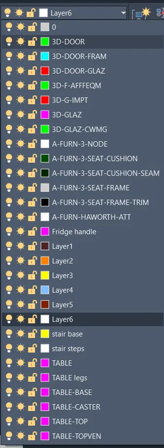
Click layer properties and and add different layers for different objects
ADDING BLOCKS
First hide objects like Surface, slab , floor ettic by clicking isolate> hide objects
Type I>enter>Browse blocks
Open the blocks as per the requirement eg door, curtain walls, TV wall, Windows, Stairs etc
Rotate as per requirement
Additionally we will use Ceiling lights
For this we just need the roof
Select the roof > right click> isolate > isolate objects
Press I> enter > browse> ceiling light
Go to the top view
Move to any point
Type ARRAY > Rectangle
No of columns - 3 No of rows 2
Increasing the distance to 10' in the column section and Increasing the distance to 5' in the row section
STEP6:
THICKENING THE SURFACE BELOW :
Click surface>enter
Add the thickness as 6"
Enter
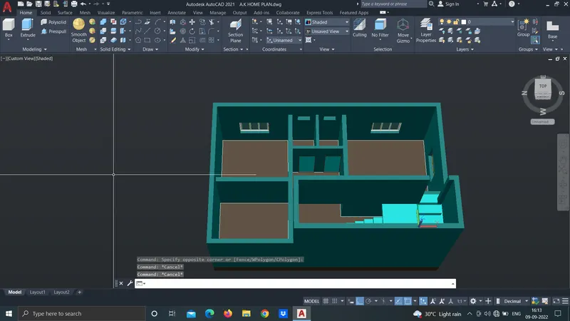
3D house is prepared now comes the visualization and rendering part
STEP 7
VISUALIZATION:
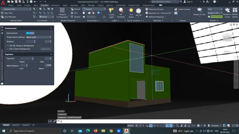
Add Camera to create view
For this we hide roof walls and surfaces by isolating them
Go to visualization> create camera>
Orbit the drawing to the specific area
Moving the direction of the camera to the walll
Now tweaking the camera to a particular view
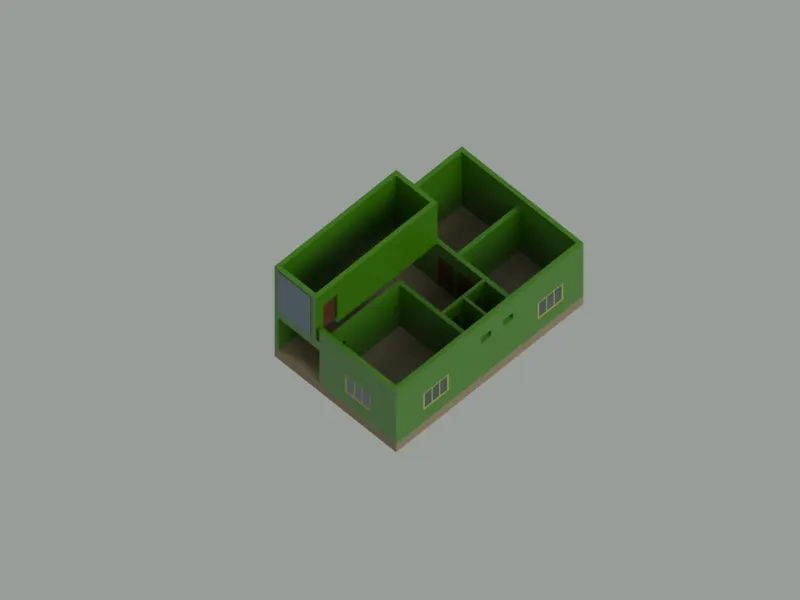
RESULT: After completion of project, I am able to make 3D model off any building.