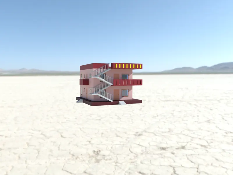
Project 2_Creating a 3D rendered model for a Residential Building in AutoCad
Introduction: Autocad is a commercial Computer Aided Design(CAD), It is marked and developed as Autodesk. It was first released on december 1982. Autocad derived from a program, which was beganed in 1977 and then released in 1979 called as Interact CAD, and also called in early documents od autocad as microCAD, Auto desk cofounder was Michael Riddle.
The first version of cad was released in december 1982 and was supported on CP/M-80 computers, By march 1986 Aotocad has became most uniquitous cad program worldwide. The file format of autocad was .dwg, and its interchange file format to DXF, have become a standard. Autocad was included support for .dwf, a format developed and promoted by Autodesk, for publishing CAD date. In year 2022 the Autocad 36th major version was released and the 12th consecutive year of Autocad foe Mac.
CAD is a technology which replaces manual drawing with automated process, if you are a drafter, desingner, architect or engineer you have been used 2D or 3D CAD programs i.e., Autocad or Autocad LT software. Autocad helps you in draft construction documentation, explore ideas for design, viaualise concepts through photorealistic renderings and gives how a design performs in real world.
Autocad mailnly used by industries, architects, engineers, city planners, project managers, graphic designers and other professionals.
Aim: To create the 3D model residential building and render it using Autocad
Steps:
1.Open new file in Autocad 2023, Type UNITS, use Decimal and take millimeters
2.Then LIMITS, Limits of lower left corner give (0,0) and limits of upper right corner (10000,10000)
3. Change the settings to 3D modelling
4. Create the following layers and if required we can add others layers as per requirement
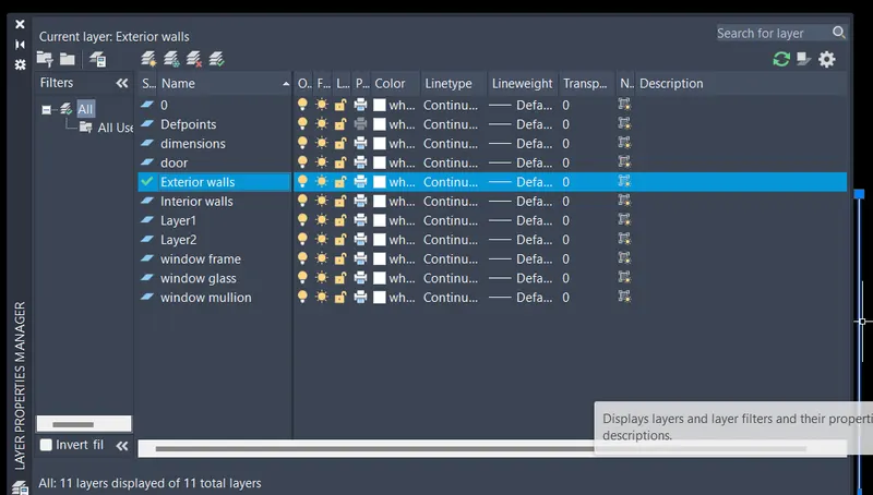
5. Set current layer as Exterior walls
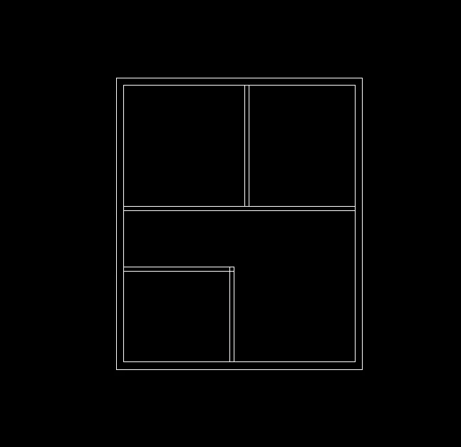
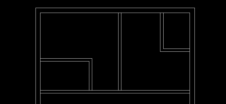
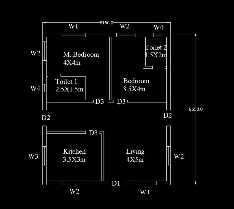
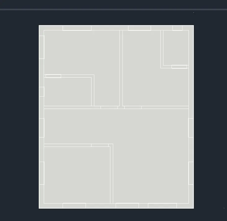
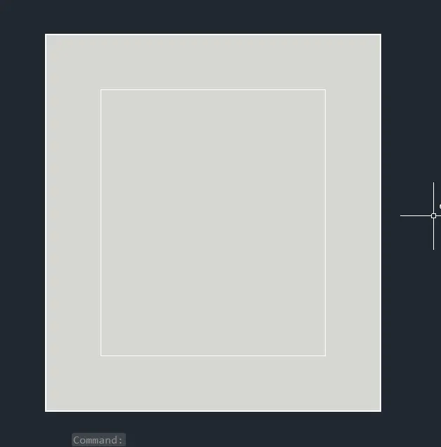
Using rectangle command, draw rectangle of size 8.15X9.65m
then offset the rectangle in inward by 250mm and explode the offsetted rectangle
Now set current layer as interior walls
Offset the bottom horizontal line by 5000 and then 150mm in upward direction
Offset the right verical line by 4000 and then 150mm in left direction
Offset the bottom horizontal line by 3000 then 150
Offset the right verical line by 3500 and then 150mm in left direction
Trim the extra lines
6. create the toilets of size
2.5X1.5m in master bed room: To create Offset the left verical line by 2500 and then 150mm in right direction and then Offset the bottom horizontal line by 1500 then 150 and trim extra lines
1.35X1.85 in guest bed room: Offset the right verical line by 1500 and then 150mm in left direction and Offset the bottom horizontal line by 2000 then 150 and trim extra lines
7. For living room:
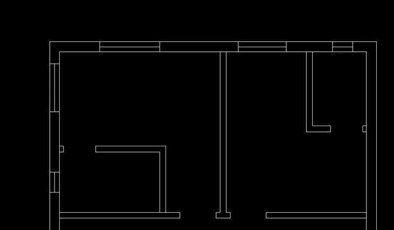
create door D1 of size 1200X2100 and window W1 of size 1500X1500 on horizontal wall of room
the door it at a distance of 150 from kitchen right wall and distance between door D1 and W1 is 500mm
create door D2 of size 1000X2100 and window W2 of size 1200X1500 on vertical wall
D2 is at 500 from the guest bed room and W2 is at 1000 from horizontal wall
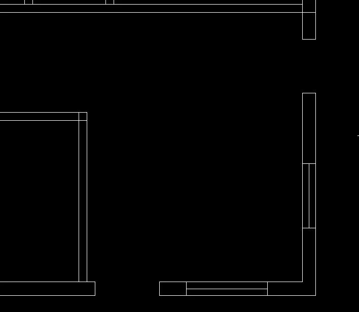
8. Door D3 of size 900X2100 is placed at opening of two bed rooms and and opention of kitchen
W1 is placed on horizontal wall of master bed room
W2 is placed at vertical wall of master room and for guest bed room
Door D4 of size 800X2100 is provided for toilets
Window W4 of size 500X700 is provided for toilets
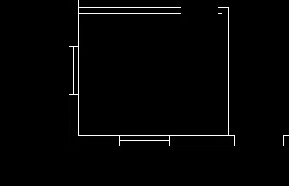
9. For kitchen door D3 is provide
And window W3 of size 1200X800
And W2 at horizontal wall
10. Set the current layer as Dimensions and provide dimension
and set current layer as text and provide Text
Ground floor plan without stair case
11. Off the dimension and text layer and change it to SW isometric view from Top view
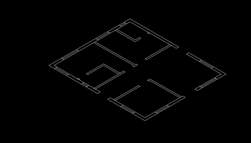
12. Using boundary make Region
Set current layer as Exterior walls and Extrude the exterior walls by 3000
Set current layer as interior and extrude it by 3000 and dont extrude at windows and doors
and provide surface at bottom of the plan using surface planar
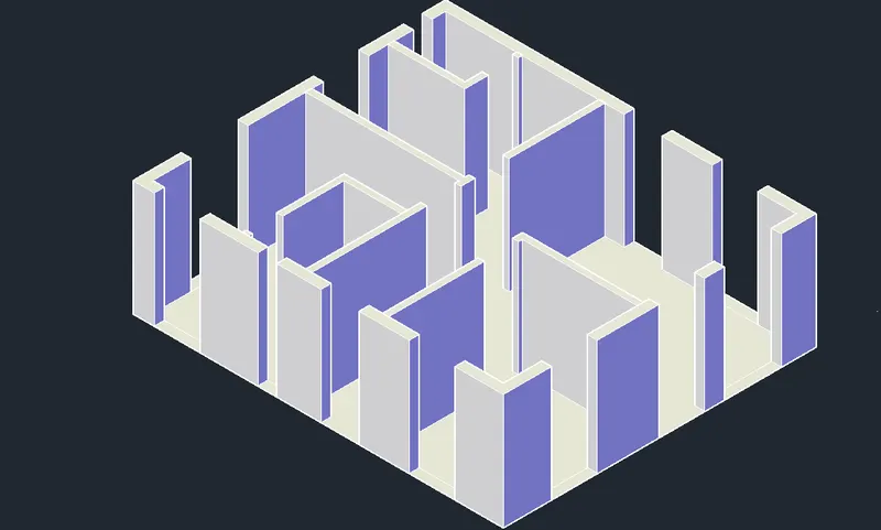
13. Extrude the W1 and W2 by 600mm i.e, the sill level provided is 600mm
and Extrude the W3 and W4 by 1300
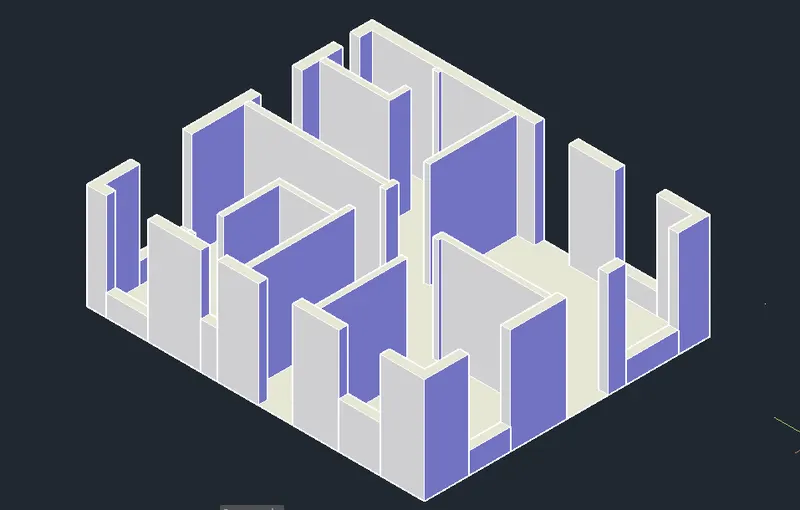
14. Draw the recrangles above the openings windows and doors
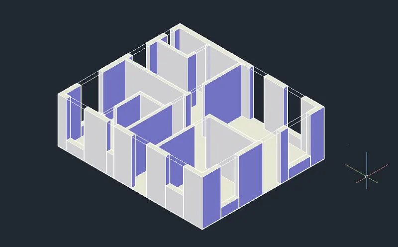
Extrude the exterior wall openings by 900 downward
setcurrent layer as Interior walls and extrude the openings by 900 downward direction
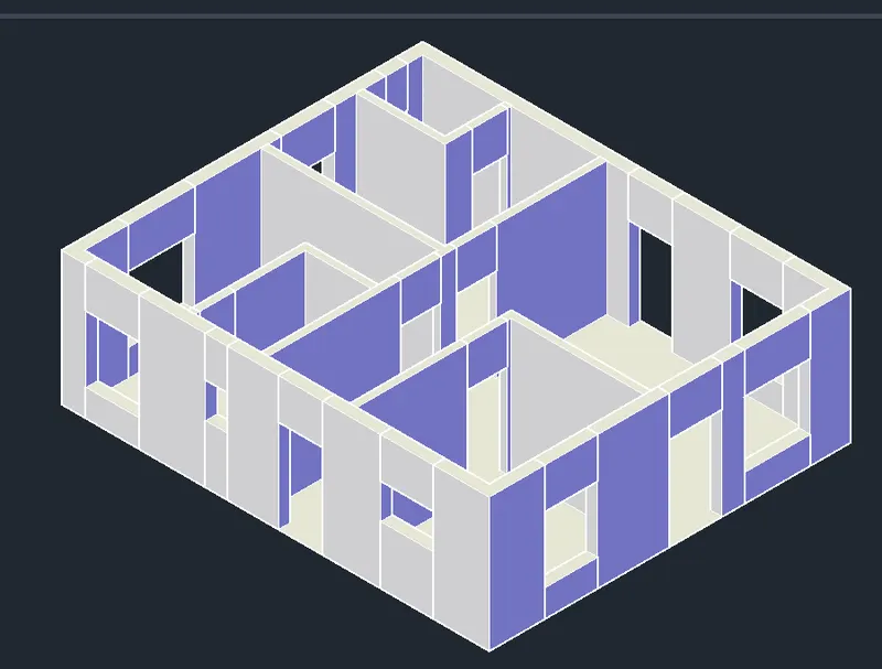
Top view
15. Select and make Union
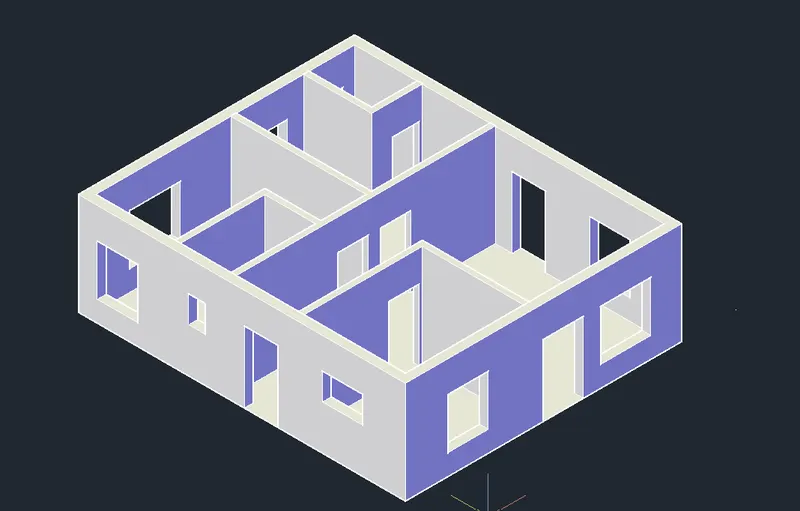
16. Create Plinth layer and select the surface and extrude it by 600 in downward direction and change the colour
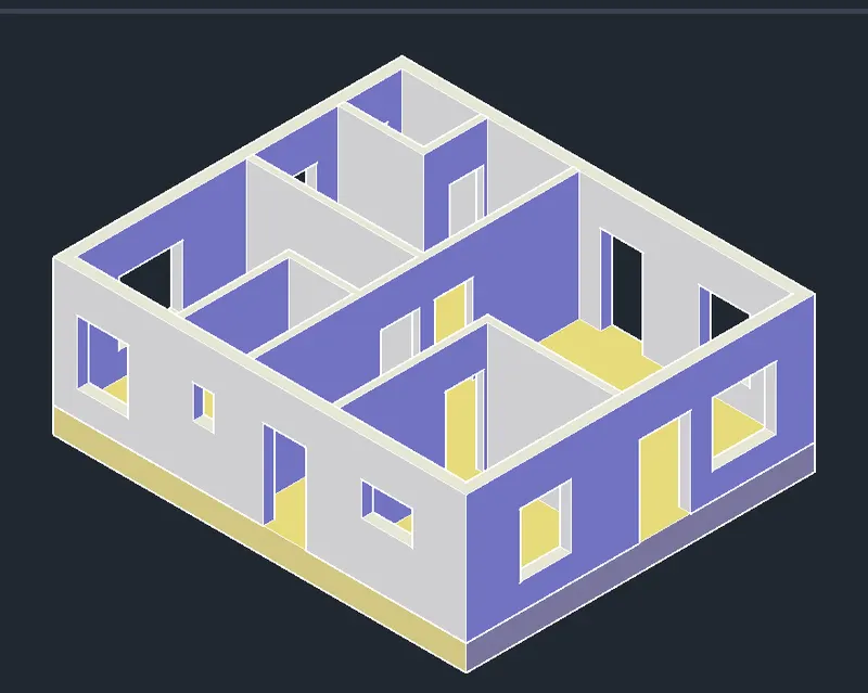
17. Creating Windows:
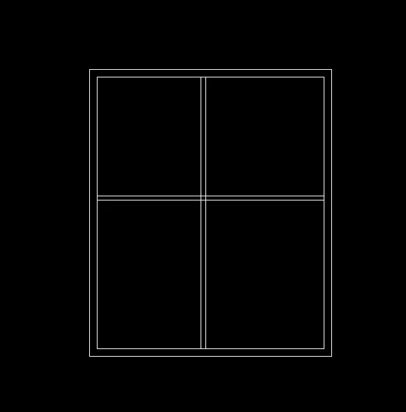
To creat a window W1 set current layer as Window frame and draw 1500x1500 and change layer to window mullion and offset it by 75 inward direction
change layer to glass and offset it by 50 and draw mid vertical line and offset on both sides and trim extra lines
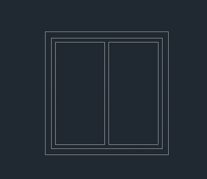
Make the regions of window frame, window mullion and window glass separetely and give different colours in layers
first region window frame by using command Boundary and subtract the remaining two
then region window mullion and subtract the glass
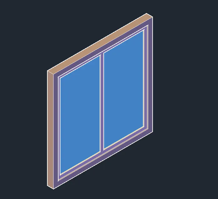
extrude window frame by 100 and mullion by 70 and glass by 15 and move as per required
Move the mullion by 15 backward and the move the glass by 30
Front view of W1:
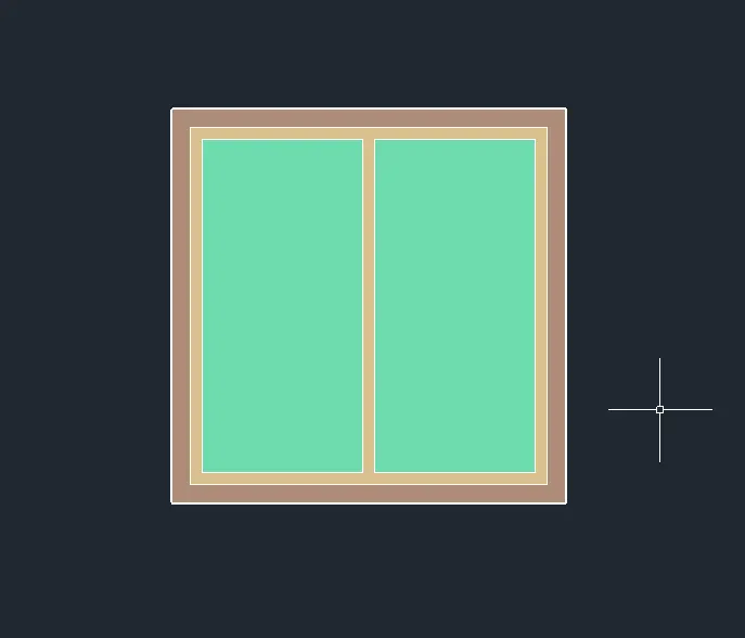
SW view of W1:
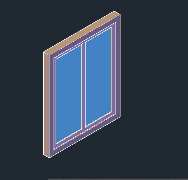
Similarly draw and extrude W2, size is 1200X1500
Front View of W2:
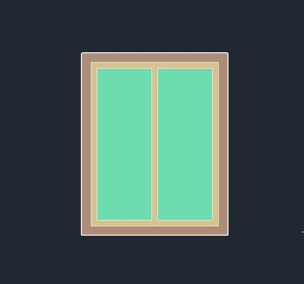
SW view of W2:
draw and extrude W3, size is 1200X800
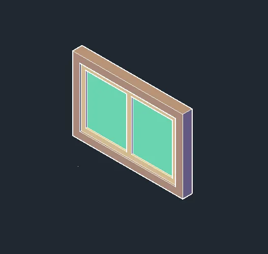
Change to Left View, and create W3:
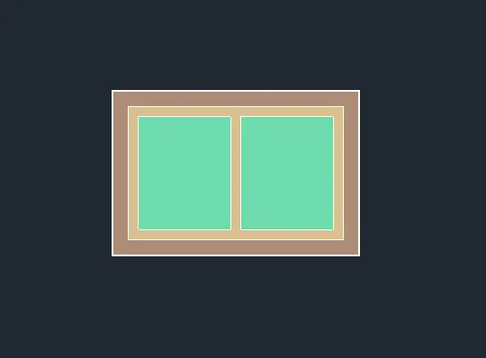
SW view of W3:
draw and extrude W4, size is 500X800
Change to Left view, and create W4:
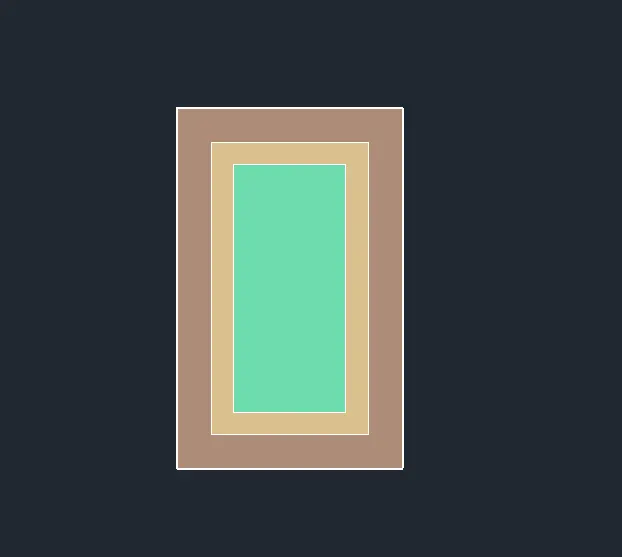
SW view of W4:
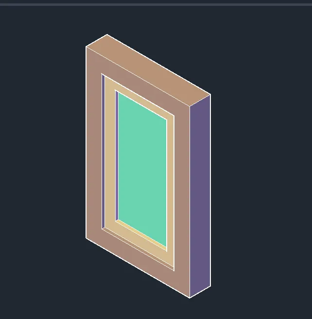
18. Make the windows as Blocks and name the blocks as W1, W2, W3, W4
the insert and rotate the windows as per required
copy and place them at required positions
SW view of Residential building after placing windows:
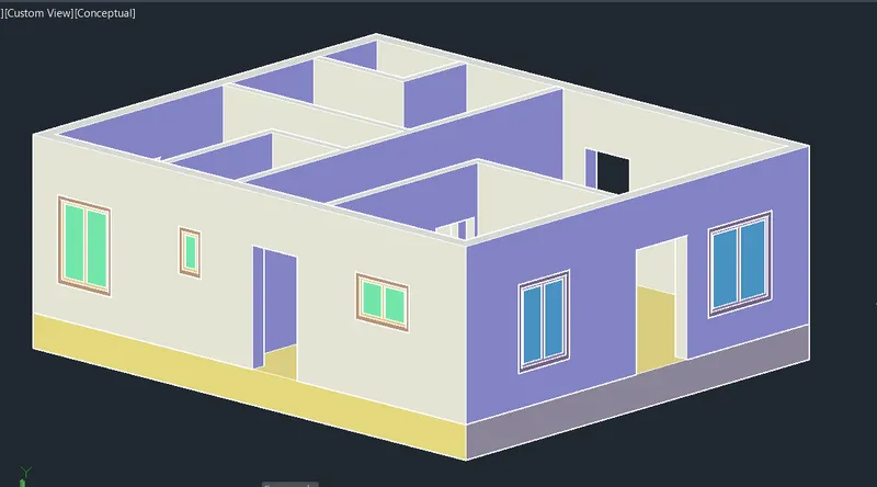
NW view:
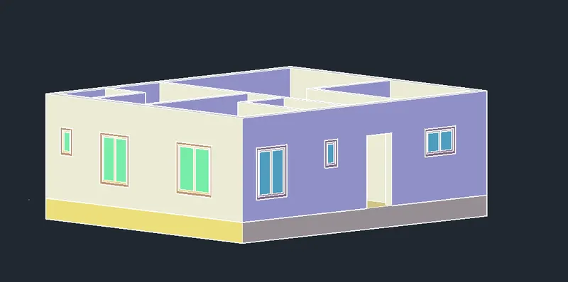
SE view:
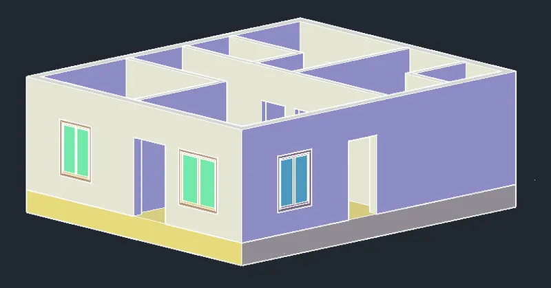
19. Create Doors:
To create main door D1 of size 1200X2100
Change current layer to Doors and keep it in front view, use rectangle and draw 1200X2100 and Extrude it by 50
Draw a sphere to show the handle of the door
Make it as Block and name the door as D1
Front view:
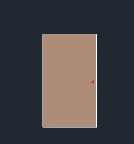
SW view:
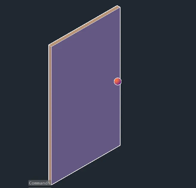
Similarly create the door D2 of size 1000x2100 by changing to left view
and make it as block
Left view:
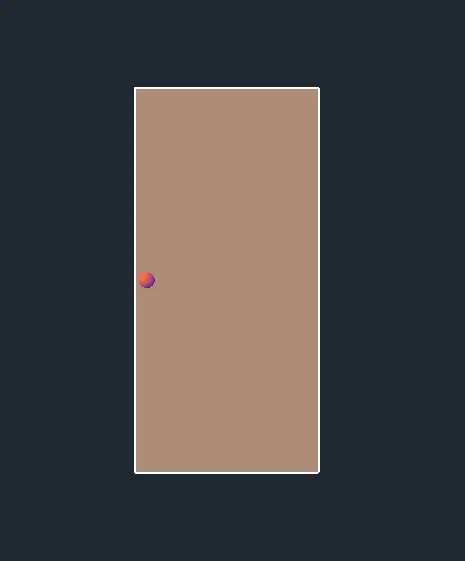
SW isometric view:
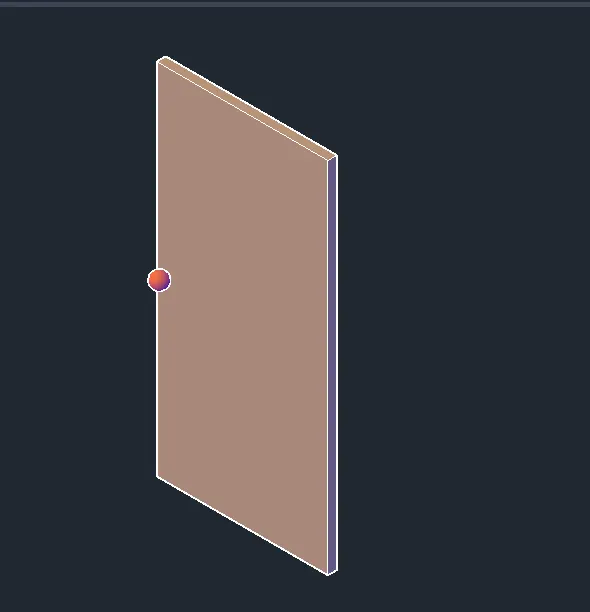
D3: size 900X2100 change to Fronyt view and draw and make it as block
Front view:
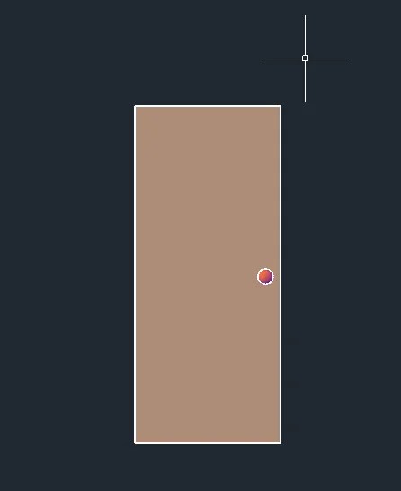
SW view:
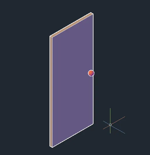
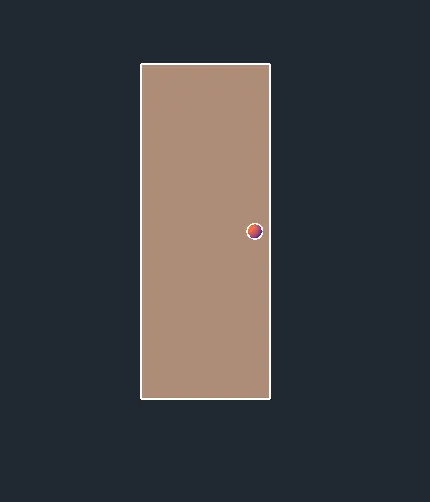
D4: size 800X2100 change to Fronyt view and draw and make it as block
Front view:
SW view:
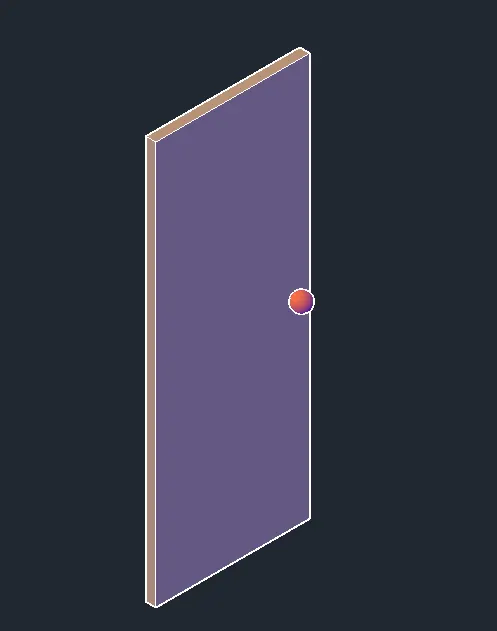
20. Placing of doors
Select the doors and copy to required places and use rotate 3D command and place accordingly
To place interior door Off the exterior wall layer and place
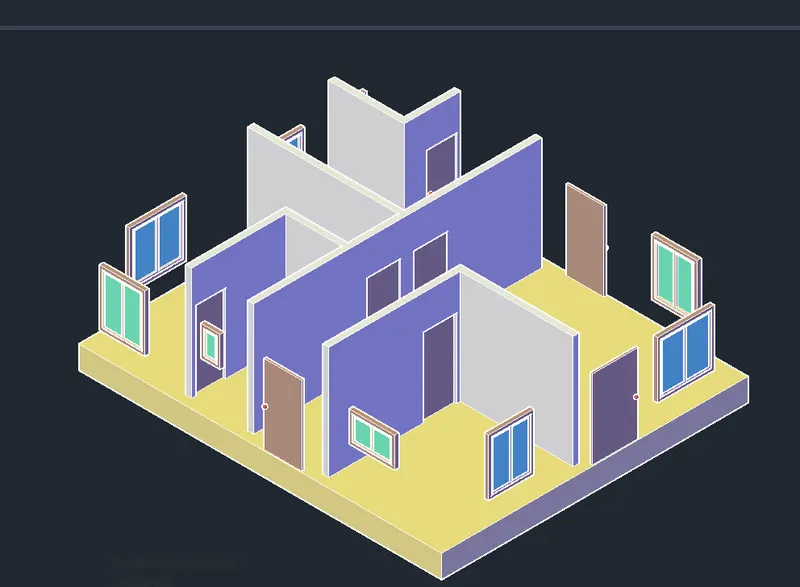
After placing Doors
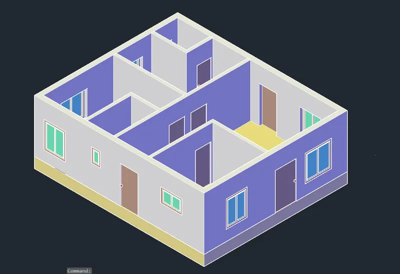
21. Opening for Kitchen: For architectural purpose and for our convinent
Off external wall, windows and doors layers
Create a rectangle by keep ucs at right bottom corner and give co-ordinates as (300,1000) and (1900,1100)
Then extrude it by 150
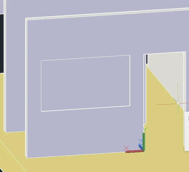
Use Subtract and remove the rectangle portion
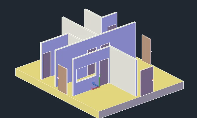
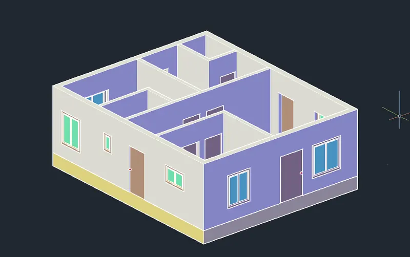
22. Create the slab layer, and set current layer
Draw the rectangle on top of ground floor connecting interior points
and offset it upward by 150
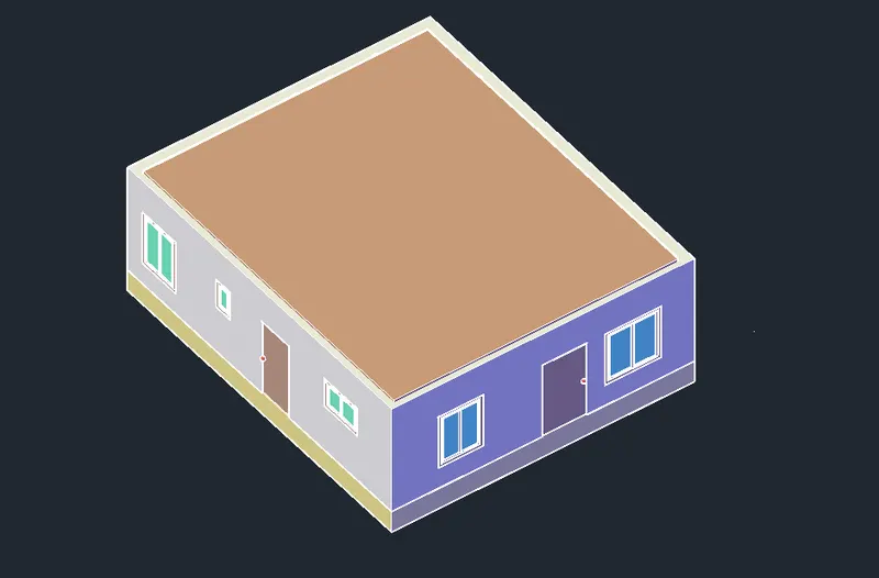
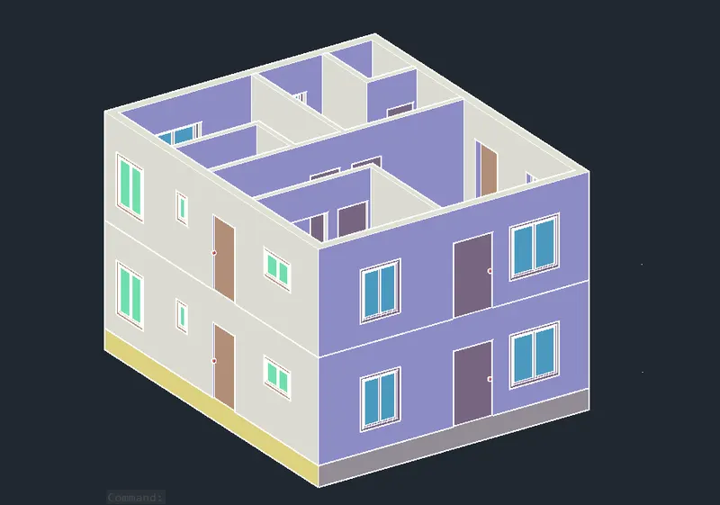
23. Copy the ground floor all walls, windows and doors and place it above, so First floor is created
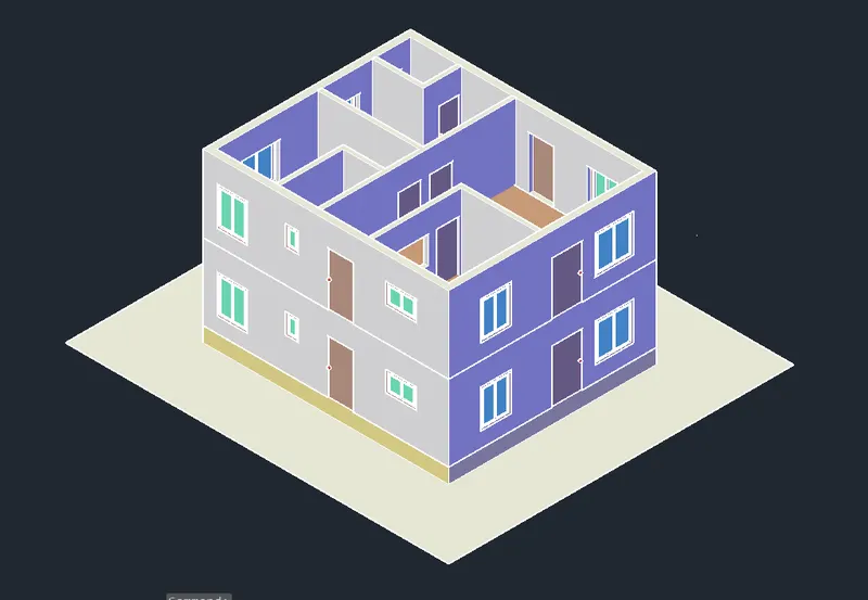
24. Create Ground level
Take the outer line of the building and offset by 2700 outward direction and make planar surface
and place it below the plinth
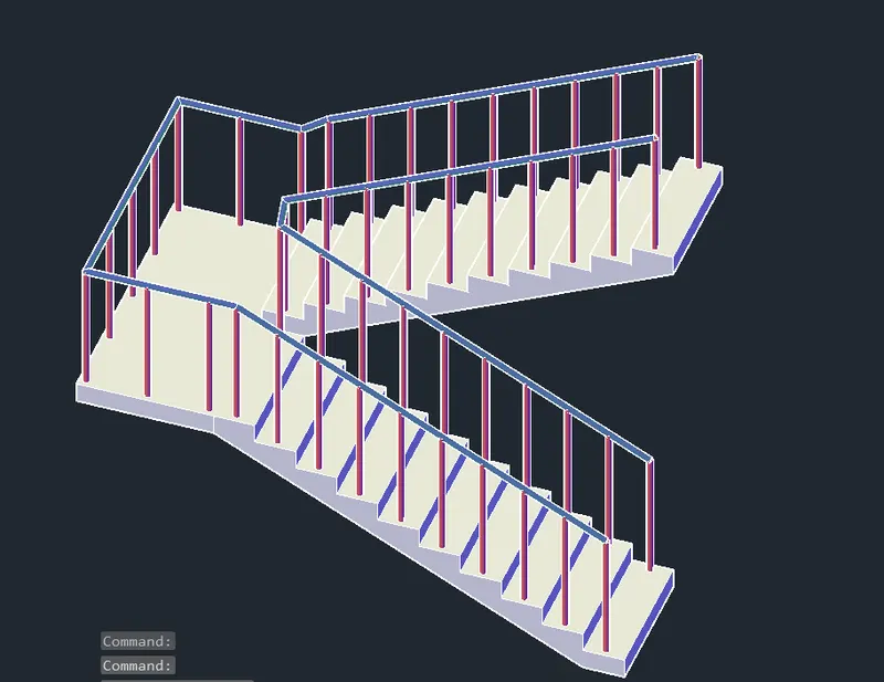
25. To create Stair case
Draw 150 rise and 300mm thread
Copy and array the step for 10 times andjoin the steps
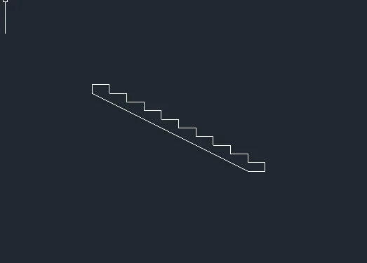
Make region and Extrude it by 1000mm
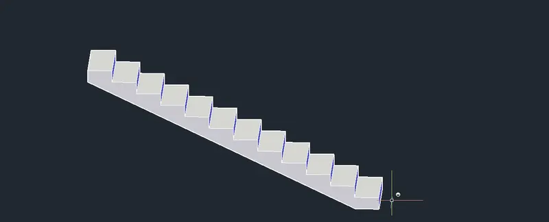
Change the layer to Stair baluster
and draw a circle at 50mm from thread
and Extrude it by 1000
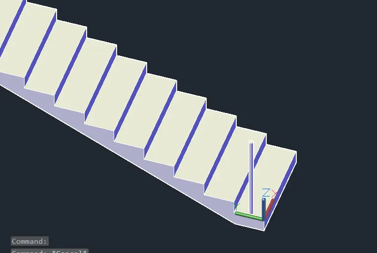
Using Mirror and copy place the balusters for every step
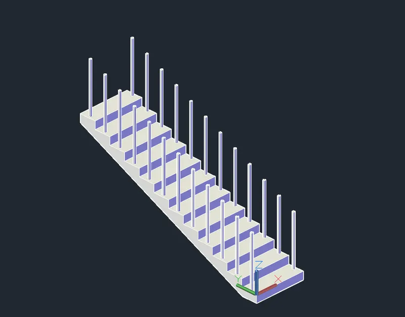
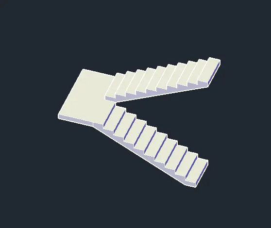
Off the baluster layer and draw the rectangle of 2000X1000 and extrude it by 150 and place it as landing
Copy the steps on other side and
provide baluster for landing
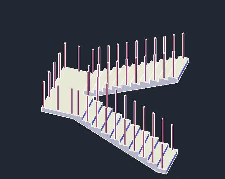
Change layer to hand railing
Using 3D polyline join the center points of baluster and draw circle of radius 20 at staring and Sweep the circle along the path, so that hand railing is created
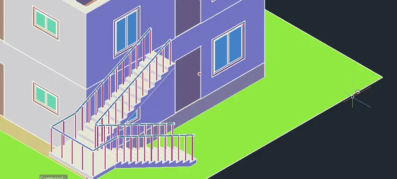
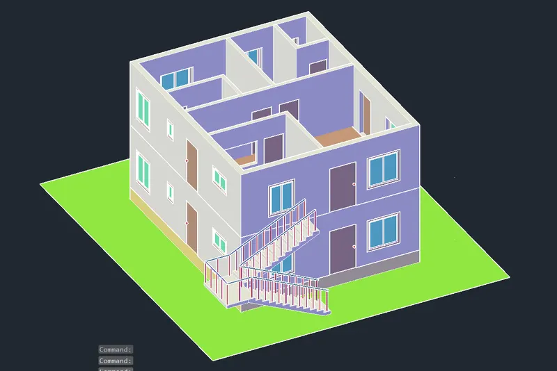
26. Place the stair case from a distance of 1000mm from the door
give baluster and railing different colour
And given for ground level green colour
27. To create Balcony
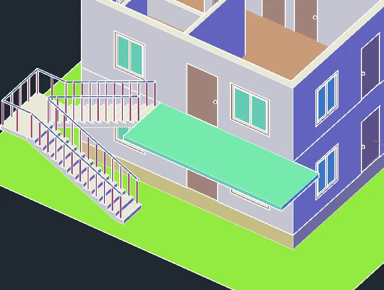
draw a rectangle of size 6100X150, starts from the stair case
And extrude it by 2000
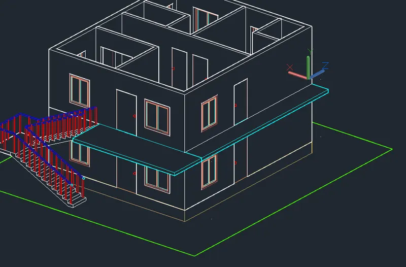
Draw the rectangle of 9650X150 on other side below the door
and Extrude it by 1000
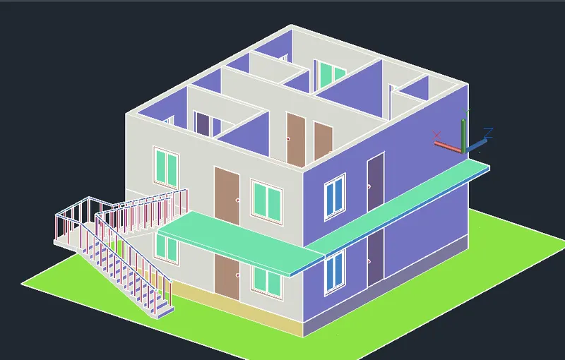
Change to Left view and create balcony for door, draw the rectangle 2400X150 and extrude by 1200
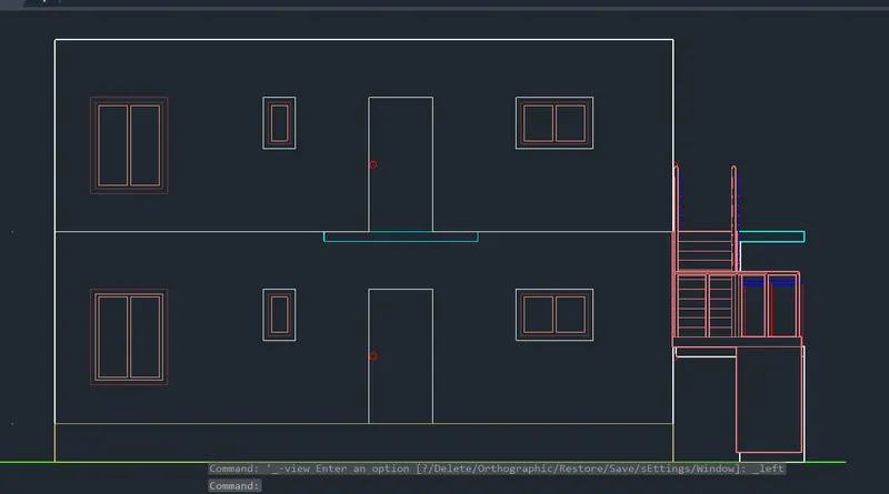
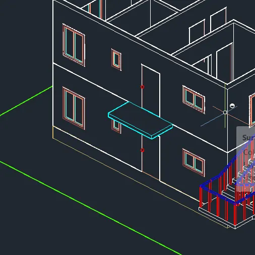
Front view:
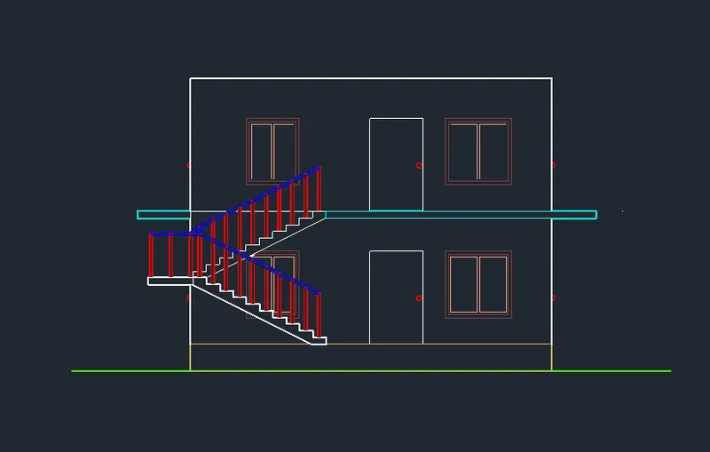
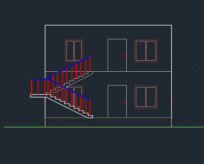
28. Copy the stair case and paste it for first floor
Front view:
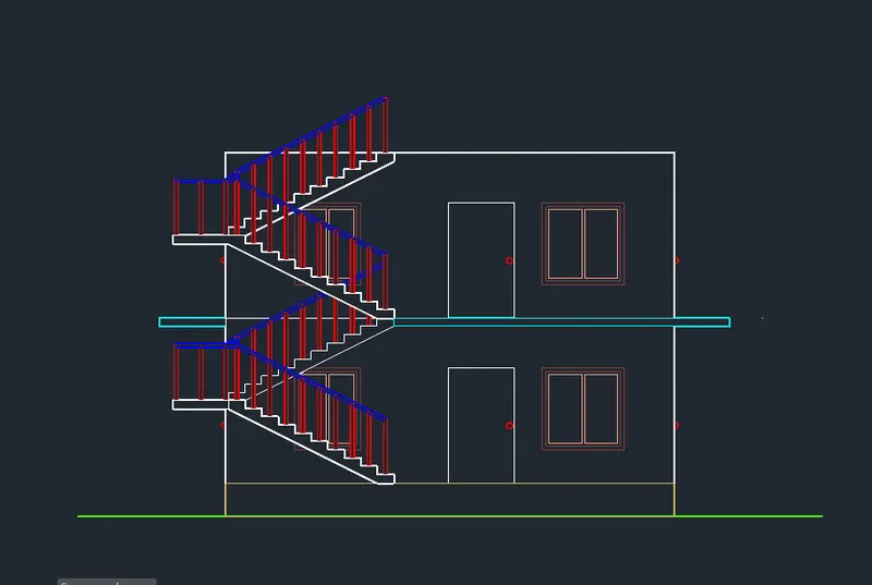
SW view:
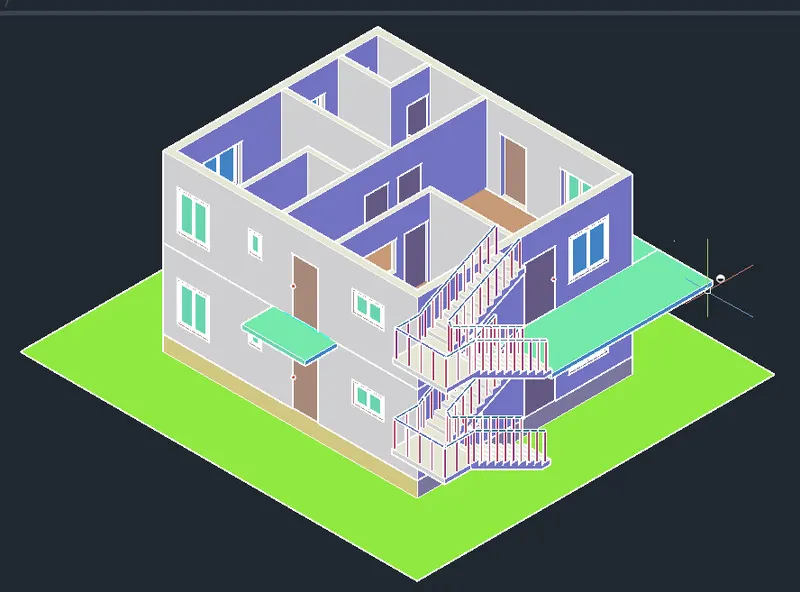
SE view
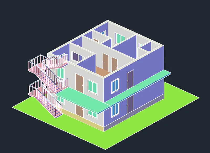
29. Draw the wall for Balcony of height 1000 and thickness 100
draw rectangle of width 6100 and height 1000 and extrude it by 100
and draw rectangle of width 11700X1000 and extrude by 100
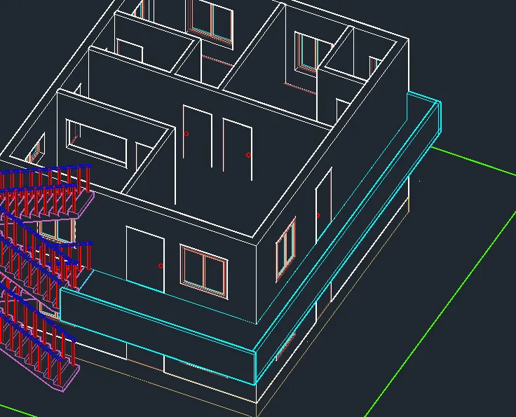
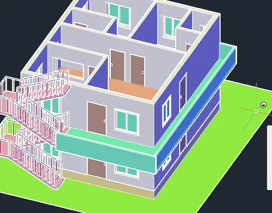
draw rectangle of height 1000 and extrude by 100
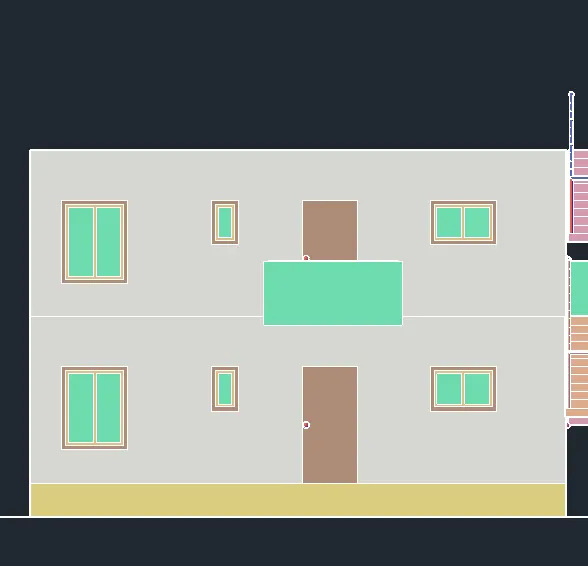
Select the balcony walls and make it Union
SW view
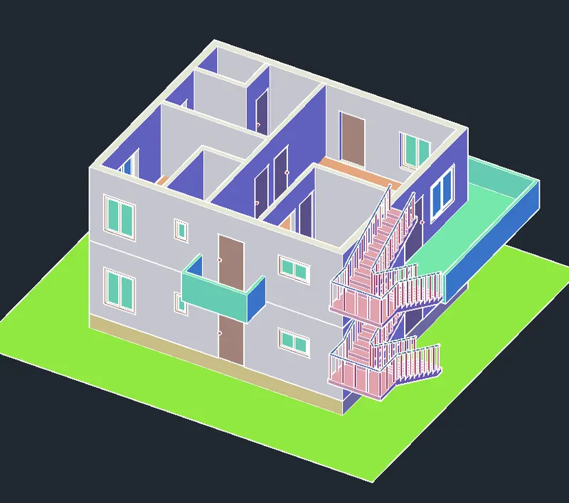
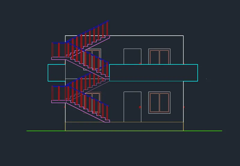
Front view of balcony hidden
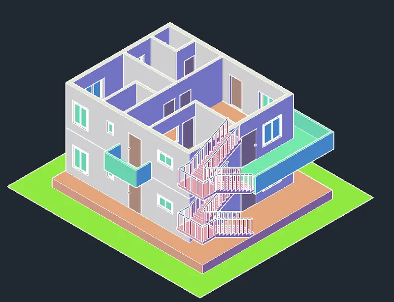
30. Draw the wall upto Plinth height, that is at a distance of 1000 from left and right walls
and 2050 from the front wall and back side 50
SW view
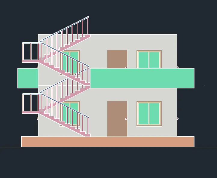
Front view
31. Change the layer to slab and provide slab of 150mm on first floor
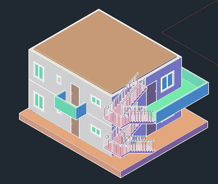
32. To get the Parapet wall
change to Top view and draw the required boundary of parapet wall using 3d polyline
and select the parapet wall plan and move
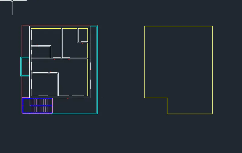
copy the boundary again
One make region and extrude by 150 upward
and another one Offset it by 100 inward and using Presspull extrude it by 1000
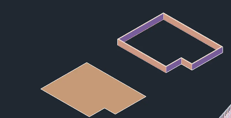
Copy the parapet wall and place it over slab and make Union
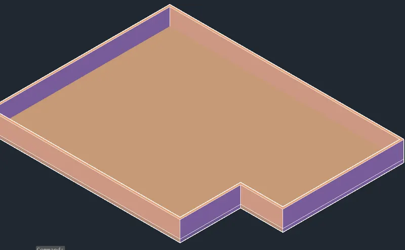
SW view:
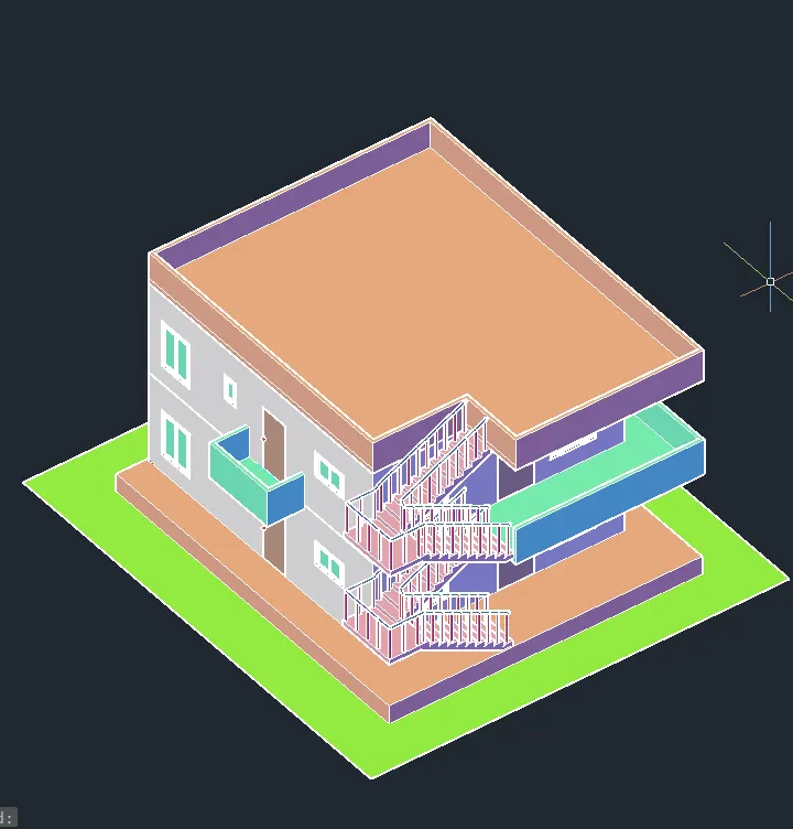
Draw a rectangle for the opening after steps and extrude by 100
then using Subtract command remove that part
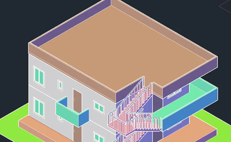
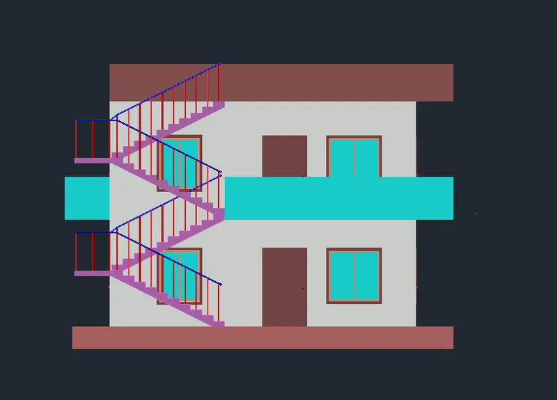
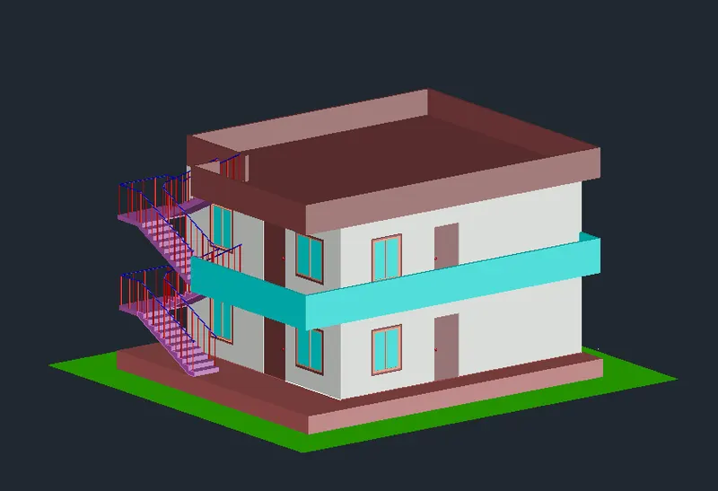
Front view in Realistic:
SW view:
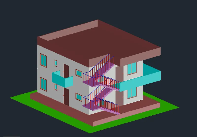
SE view:
34. To create the steps and plinth level
Set current layer as stairs
draw a rectangle of 1000X600 and explode
Offset the bottom line by 150 upward 3 times
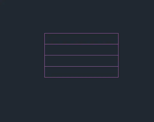
using Presspull extrude the steps by 300,600,900 and 1200 from top to down
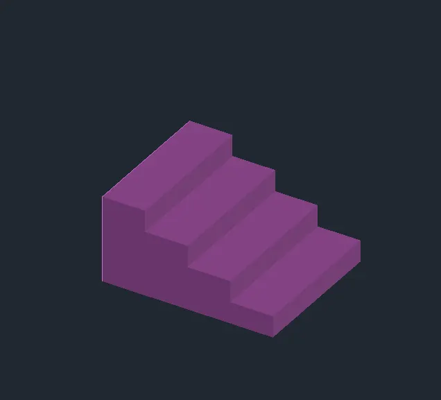
Place the steps before the doors
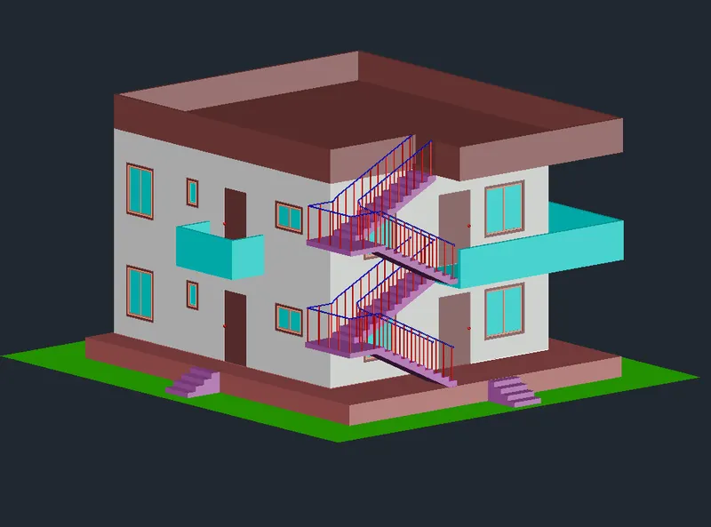
35. View of Residential drawing before materials assigning:
SW view:
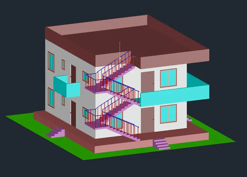
SE view:
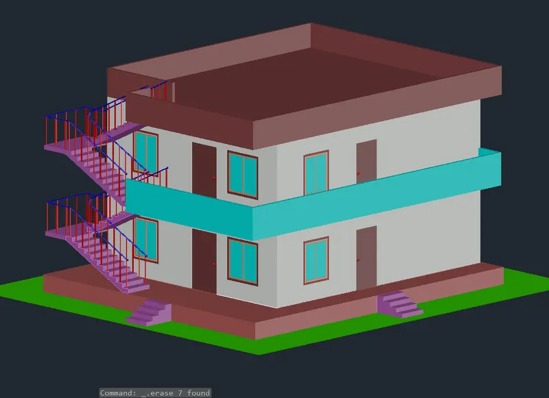
NE view:
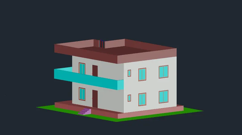
NW view:
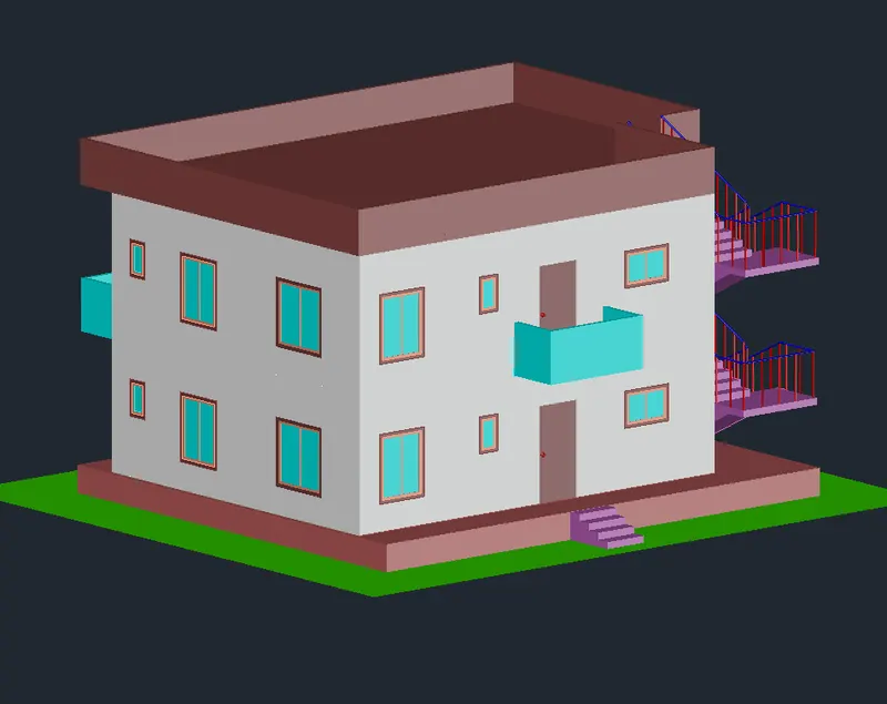
Front view or Elevation:
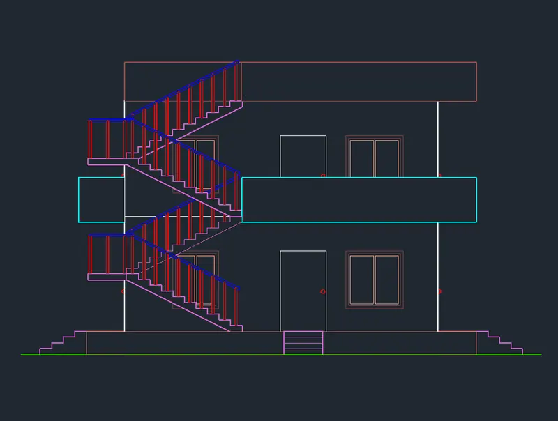
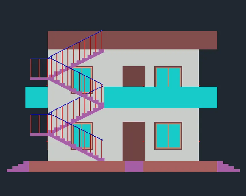
36. Assiging materials:
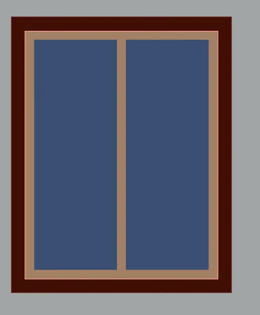
For windows, assign Blue reflection glass for glass, Cherry type wood for mullion and colobolo wood type for frame
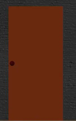
Assign the door as Teak wood and door handle as Anodized red metal material
Assign Stairs as Flat groom gray concrete and for balusters and hand railing Steel polished
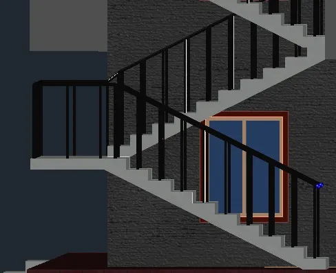
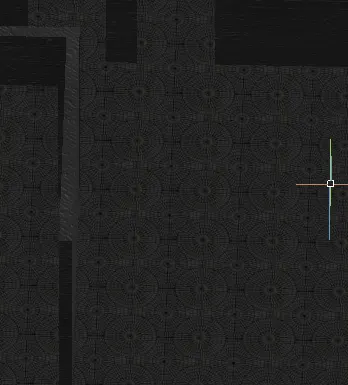
For flooring assign Circular mossaic fllor tile, off exterwall layer and assign material
Assign Concrete for External walls and for internal walls
masonary for balcony and parapet
and brick masonary for plinth height wall
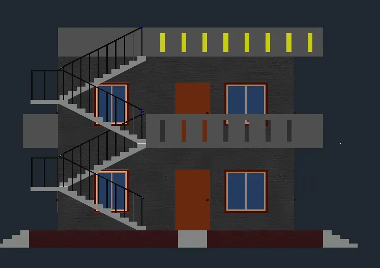
SW view:
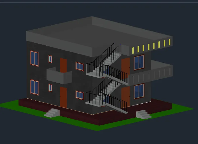
SE view:
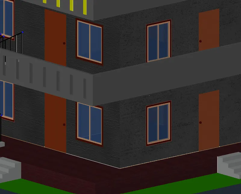
37. Provide Cameras and lights at required
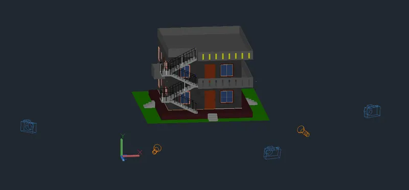
Picture of Camera 1:
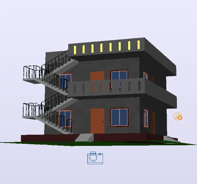
Picture of Camera 2:
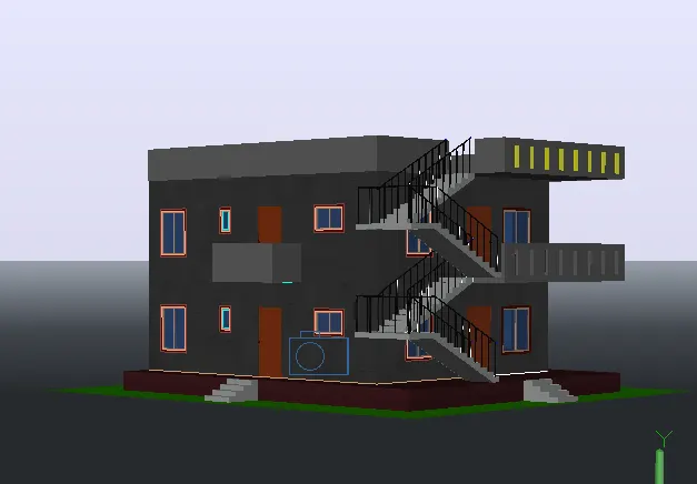
Picture of Camera 3:
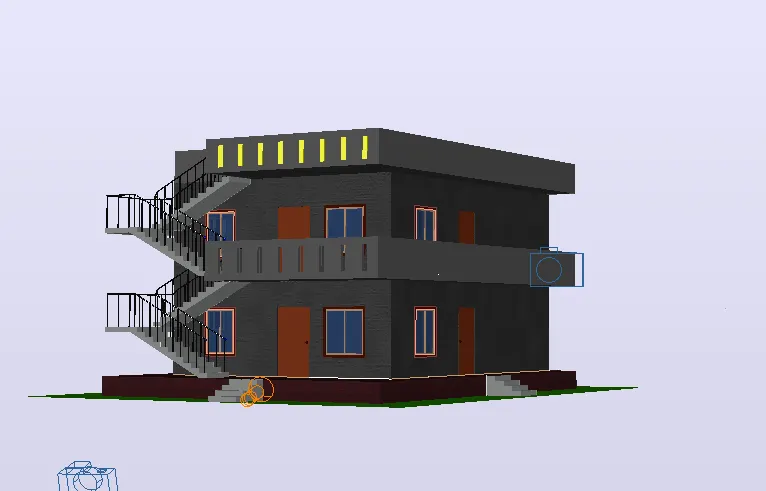
38. Change the Environment
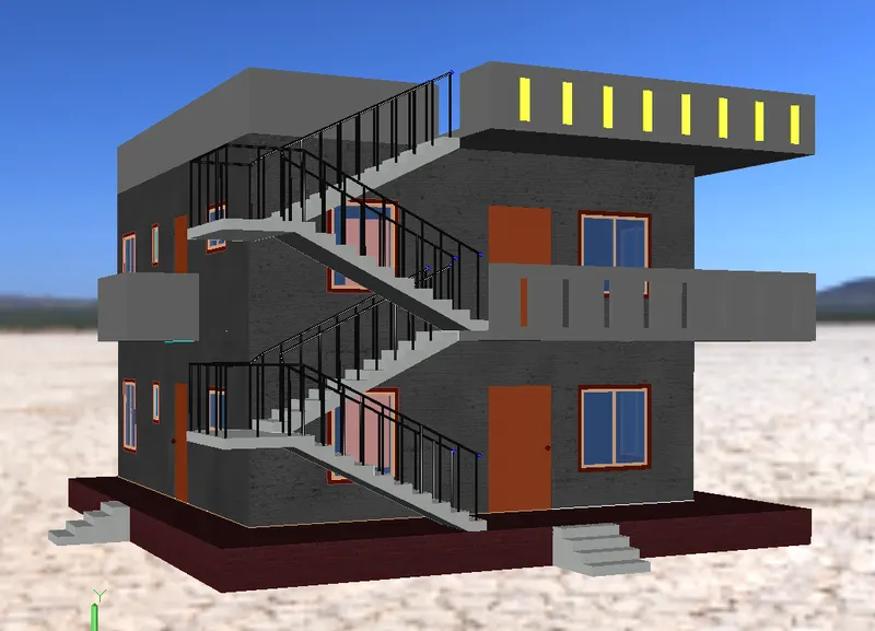
Rendered image:
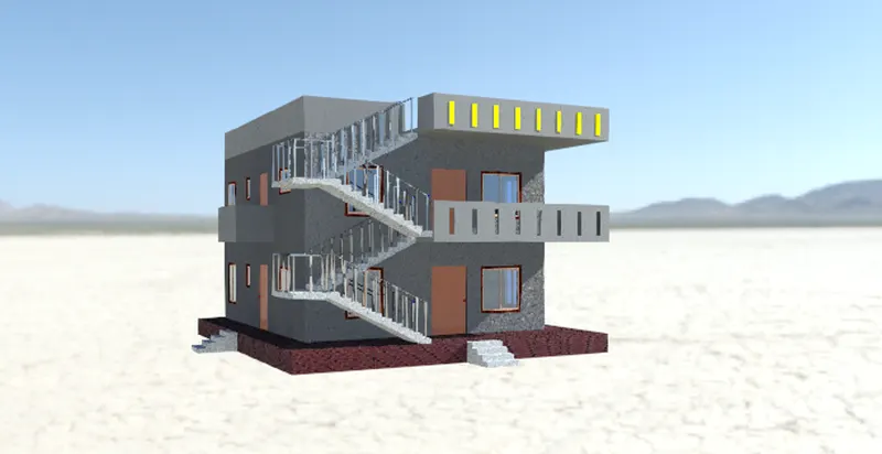
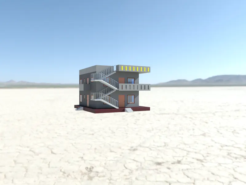
39. Changing the materials:
Give wall painting to some elements
For interior walls Slate blue
For exterior walls pearl
For parapet and balcony assign Chest nut
Remaining materials are same
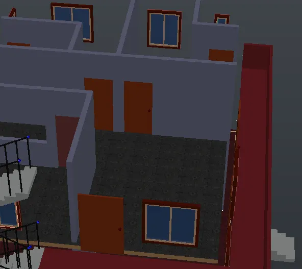
SW view:
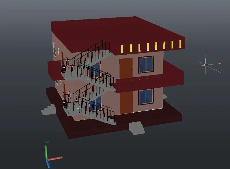
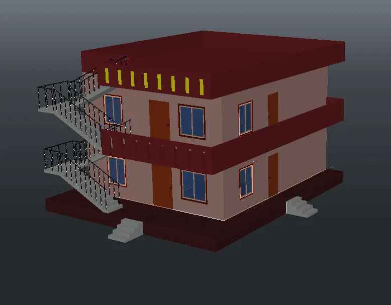
SE view:
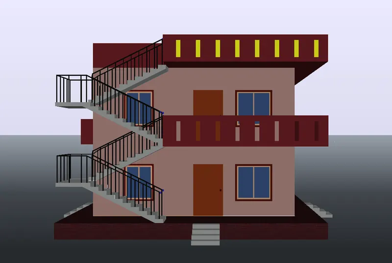
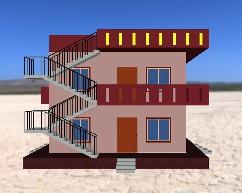
Elevation:
40. Change environment to dry river bed
SW view:
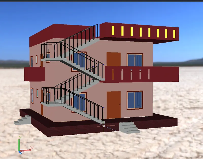
SE view:

NE view:
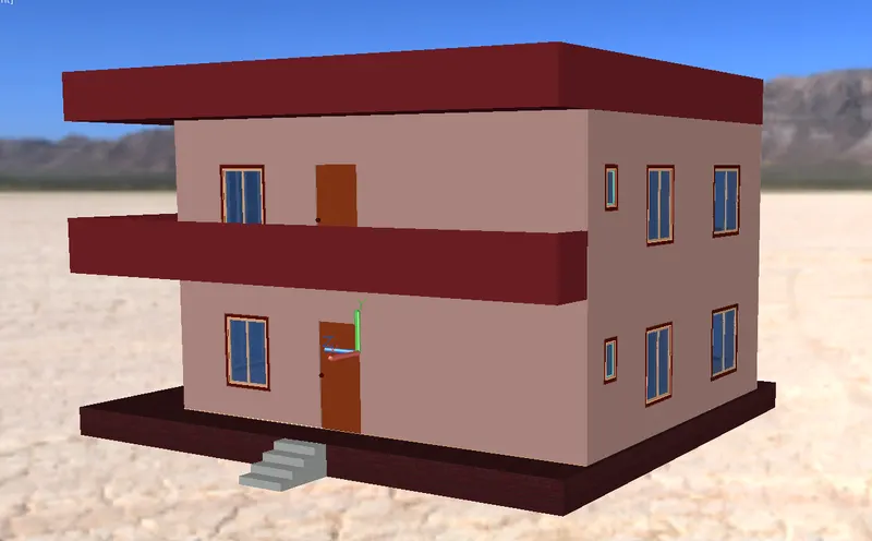
NW view:
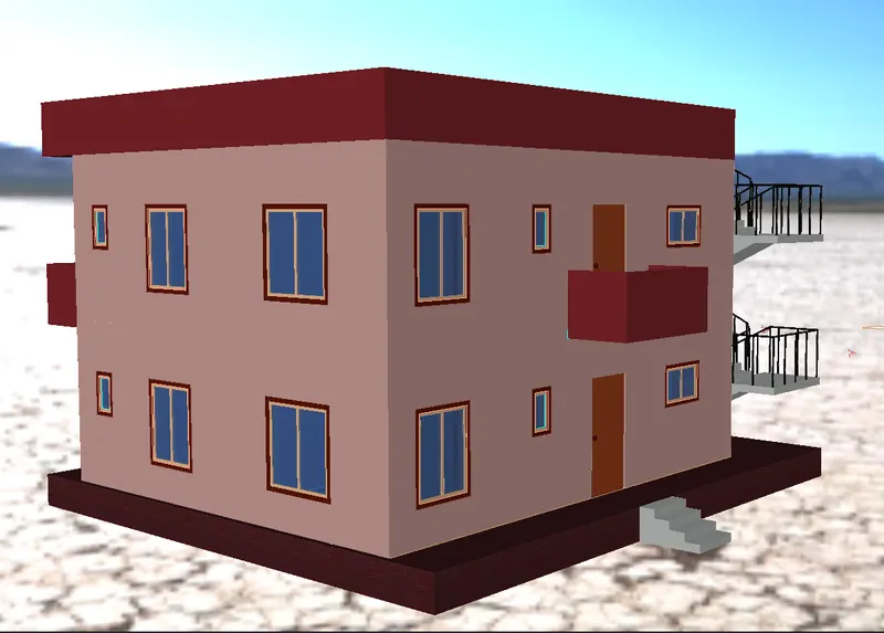
Elevation:
Results:
Rendered image:
Rendered image with wall paints: