Project 2_Creating a 3D rendered model for a Residential Building in AutoCad
Aim: To Create a 3 dimensional model of the residential building with a rendered view.
Introduction: The adopted design consists of area of 25 x 45 feet. Imperial system is adopted in this drawing. The plan consists of two bedroom,Kitchen, a large living and dining hall and also a parking space at the front. It is also considered as G+1 residential plan model. The height of floor to floor is taken as 10'. External and internal walls are taken as 9" and 4.5" respectively. Height of the plinth is taken as 4' and a ramp is also provided for vehicle entry into the building.
Steps:
a.) creation of plan:
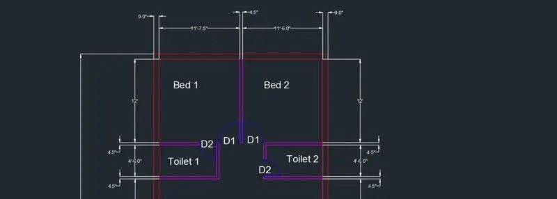
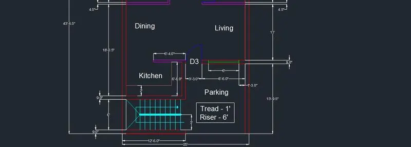
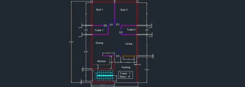
- For creating the plan top view is fixed and other settings such as units,limits are set.
- Then using xline command two lines are drawn one in vertical and another in horizontal and the intersection point is fixed as left edge of the plan.
- Then using the trim command the unwanted lines are trimmed off.
- Furthermore using offset command thickness of wall is provided and offset is done in both horizontal and vertical directions to create the proposed plan
- The plan which starts at the left edge finishes at the right edge and the extra lines are trimmed off using the trim command
- The dimensions of offset depends on the wall thickness and dimensions of the room as adopted.
- Stairs are provided at the left corner of the plan for accesibility between the floors
- For providing stairs line command is used and the lines are drawn at a distance of 1' which is the tread of the stairs.
- Windows are provided with sizes of 6' x 4' and 3' x 4' respectively and are drawn using the rectangle command and copied and placed in the rooms accordingly.
- Then layers are defined from the layer properties panel such as external walls, internal walls, windows etc., and are assigned to the created plan.
- Finally after defining dimension style dimensions are marked by using dimlinear and dimcotinue command.
b.) Creation of elevation:

- For creating elevation projection lines are drawn from the created plan using the xline command in the vertical direction
- A line is drawn using the line command in the horizontal direction which sets the bottom edge of the elevation figure
- Then using the offset command the drawn in line is offsetted at a distance 10' and the offset is repeated to provide 2 floors and the last line is offsetted at a distance of 3' to provide parapet wall at the top of the building.
- For window creation a rectangle of 6'x 4' is drawn using the rectangle command
- Then the created rectangle is offsetted at a distance of 2" inside
- A line is drawn at the middle of the inside rectangle using line command and again offset is done at a distance of 2" and the extra lines are trimmed using trim command to provide two inner rectangles on either sides of the straight line which is the glass of the window.
- For doors a rectangle of 3' x 7' using rectangle command and a offset of 2" is done
- Then the created windows are copied and placed in the diagram at the sill level 3' of each floors.
- The doors are placed at each floor level and the elevation is created.
c.) Creation of 3d structure:
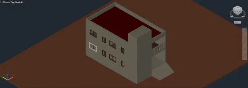
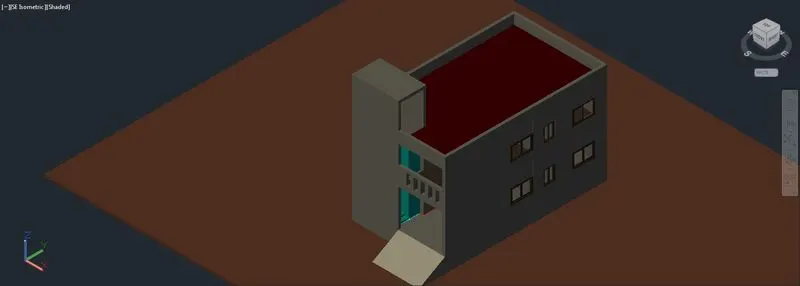
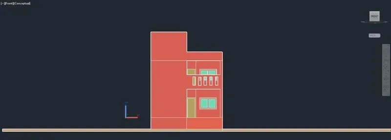
- For creation of the super structure in 3d initially the default 3d isometric view is fixed and the created plan is copied
- Then using the boundary command regions are created except the windows i.e., the walls only
- Then using extrude command the walls are extruded to a height of 10'
- Then rectangles are drawn using rectangle command at the gap between the walls i.e., the windows at the top and bottom
- The rectangles are drawn by keeping the ucs in the face wherever required by ucs command and face option
- The bottom rectangle is extruded in +Z direction to a height of 3'
- The top rectangle is extruded in -Z direction to a distance of 4' which leaves the gap 4' between them so as to place windows
- Then using union command all of them are joined to become one single unit.
- Then for windows creation the winows created at the elevation figure is copied and it is edited
- Using boundary command regions are created such as frame, mullian and glass and each region is subtracted from the bigger region using subtract command
- Then using the extrude command the regions are extruded to distance of 5"
- layers are defined from the layer properties panel such as glass,frame and mullian and are assigned to the windows
- Then the windows are copied and placed in the gaps left for windows in the created 3d structure
- To provide windows in various parts 3d rotate command is used to align the wndows as per the requirement.
- Doors are also created like the window creation and are placed in the 3d drawing
- Then a rectangle is drawn at the top of the created ground floor structure and extruded to a distance of 6" which is the slab or first floor level of the building
- Then the created ground floor structure is copied and placed at the first floor level
- A wall is created in front by drawing a rectangle and extruding to a height of 5' and rectangles are drawn at the face of the created wall and using subtract command they are subtracted from the wall face to provide a aesthetic design in wall at the 1st floor structure which forms a balcony area in the first floor
- Then again in the plan regions are created by boundary command and extruded to height of 3' for providing parapet wall
- The head room region at the stairs are extruded to height of 10' and using union command both are joined and placed at top of the created super structure by using move command and the structure is created
- To provide plinth level of 4' a large rectangle of plan size is drawn and extruded using extrude command of 4' in -Z direction and placed at the bottom of the structure
- Then ramp is provided by drawing a triangle using line command and extrusion is done.
- Layers are assigned to the created structure and the 3d structure is created and finished.
d.) Rendering:
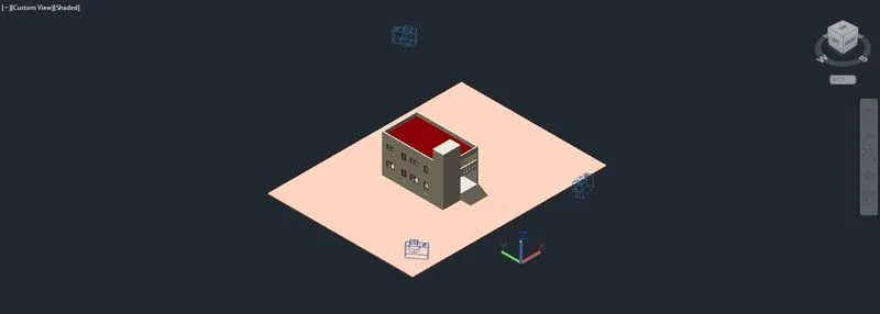
- For renering purpose cameras are placed as per the requirement of the view
- The cameras are created by drawing a circle and extruded to a certain height and the cameras are placed at top of the created circles and after placeing they are deleted.
- The cameras are named , target and lens are adopted during the placement of cameras
- Then from the material browser materials such as wall paint, flooring, roofing , window and door frames and glasses are assigned to the created building. They are adopted roughly to provide aesthetics to the building.
- Then lights are fixed as per requirement from create light option in the ribbon. In this case distant lights are provided.
- Finally after presettings like render quality etc., rendering is done using the render command.
- There rendering images are done and provided.
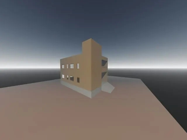
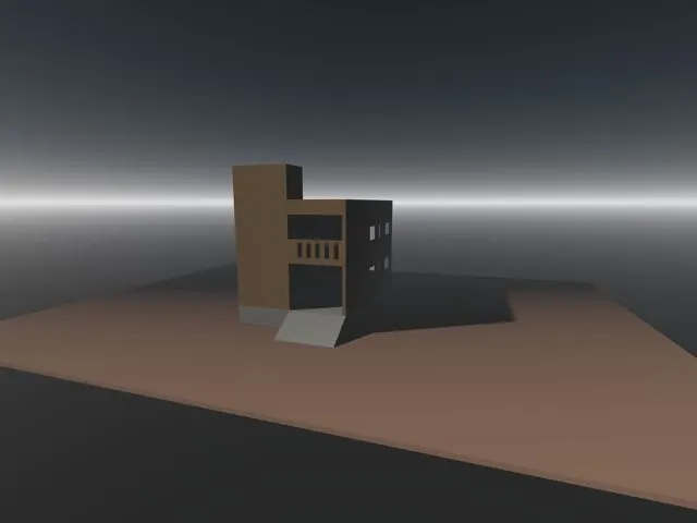
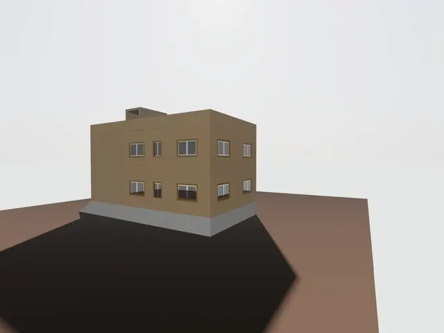
Results: A residential plan of 2 bedroom G+1 is created and elevation figure is created and creation of 3d structure and rendering of the same is done sucessfully.