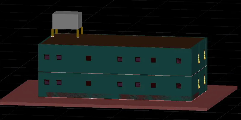
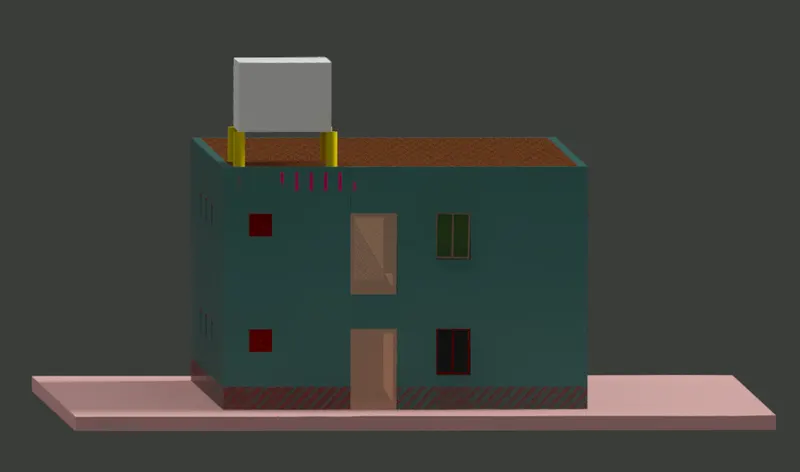
Project 2_Creating a 3D rendered model for a Residential Building in AutoCad
AIM:
Creating a 3D rendered model for a Residential Building in AutoCad
INTRODUCTION:
The main objective of the project is to create a plan in 2D & convert it into 3D then applying materials & rendering
AutoCAD is used by AEC(Architecture, Engineer, and Construction) to generate and optimize 2D and 3D designs. AutoCAD is a widely used software program that can help you draft construction documentation, explore design ideas, visualize concepts through photorealistic renderings, and simulate how a design performs in the real world. (Autodesk)
Basic 2D Commands:
To execute an AutoCAD command, type the command (or quick-key) in the command line. The command line is located at the bottom of the drawing area. Some commands require additional steps, or subcommands, the next step for the command will be displayed in the command line.
- LINE and POLYLINE – The LINE (L) and POLYLINE (PL) commands are some of the most used commands in AutoCAD; however, each command is uniquely different than the other. For instance, the LINE command will only draw a series of line segments. Once the command has been completed, each segment is its own object. POLYLINES, on the other hand, can be lines or curves. And when the command has been completed all segments are joined together. In Microvellum, polylines are used for a variety of commands and options. It is a good practice to use the POLYLINE command versus the LINE command.
- ARC – The ARC (A) command will allow you to create an arc by selecting a start point, second point, and endpoint. You can also specify a start point, center point, and endpoint. Or, you can specify the start point and endpoint and then enter a radius.
- RECTANGLE – The RECTANGLE (REC) command requires you to pick a base point and then pick the opposite corner. There is an option to enter the dimensions of the rectangle as well. If entering dimensions, a third click is required to “lock” the placement of the rectangle as it will rotate around the base point.
- CIRCLE – The CIRCLE (C) command requires you to pick the center point and then specify a radius (or diameter).
- DIMLINEAR – The DIMLINEAR (DD) command will create a linear dimension either horizontally or vertically. It requires a start point, endpoint, and a point away from the baseline for spacing the dimension. Note: DD will change the layer to the 2D_DIM layer.
- DIMALIGN – The DIMALIGN (DIMALI) command, will create a dimension aligned to an object on an angle. This also requires a start point, endpoint, and a distance away from the baseline.
- MLEADER – The MLEADER (MLD) command will create a leader line, based on selected points, and open up the text interface allowing you to type a description.
- MTEXT – The MTEXT (MT) command will create a text box with multiple lines.
- TEXT – The TEXT command will allow you to create single-line text objects.
- MOVE – The MOVE (M) command will allow you to move selected objects. After selecting the object(s), you will need to specify a base point and then specify the point of placement.
- COPY – The COPY (CO) command will allow you to copy selected objects. Like the move command, you will need to specify a base point and point of placement.
- ROTATE – The ROTATE (RO) command will allow you to rotate selected objects. You will be required to choose a base point and rotation angle (or use the reference option).
- ERASE – The ERASE (E) command will allow you to erase selected objects. The DEL key will also allow you to delete selected objects.
- MIRROR – The MIRROR (MI) command will allow you to mirror selected objects. You will be required to choose a base point and secondary point representing the mirror line.
- OFFSET – The OFFSET (O) command will allow you to offset an object by a specified distance.
- TRIM – The TRIM (TR) command will allow you to trim (cut) lines or other 2D objects where they may intersect another 2D object.
- EXTEND – The EXTEND (EX) command will allow you to extend a line, polyline, or arc to the nearest intersection of another object.
- SCALE – The SCALE (SC) command will allow you to enlarge or decrease the size of an object based on a scale factor. You will be required to specify a base point and factor (you may also reference a length and enter a new length).
- STRETCH – The STRETCH command will allow you to stretch points of an object. To stretch points, you will be required to use the “select crossing” window to select the points. After the points have been selected, move them in the desired direction, and specify a distance.
- CHAMFER – The CHAMFER (CHA) command will allow creating a bevel or chamfer between two intersecting or adjoining lines. You will be required to specify a distance away for each segment, or you may specify an angle.
- FILLET – The FILLET (F) command will allow you to create a radius cut between intersecting or adjoining lines. You can also use FILLET to join two non-perpendicular lines to create a sharp corner between 2 entities if the radius is 0.
- PICKSTYLE – PICKSTYLE is a variable that can be turned on or off (1 or 0). If PICKSTYLE is on, it will allow all objects that belong to a group to be selected. With PICKSTYLE off, individual objects in a group can be selected. This can be toggled quickly using CTRL + H.
- ISOLATE OBJECTS – The ISOLATE OBJECTS (ISO) command will allow only the selected objects to be visible. ISOLATE OBJECTS also works for 3D objects. Using this with PICKSTYLE turned on is helpful to isolate an entire Microvellum product.
- HIDE OBJECTS – The HIDE OBJECTS (HIDEO) command will allow the selected objects to be hidden (opposite of ISOLATE OBJECTS). HIDE OBJECTS also works for 3D objects. Using this with PICKSTYLE turned on is helpful to isolate an entire Microvellum product.
- UNISOLATE OBJECTS – The UNISOLATE OBJECTS (UNISO) command will allow you to make all hidden objects visible.
3D AutoCAD Commands
Below is a list of commonly used AutoCAD commands that are used when working with 3D solids.
- POLYLINE (PL) – The POLYLINE command will allow you to create a 2D polyline. When working with the Solid Model Tools, it is crucial to close a polyline when trying to make a shape. Not closing a polyline will result in a mesh object being created. Mesh objects are not recognized by the Solid Model Tools.
- EXTRUDE (EXT) – The EXTRUDE command will extrude a 2D object into a 3D object. When using the EXTRUDE command, the original 2D object will be removed from the drawing.
- PRESSPULL (PRESS) – The PRESSPULL command will extrude a 2D object into a 3D object, or extend a 3D surface. When using the PRESSPULL command with a 2D object, the 2D object will remain in the drawing.
- BOX – The BOX command will allow you to create a 3D box by selecting 3 points in the X, Y, and Z axes.
- 3DMOVE (3M) – The 3DMOVE command will allow you to move an object in either the X, Y, or Z-axis.
- 3DROTATE (3R) – The 3DROTATE command will allow you to rotate an object about the X, Y, or Z axes.
- 3DPOLYLINE (3DPOLY) – The 3DPOLYLINE command will allow you to create a polyline with points that can exist in the X, Y, and Z axes.
- UNION (UNI) – The UNION command will allow you to join separate 3D objects into one.
- SUBTRACT (SU) – The SUBTRACT command will allow you to subtract 3D objects from another 3D object.
- SLICE (SL) – The SLICE command will allow you to create a joint through a 3D solid.
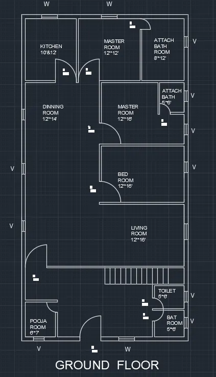
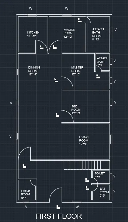
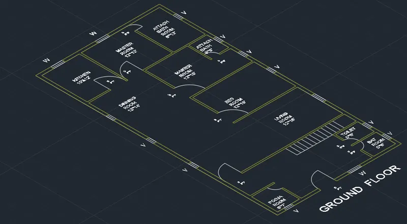
Now type extrude the walls to a height of 10'
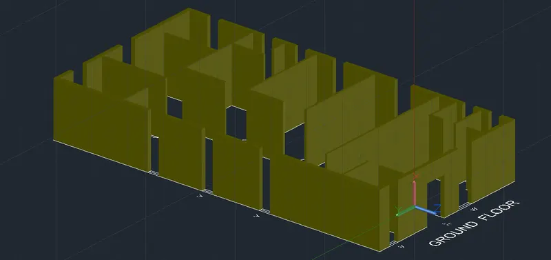
Windows & ventilators are created to the recommended sizes & placed in proper position
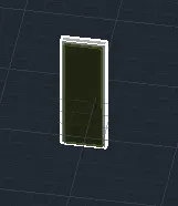
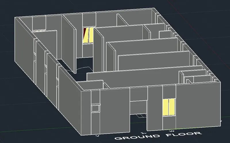 Doors are created & placed in proper position
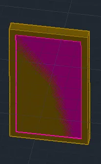
Plinth is created
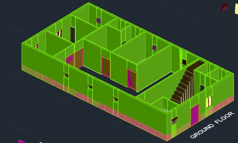
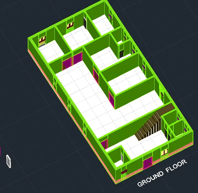
The floor level is completed
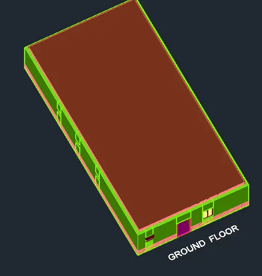
Create the ceiling over the ground floor
Now ground floor is copy & pasted the first floor is created
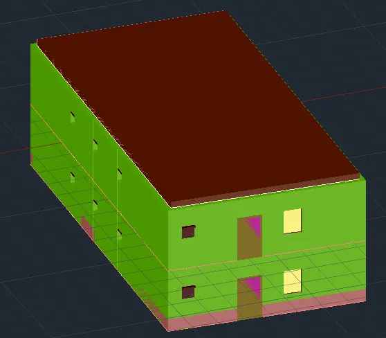
Ceiling of first floor is created & parapet wall is created using rectangle,extrude & subtract command
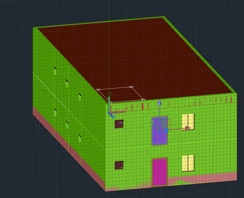
Overhead tank is created using circle ,rectangle & extrude command
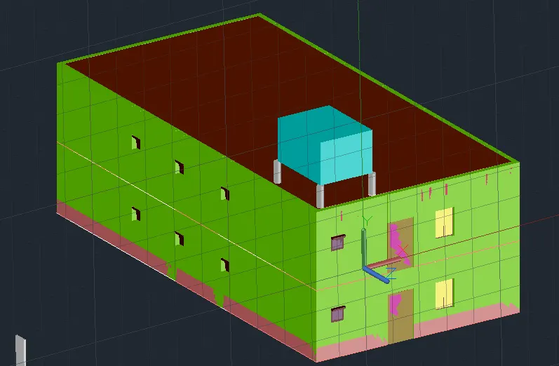
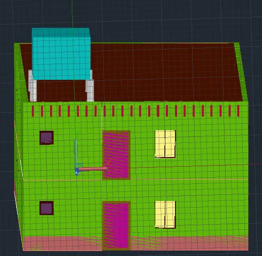
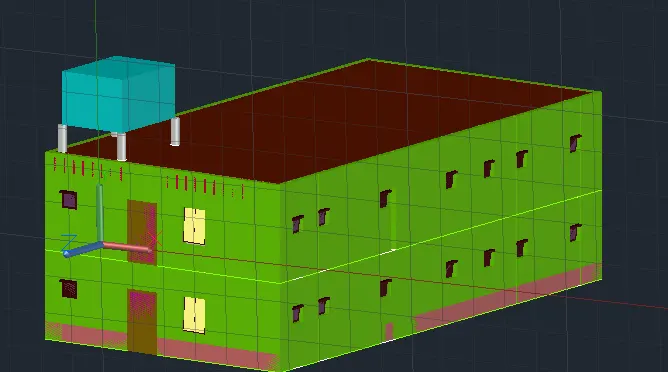
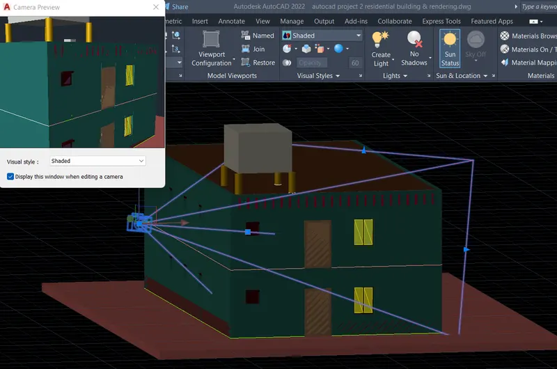
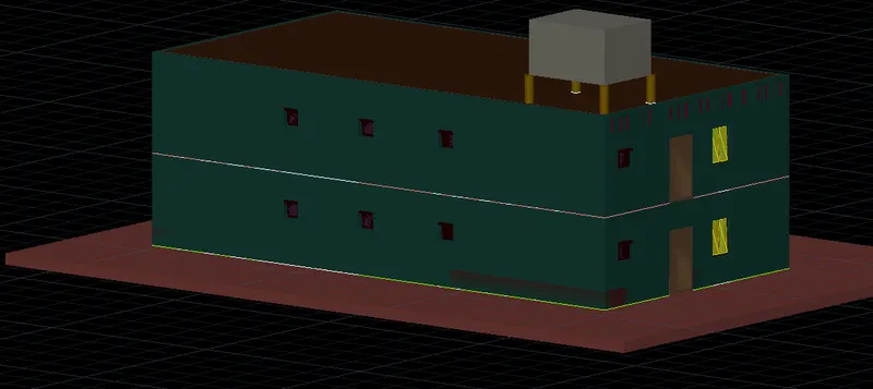
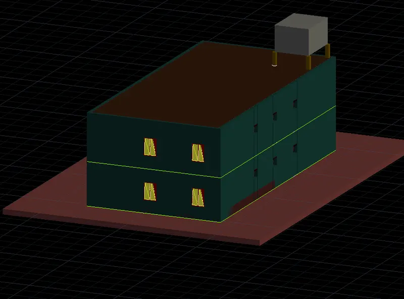
Residential building after assinging materials to the different components
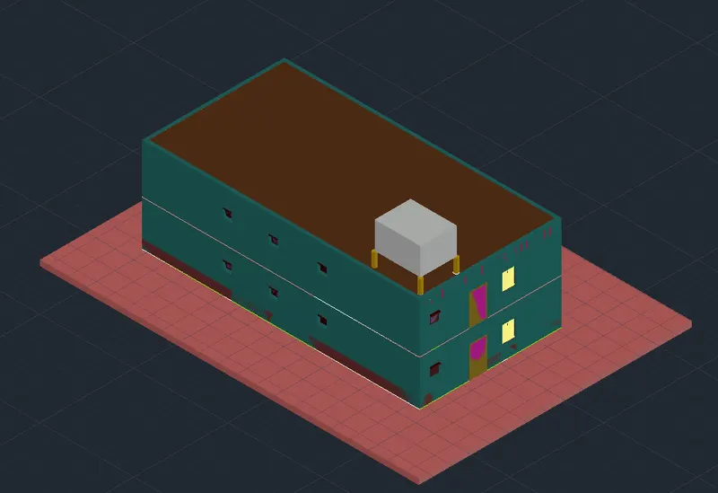
RESULTS:
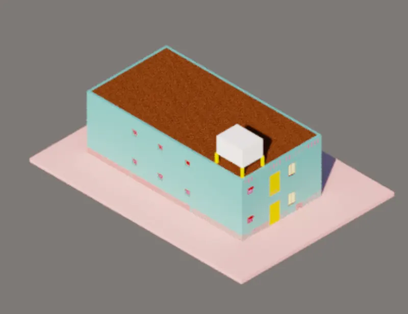
Residential building after rendering