Project 2_Creating a 3D rendered model for a Residential Building in AutoCad
1.Create a 3 dimensional model of the residential building with a rendered view.
Aim:
to draw the 3 dimensional model of a residential building with With rendered view.
Procedure:
Open Auto CAD and set the limits.Set the units to metric as the plot is in meters.
Commands used:
- Layer
- 3Dorbit
- Slice
- 3Drotate
- Extrude
- Material browser
- Region
- Boundary
- Line
- Offset
- Pline
- Trim
- Rectangle
Step 1:
Architectural drawing
a) Plan:
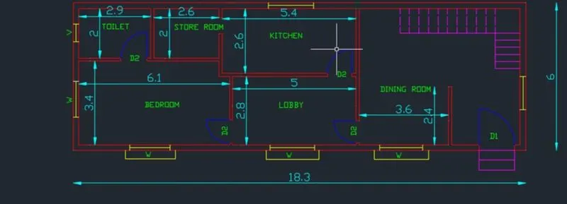
- Give the size of the plot using therectangle command and offset for the thickness of the wall.
- Give the orientation of the plot by marking the east direction.
- Now we draw the ground floor plan.
- Using offset command draw the bedroom of size 3.4X6.1m.
- Then for the toilet offset 2m in vertical direction and 2.9m in horizontal direction.
- For the store room offset 2m in vertical direction and 2.6m in horizontal direction.
- For the lobby offset 2.8m in vertical direction and 5m in horizontal direction.
- For kitchen offseth 2.6m in vertical direction and 5.4m in horizontal direction.
- Now draw the stairs from north of dining roomand 1m for the offset of the width of stair.
- Stair dimension thread-0.25m,riser 0.17m and and width-Im number of steps 16.
- Draw 5 steps in the first flight offseting 0.25m and draw a landing of 1m width.
- For the next 3nd flight steps again offset 0.25m and draw 11 steps.
- Now draw the dining room by offseting 3.6m in horizontal direction and 2.4m in vertical direction.
- Now insert the text using multiline text with text height as 0.10m style as standard.
- Now we draw the first floor plan:
- Copy the ground floor plan and we make few changes.
- The kitchen is replaced with bedroom with same size of the bedroom-2.6X5.4m and at bathroom is attached with it.
- In the North-east direction living. room is created of size 2.4mX2.8m by offseting in horizontal and vertical direction.
- Now we create the doors and windows and making them as block.
- Assume door sizes as: D1-1X2.1m and D2-0.90X2.1m
- Place the doors wherever opening is provided and mark them as D1 or D2 wherever required.
- Assume the size of windows as 1x1.7m and ventilator as 0.50X0.70m.
- Place the windows and ventilators in the required place.
- Mark them as W,V and make them in a block.
- Now insert the dimensions using "DIMLINEAR" command and for repeated dimensioning use "DIMCONTINUE" and give text height as 0.25.
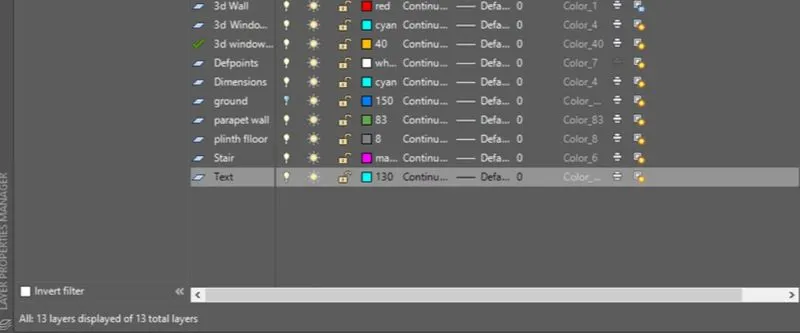
- Now create the layers using layer properties.
- Assign different colours to each layer in order to distinguish it.
- Insert respective elements in the layer.
- Insert steps in front of the entrance with riser as 0.15m and thread as 0.30m.
b) Elevation:
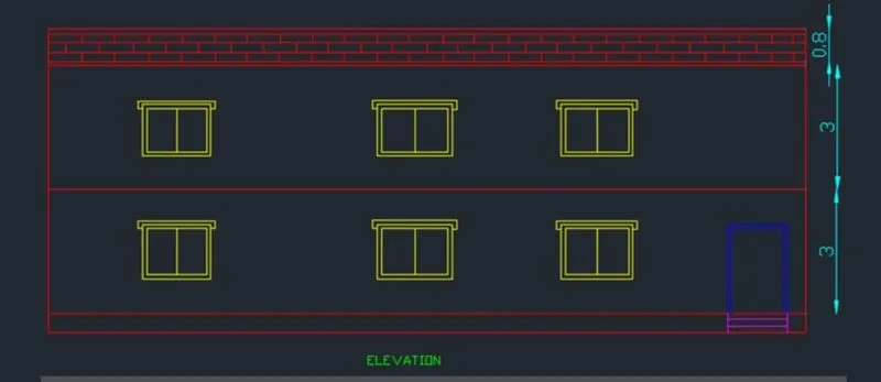
- Now project the lines to draw the elevation.
- Project the wall line to the top and draw an horizontal line,
- Offset 0.40m for the plinth level and 3m for the first floor level and 3m again for second floor.
- We draw the doors and windows from the plan and give height of 2m and Im as required.
- Project the shades and draw the shades at top of window level.
- Trim off the extra lines using trim command.
- Offset 0.076m for thickness of doors and windows
- Copy the windows and doors to other side also and draw the sunshade also.
- Project Im to top to show the parapet wall.
Layer properties:
Steps of constructing the 3d model:
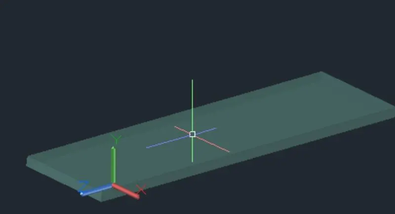
Create the plinth level by using Region and boundary.
- Create the wall by Extruding it.
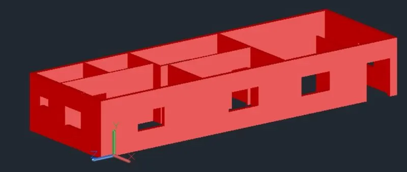
- Create the window and door and place it.
- Placing walls,door and windows together.
- Create the chajja.
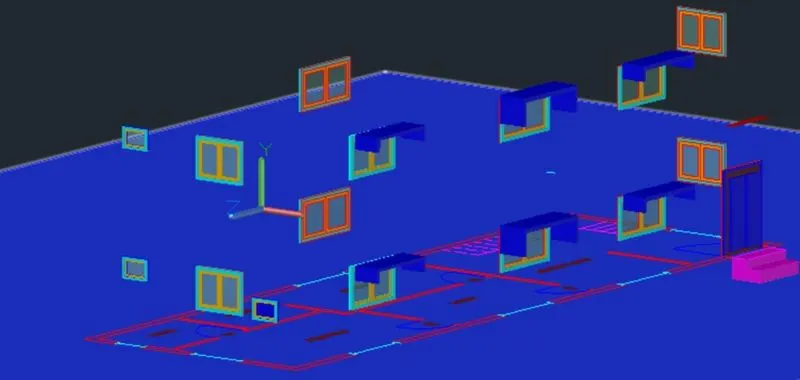
- Place the ceiling over the ground floor.
- Create the same as that is created in fround to the first floor.
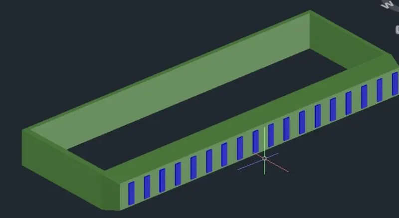
- Create the ceiling of the first floor and create the parapet wall.
- Create the stairs for the front door.
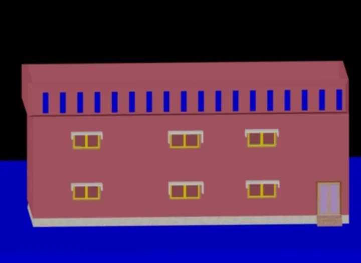
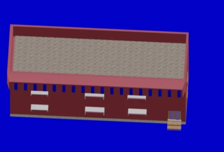
- Show the top and front view of the building.
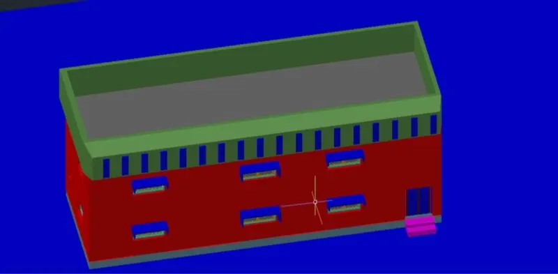
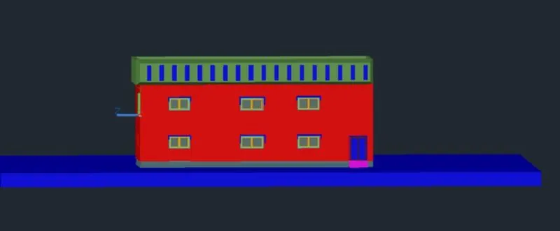
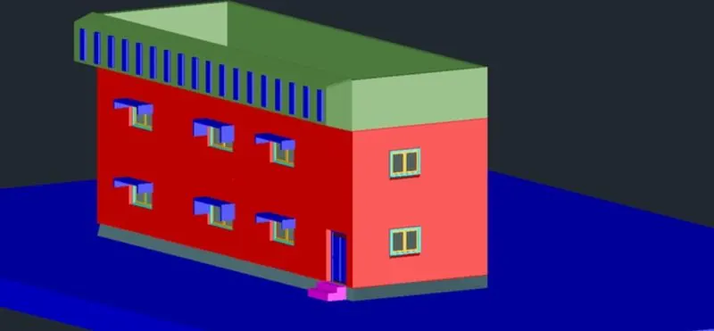
- Image after assinging the materials to the different components.
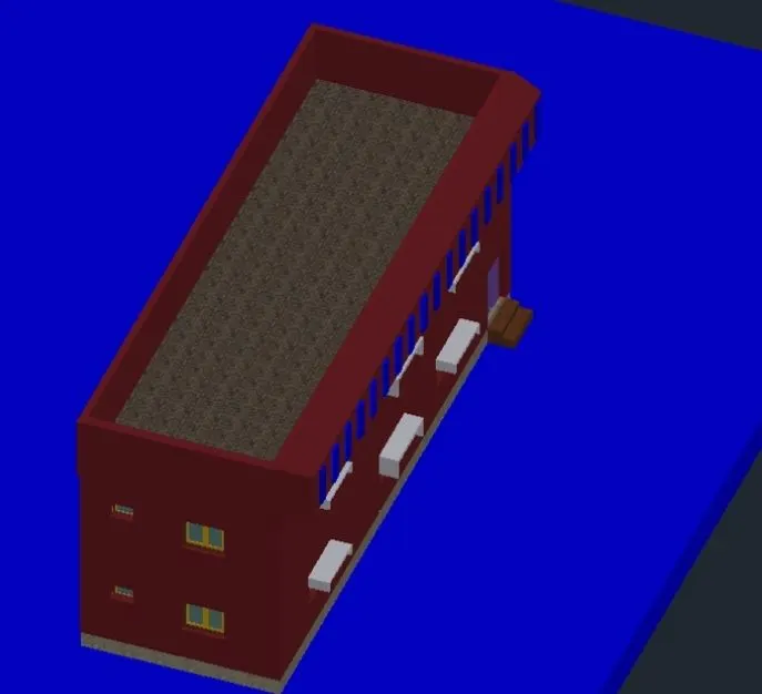
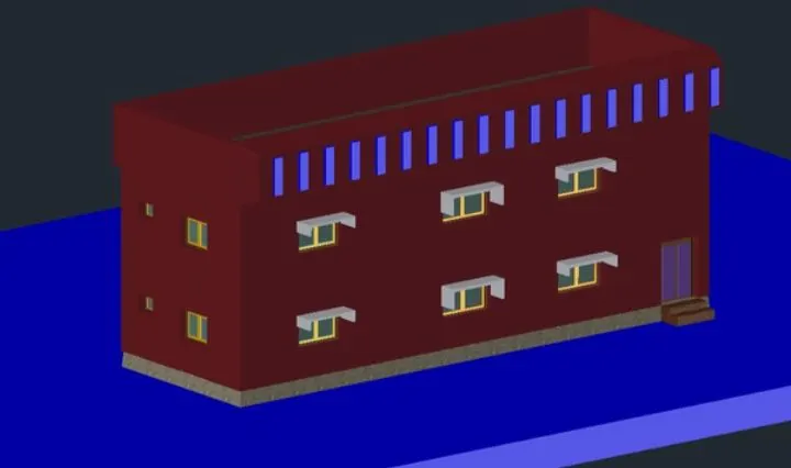
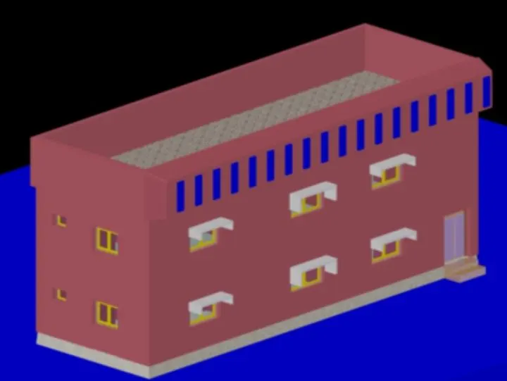
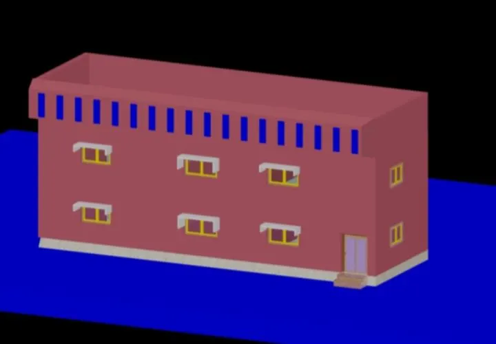
- At last the rendered image of the building.
Result: