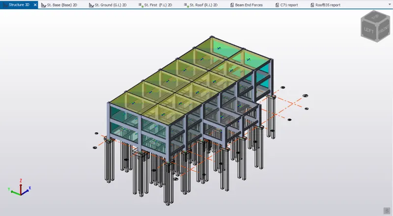
Project 2_Analyze and Design the RC office building as per IS standard code in TEKLA STRUCTURAL DESIGNER
Aim:
- To develop general arrangement for the RC office building.
- To analyze and design the building as per IS standard code in TEKLA STRUCTURAL DESIGNER and the building to be designed for dead, live, wind and seismic loading.
- To generate report of each member and to extract drawings for structural plans, beam reinforcement details from the software.
Introduction:
- Tekla Structural Designer is a software that allows you to design reinforced concrete buildings and steel buildings.
- In this project, Using TEKLA structural designer a RC office building is modelled, analyzed and designed as per IS Standard code.
Procedure:
- Open a new TSD FILE.
- Save the new file as Project 2. RC office building.
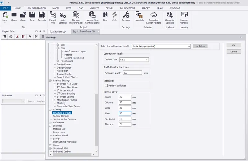
- Go to home -> settings and do the following checks.
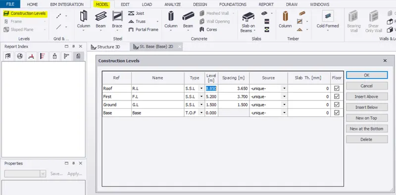
- Go to model -> construction levels and enter the level heights as shown below.
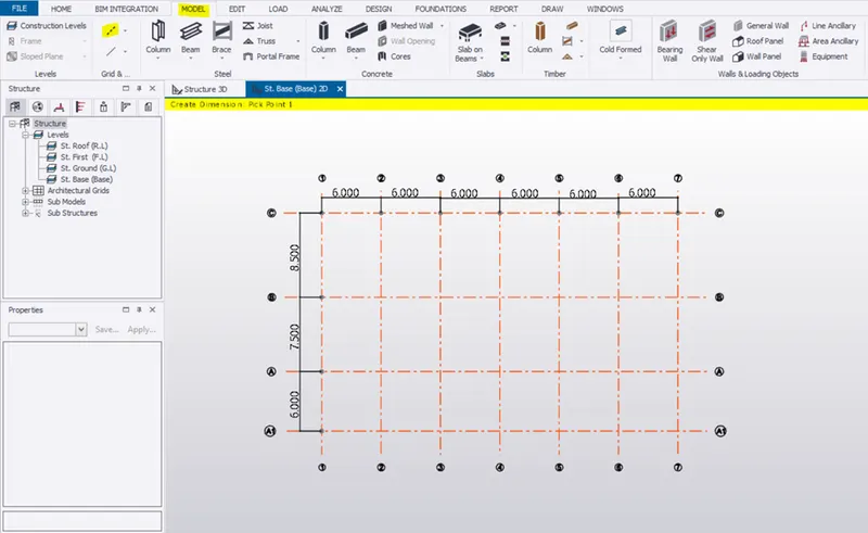
- Go to model -> grid lines and take parallel quick option to keep making vertical and horizontal grid lines.
- Modeling:
- Column:
- Go to home -> manage property sets -> new -> member- > concrete column and create property for column.
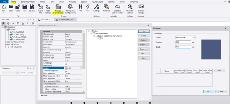
- Go to B.L and select concrete column and select the grid intersections by having the C1 property.
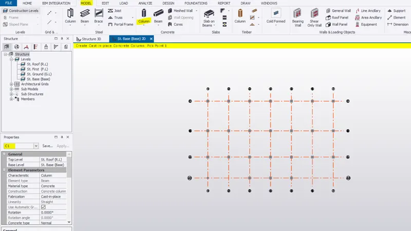
- Beam:
- Go to home -> manage property sets -> new -> member- > concrete beam and create property for Primary beam.
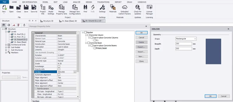
- Go to Home -> Manage property set-> new -> member -> concrete beam and select the property for secondary beam.
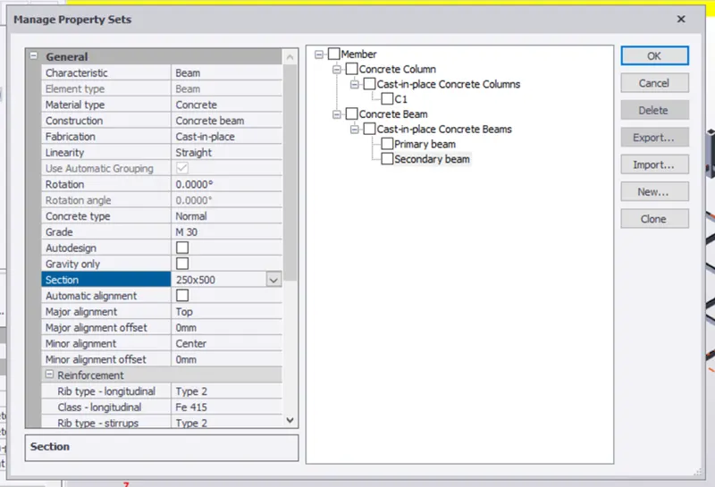
- Go to G.L , select Primary beam in property window and create beam.
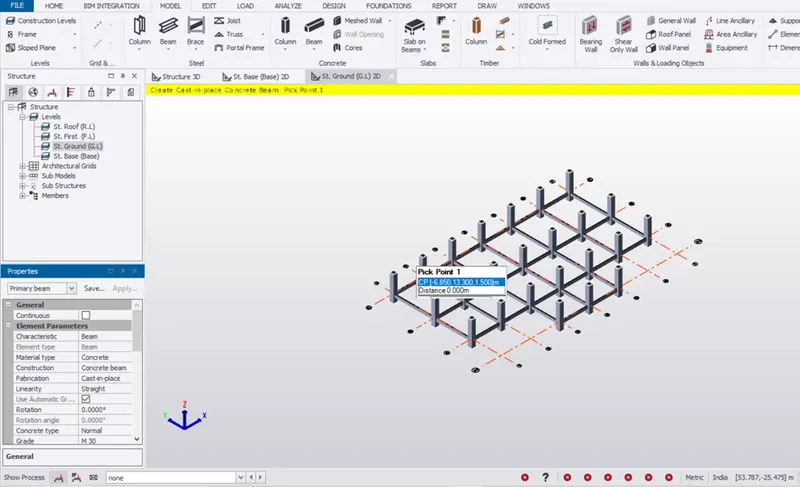
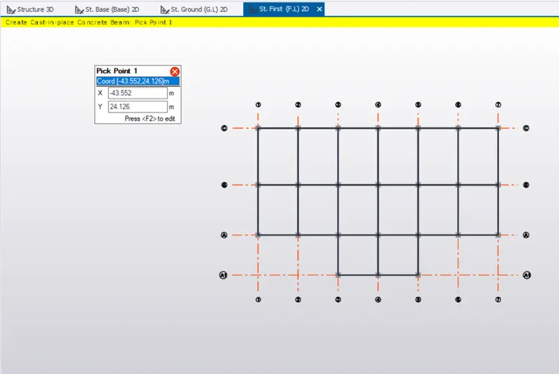
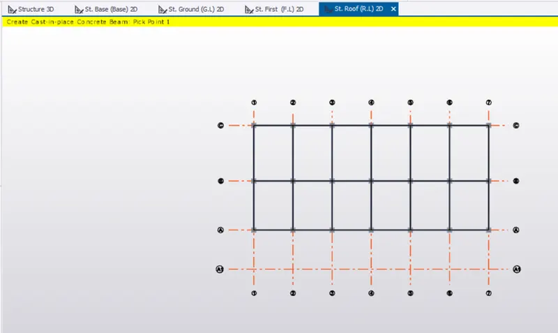
- Go to above floor and do the same,
- First floor level:
- Roof level:
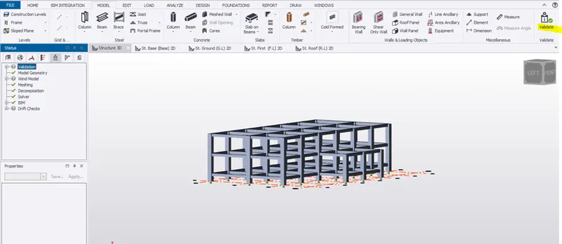
- Validation:
- Click validate to validate the
- Create construction lines in the ground floor for modeling secondary beams.
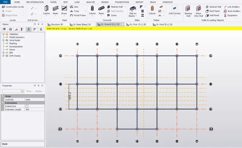
- Go to model -> concrete beam -> select secondary beam and create secondary beam according to the plan as shown below.
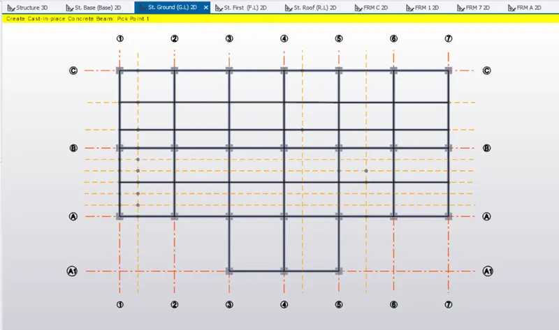
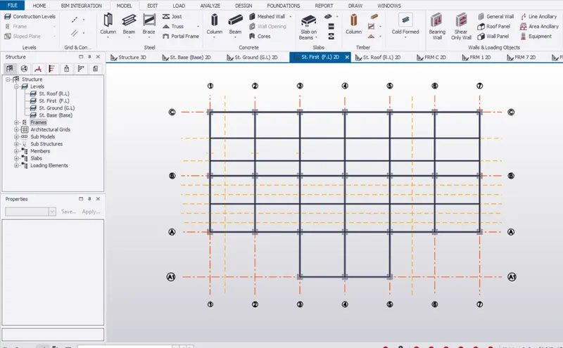
- Repeat the same process in first floor.
- Slab:
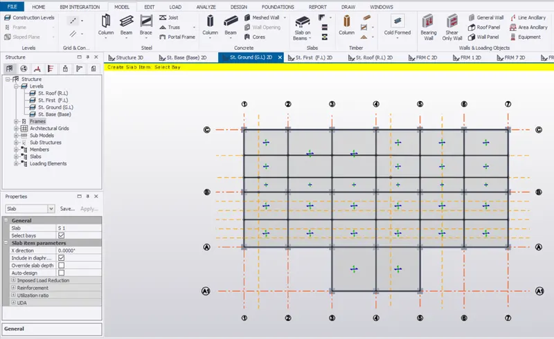
- Go to home -> manage property type-> new -> slab -> general slab item.
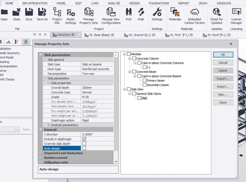
- Go to G.L, model the slab by slab on beam icon
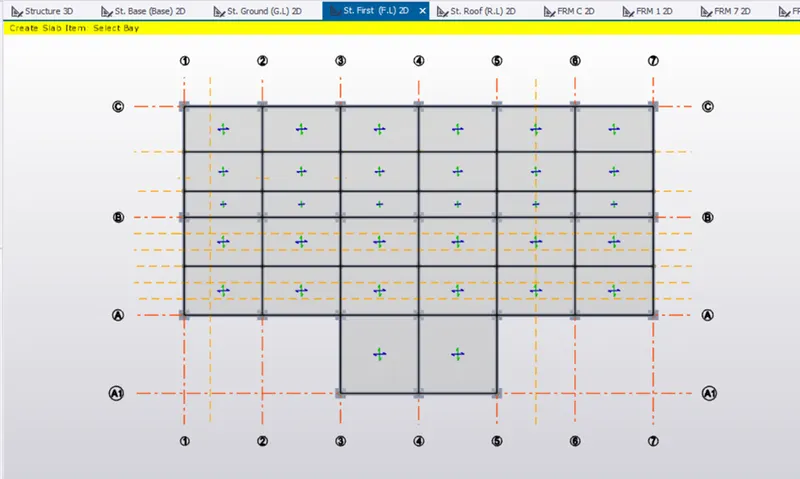
- Follow the same in F.L.
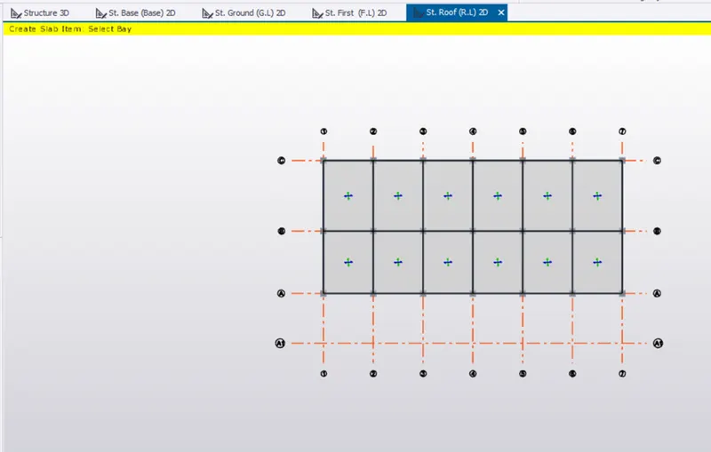
- Roof level:
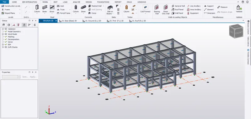
- Validate the model
- Frame creation:
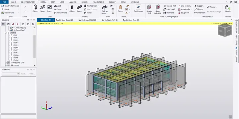
- Go to 3D and click frames and select all the grid lines to create frames
- Wall panel:
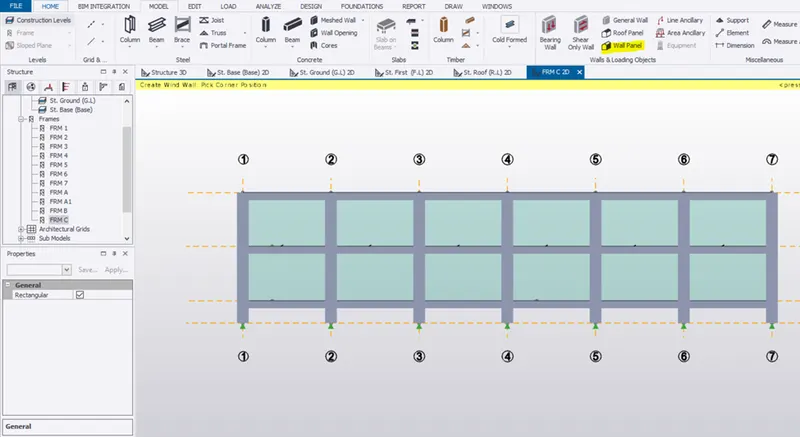
- Go to FRM C 2D and create wind panels by clicking wind panel icon and pick the opposite corners connecting columns.
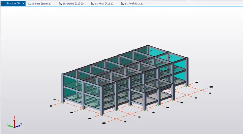
- Similarly do on all 4 sides of the building
- Roof panel:
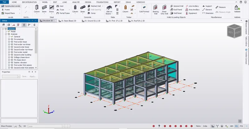
- Go to 3D Structures and select roof panel icon and pick 5 corner points.
- Dead load calculation:
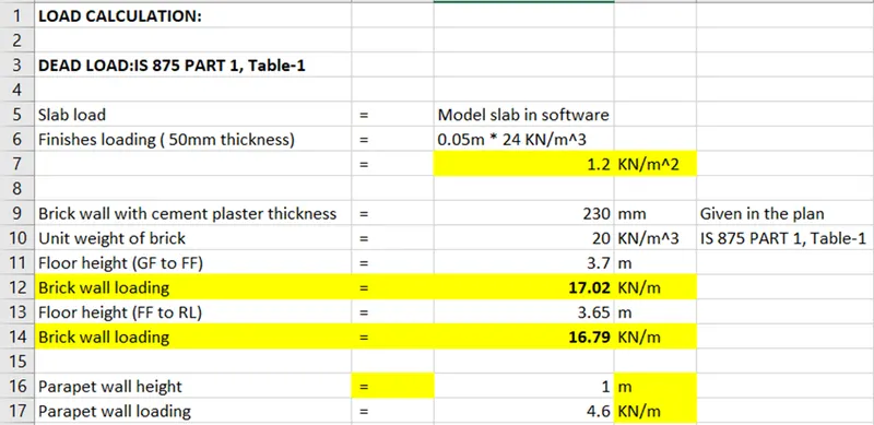
- Open EXCEL to do the calculation.
- Enter the value as shown below.
- Applying finishes:
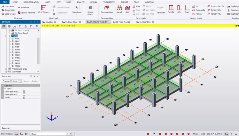
- Go to G.L and select the dead load from the drop down below and select load -> Area load
- Give the value and loading as shown below.
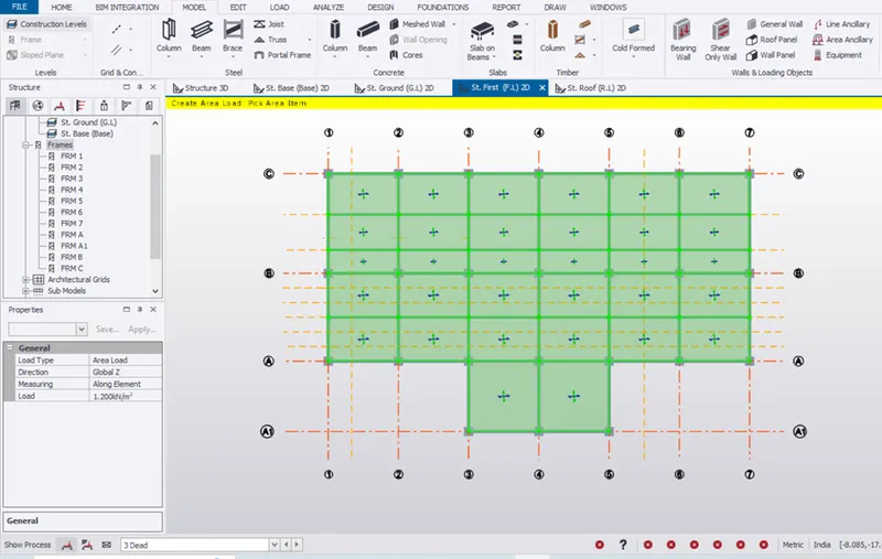
- Go to F.L and follow the same procedure.
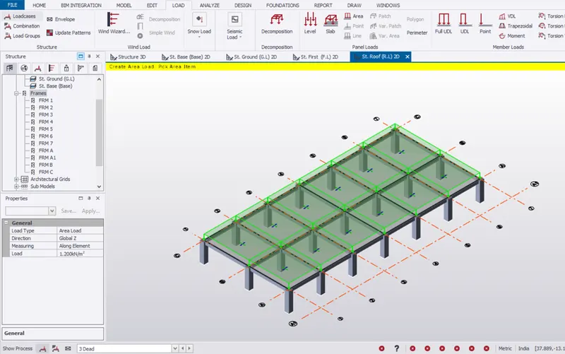
- On roof level
- Applying member load:
- Go to G.L and select load -> Full UDL
- Enter the value of load in the property window and click the member as shown below.
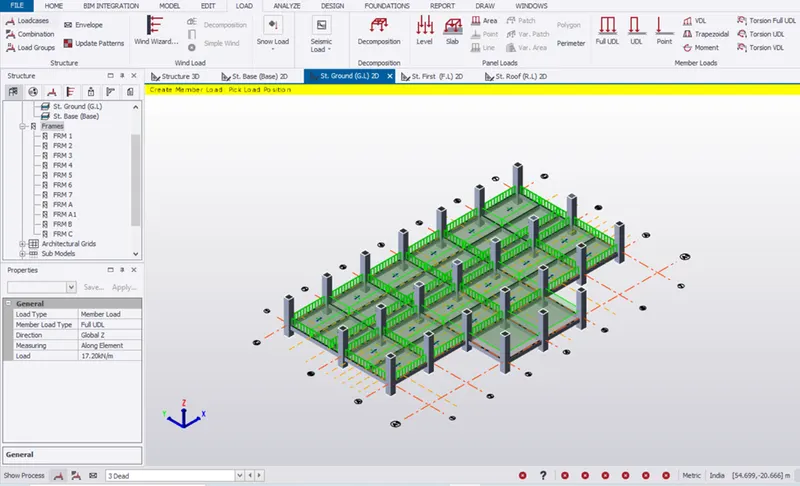
- Follow the same procedure on first floor.
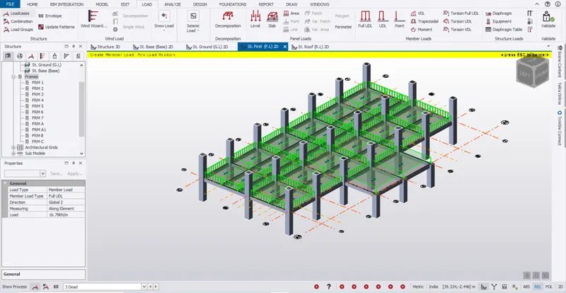
- On roof level
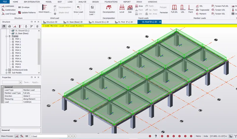
- Applying member load,
- Go to G.L and select line and create by picking reference pont.
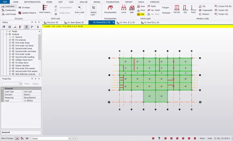
- On F.L,
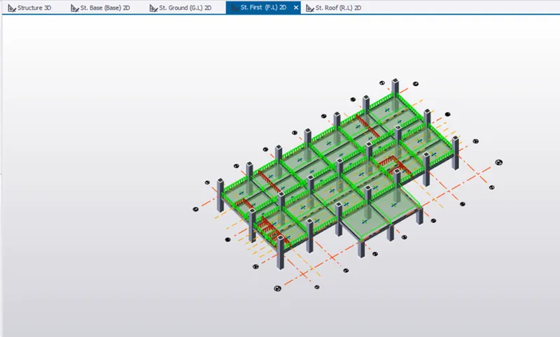
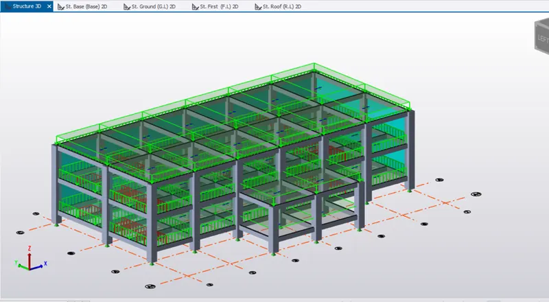
- 3D View,
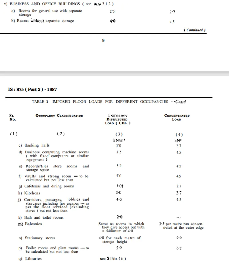
- Live load calculation:
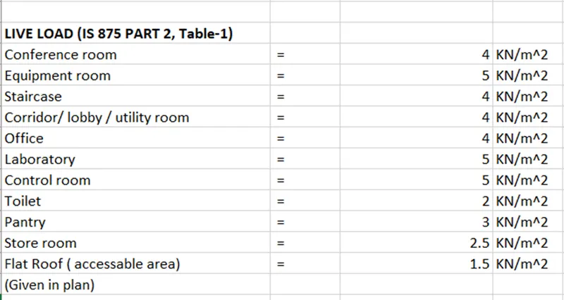
- Refer IS 875 Part -2, Table- 1 for Live load
- For roof,
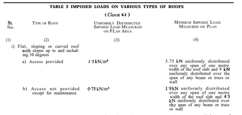
- Open EXCEL and enter the values.
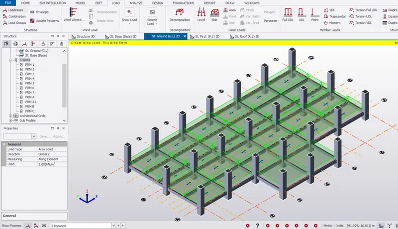
- Go to G.F and select load-> area load and give loading as per the calculation
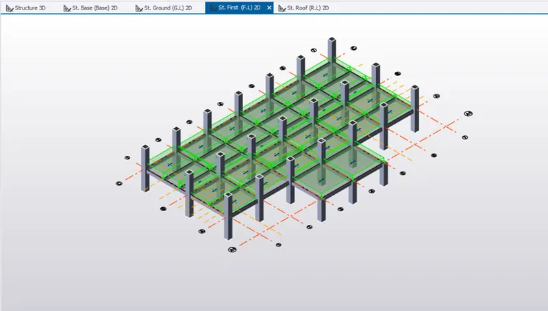
- Go to F.L and select load-> area load and give loading as per the calculation
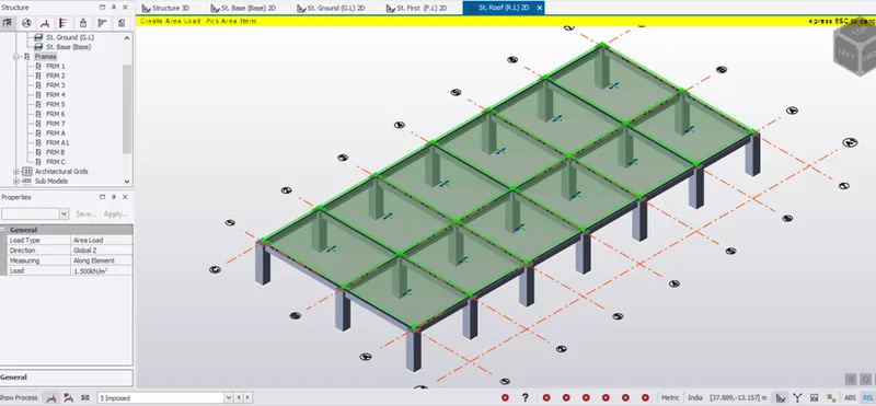
- On roof
- Wind load calculation:
- Open Excel sheet for calculation and open TSD file which created early to check dimension of the building.
- Refer code IS 875 Part-3 2015 for,
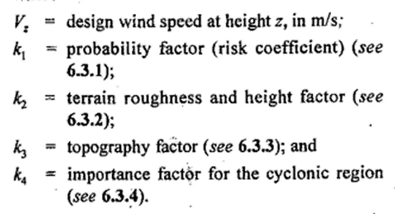
- For K1,
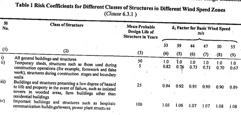
- K2 factor is,
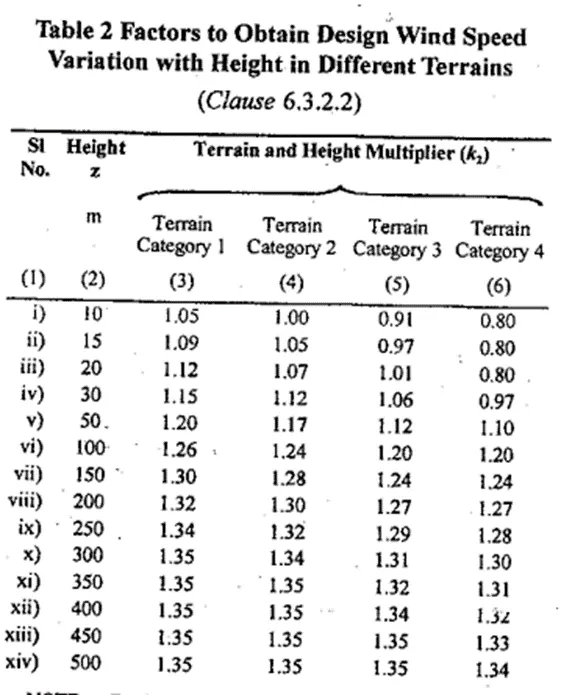
- For k3,
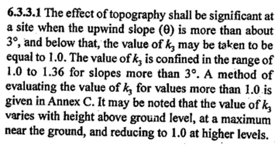
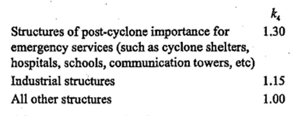
- For k4,
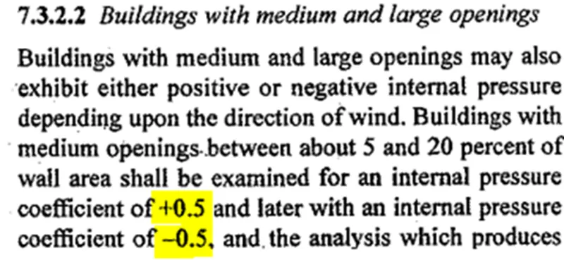
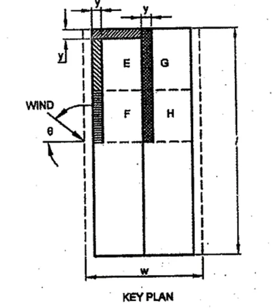
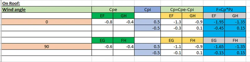
- Internal pressure coefficient- 7.3.2.2
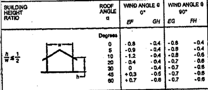
- For external co-efficient, Refer Table 5

- With the above reference, Enter the value in excel for calculation.
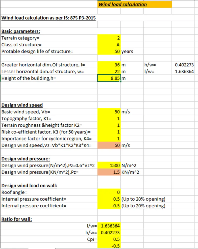

- On roof,
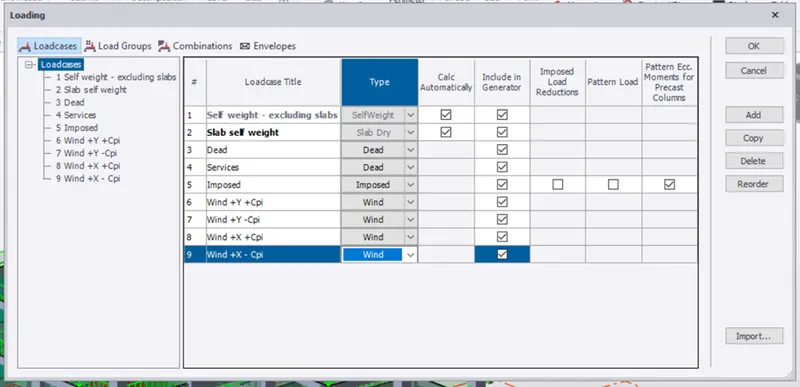
- Creating load case:
- Go to load -> Load cases-> add
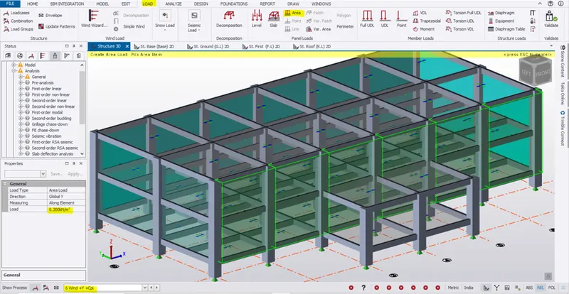
- Applying wind load: Wind +Y +Cpi
- Select the load case -> load -> area load and enter the loading on the property window by referring the wind load calculation and select the wall panel on wind ward side, which is face A.
- On face B,
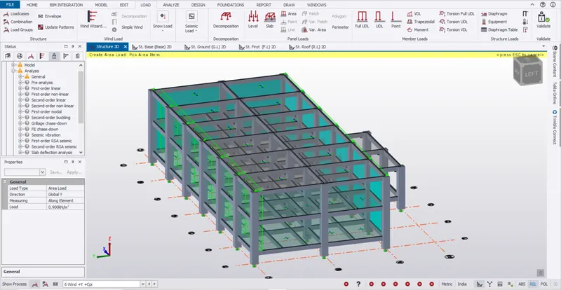
- Follow the same procedure on wee ward side, which are face C and D.
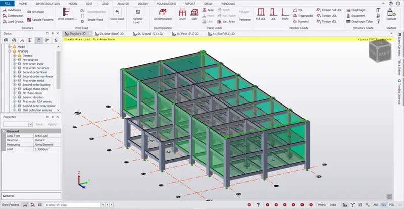
- On roof,
- Follow the same procedure to apply load on other load case and referring the wind load calculation.
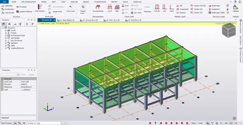
- For Wind +Y -Cpi,
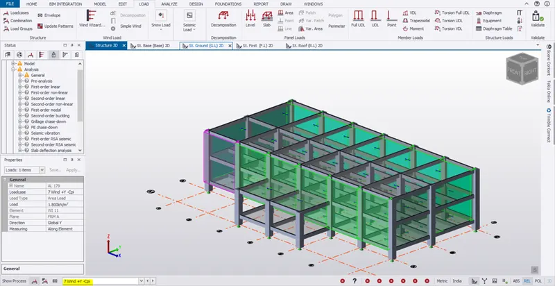
- On roof,
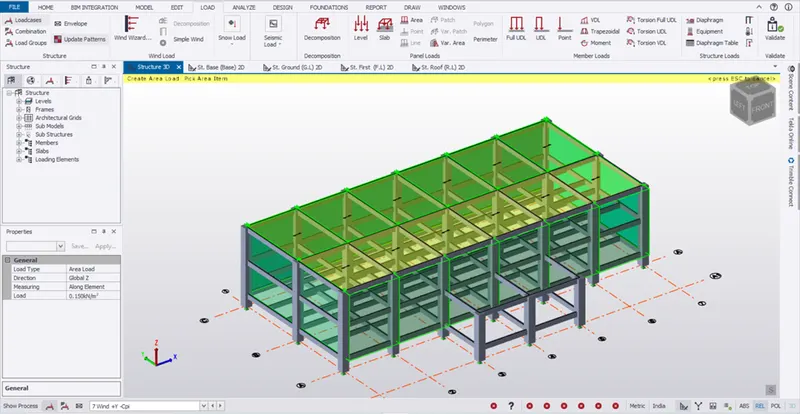
- For +X +Cpi, change the global direction as global X.
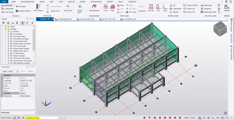
- On roof,
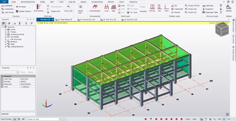
- For +X -Cpi,
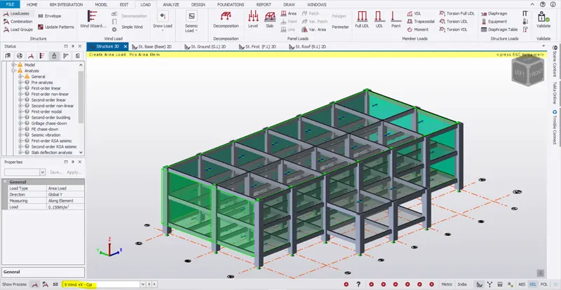
- On roof,
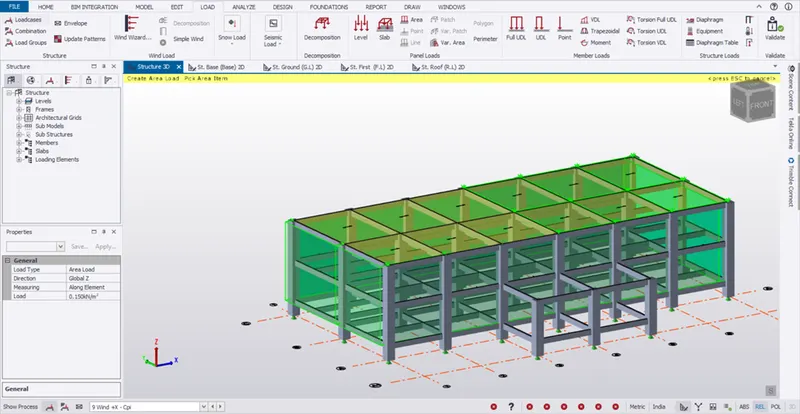
- Seismic loading:
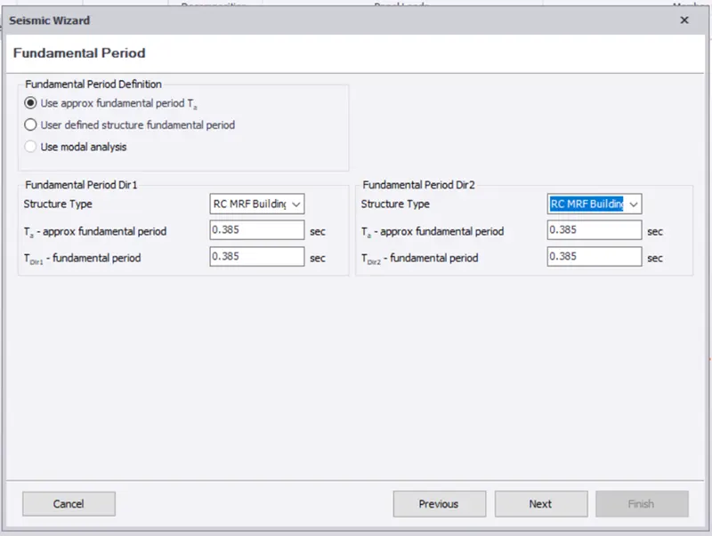
- Go to load -> seismic load -> seismic wizard
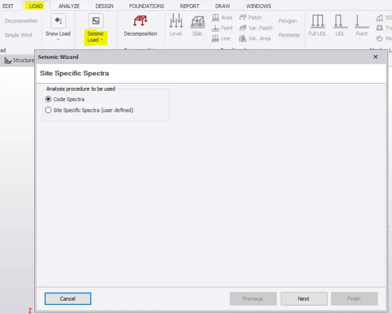
- Click next.
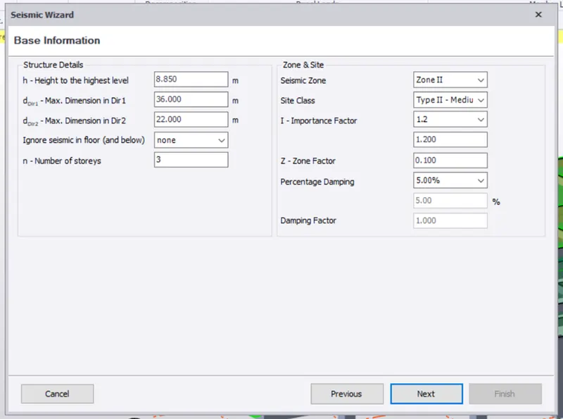
- Above mentioned values are to be checked as per the code.
- Refer IS 1893 ( PART 1)- 2002
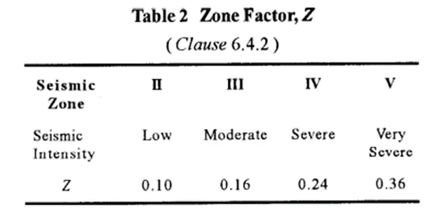
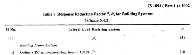
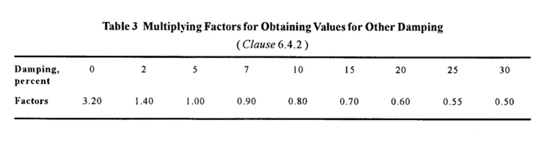
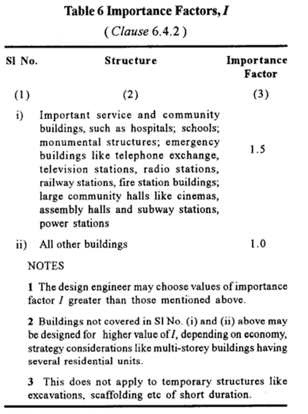
- Click next once the checks are done.
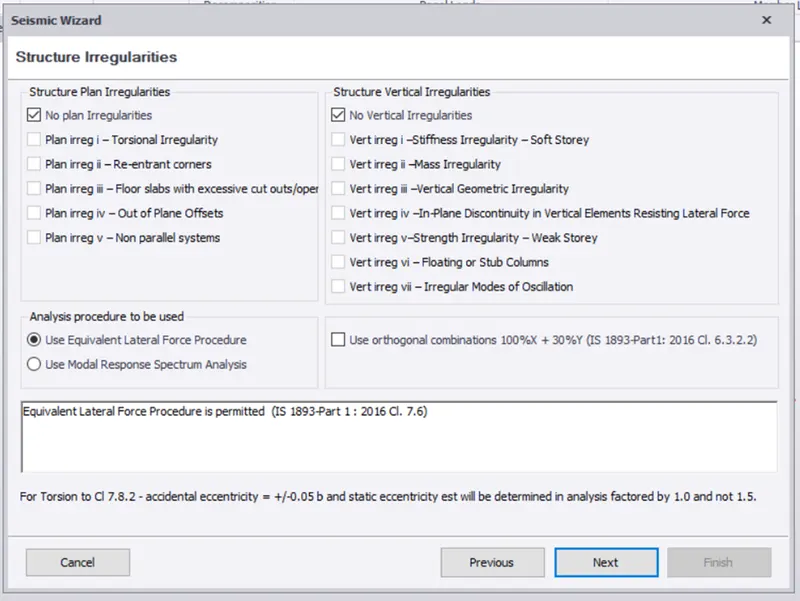
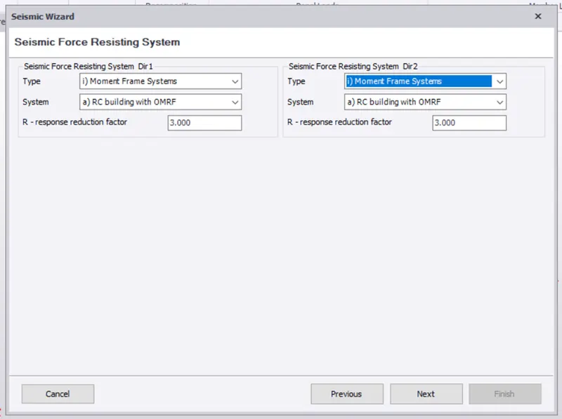
- Select the seismic resisting frame type as shown below.
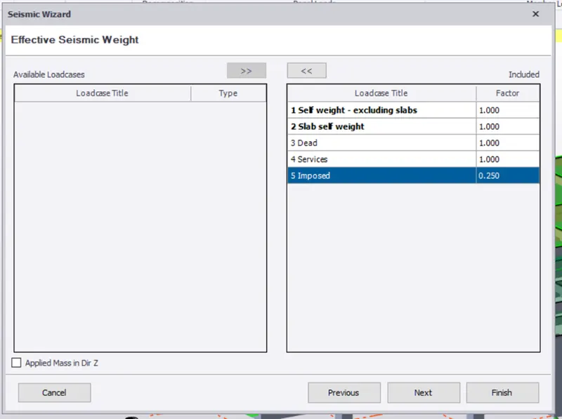
- Click finish
- Click finish
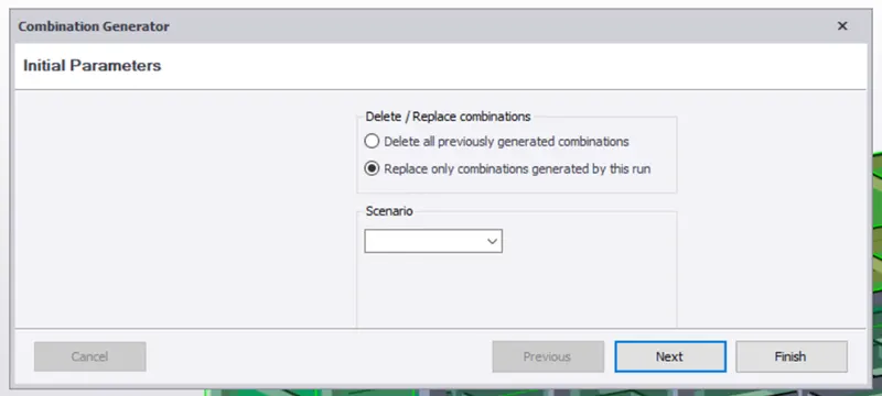
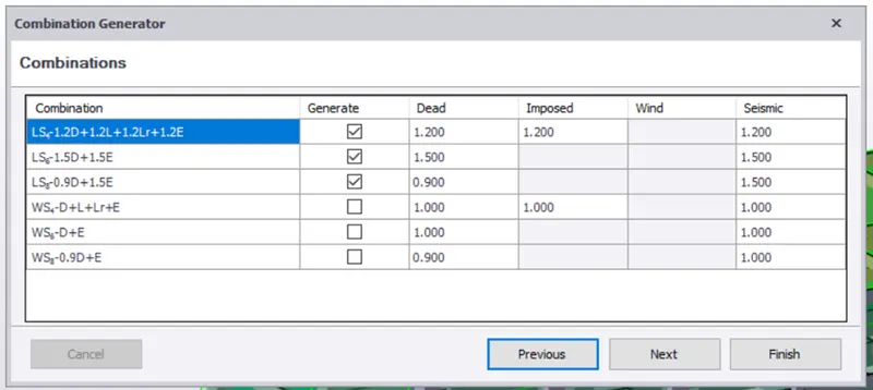
- Go to load -> load combination -> Generate.
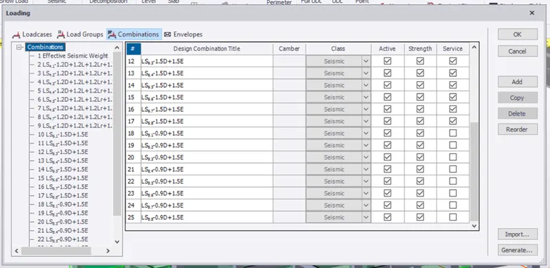
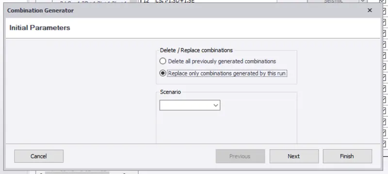
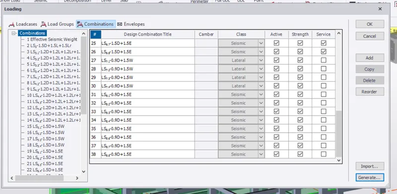
- The load is generated.
- Run analysis:
- After assigning all the loads, go to analyze -> 1st order linear
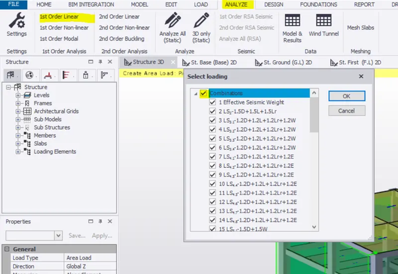
- Click ok and go to result view to check to results.
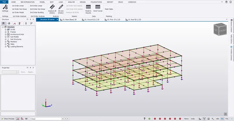
- Deflection:
- Go to result view -> deflection to see the deflection in all load case and combination by selecting it in the drop down below.
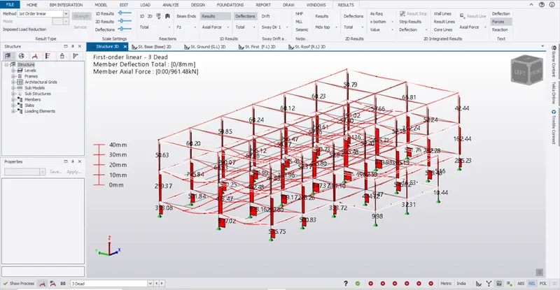
- Axial force:
- Go to any frame and check it for axial force in tge panel drop down as shown below
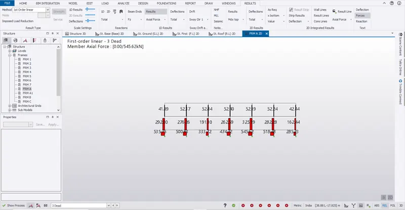
- Frame view:
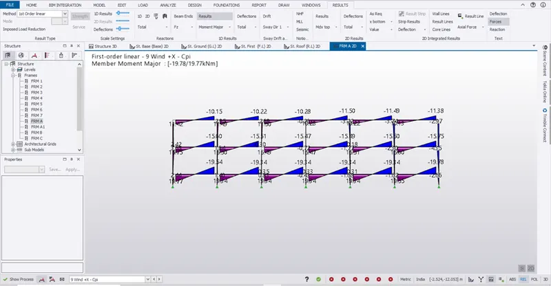
- Similarly for Moment major,
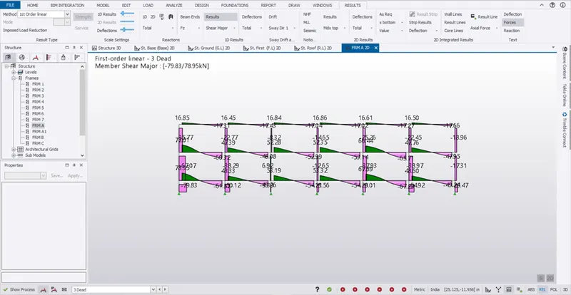
- Shear major,
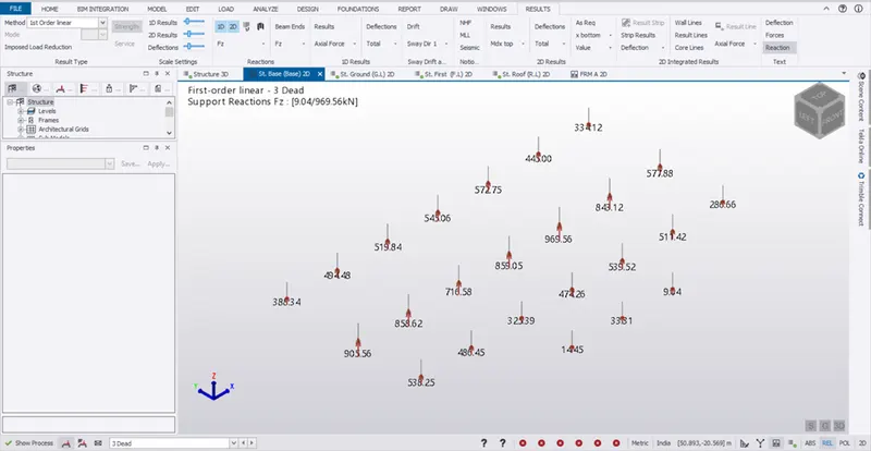
- Reactions:
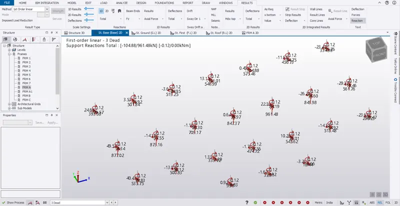
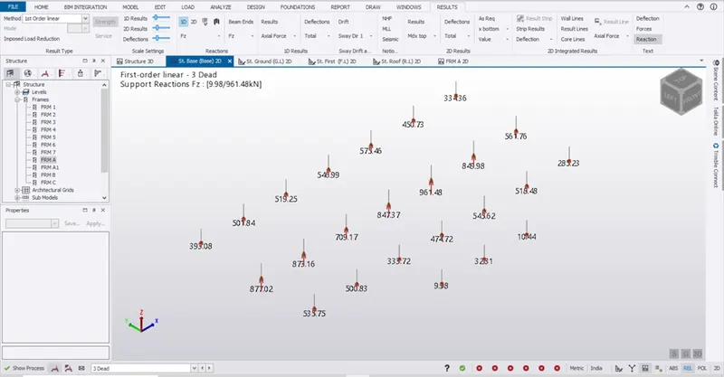
- Go to Base level and click reaction in panel to see the reactions,
- Designing the members:
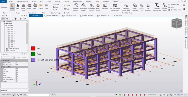
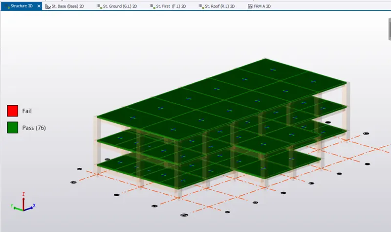
- Go to review view to view the status of the members
- Column:
- Go to 3D Structure and check a column and reinforcement
- Select a column -> right click ->interactive design -> Static.
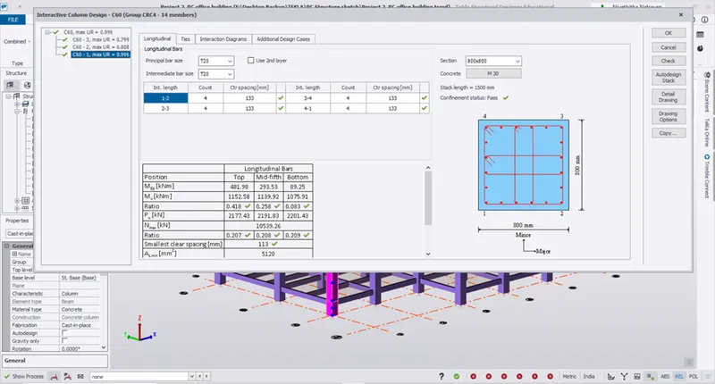
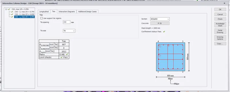
- Similarly check all other columns for its reinforcement details like main bar and ties.
- If it fails increase the reinforcement and section of the column
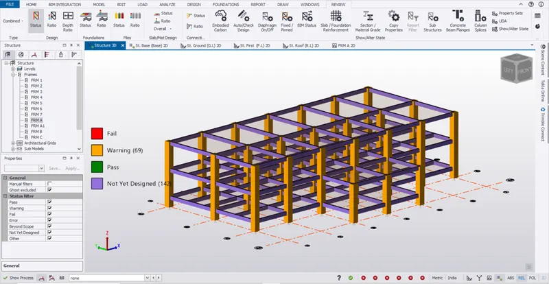
- All the columns are passed.
- Beam:
- Go to F.L and uncheck all the members other than beam in scene content.
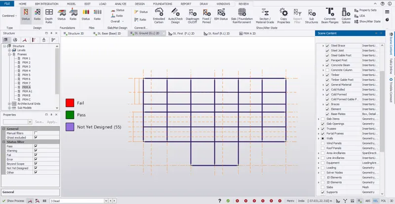
- Select a beam -> right click -> interactive design ->static
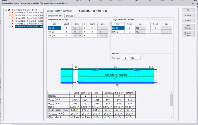
- Find the problem by clicking check button
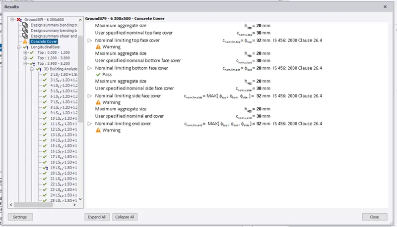
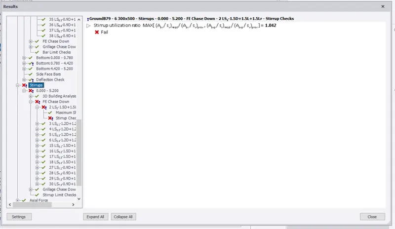
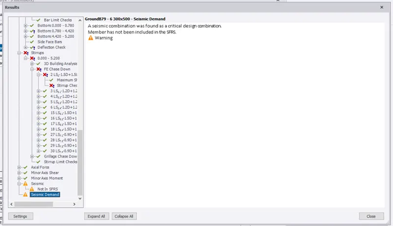
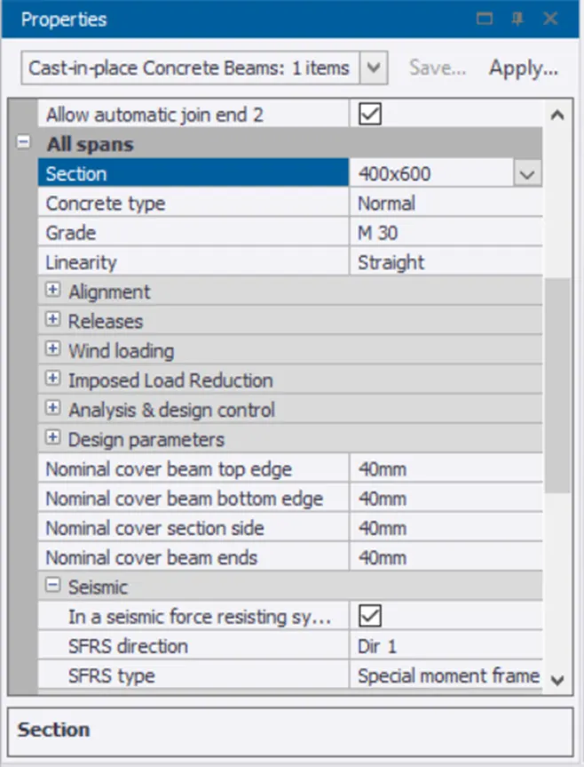
- Change the section of the beam
- Change the reinforcement details for longitudinal and main bar as shown below.
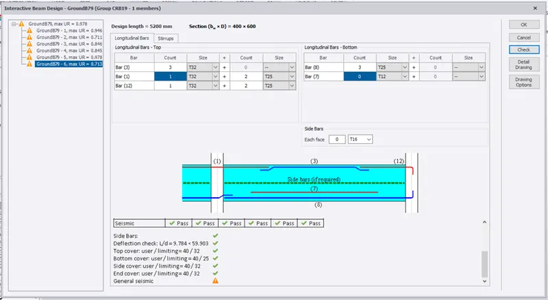
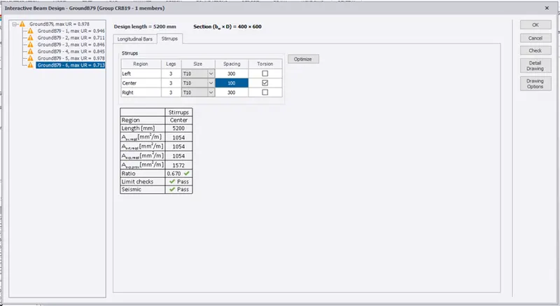
- Beam is passed with a warning.
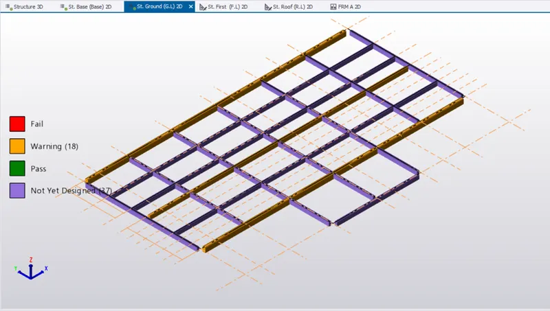
- Secondary beams are passed after changing the cover to 40mm
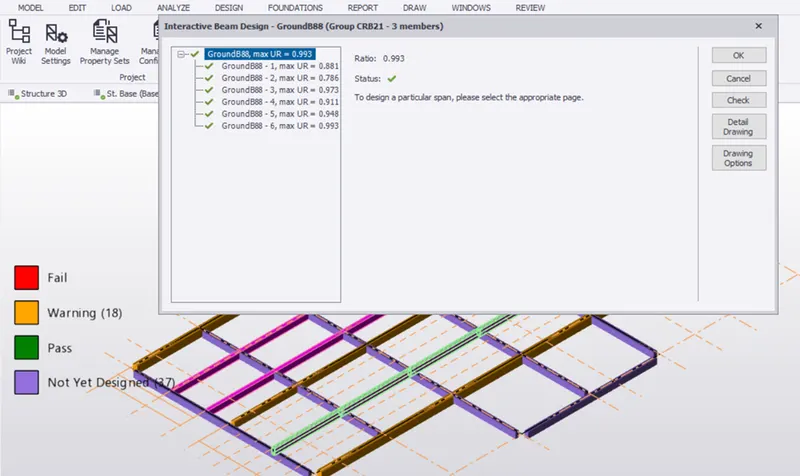
- Similarly check the properties of the other beams.
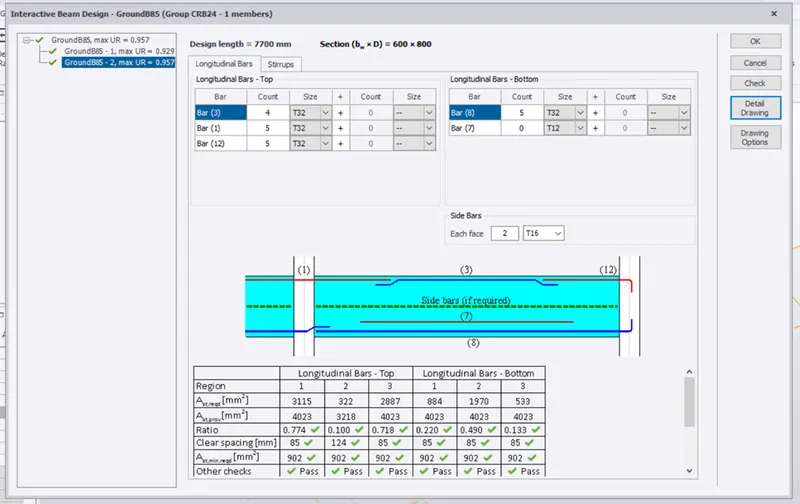
- Click detail drawing to view the drawing in AUTOCAD
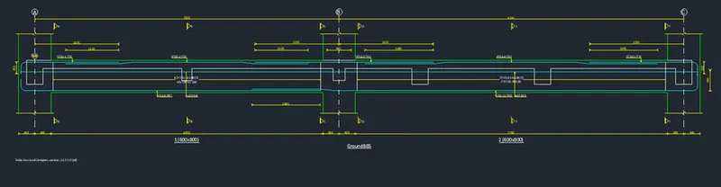
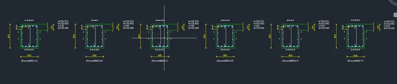
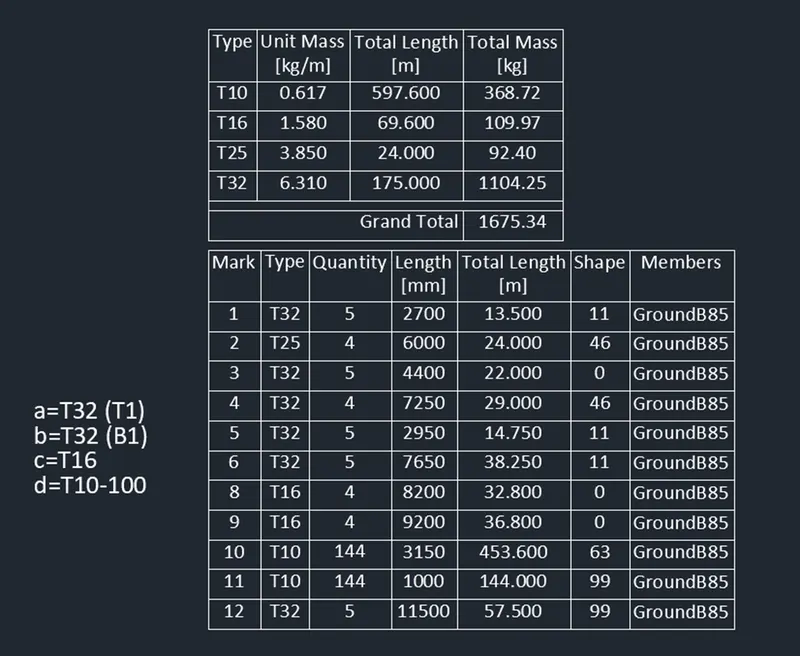
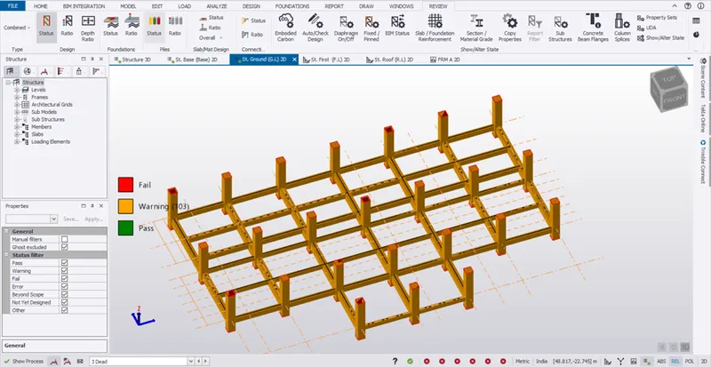
- All the members in the ground level are passed
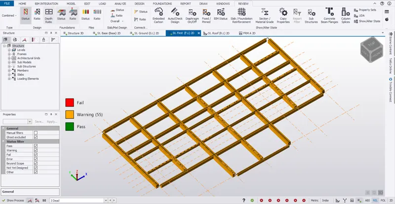
- Similarly go to F.L and check the beams and change the reinforcement and section as required
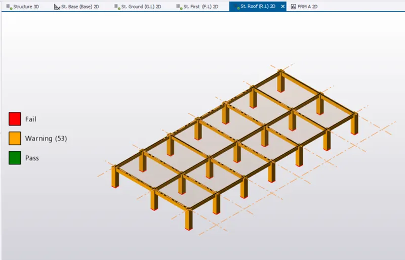
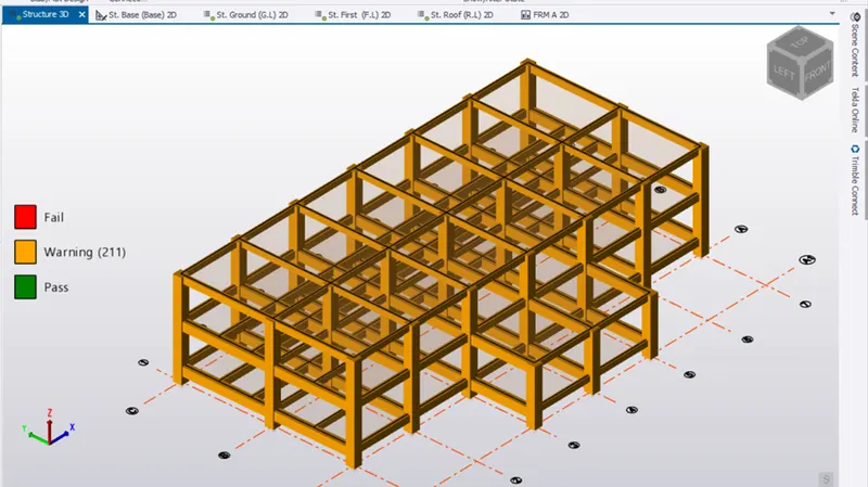
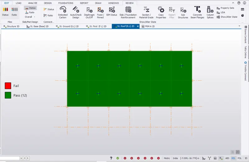
- Slab:
- Go to G.L and select a slab-> right click -> check panel
- check if it passes or fail
- If fails change the reinforcement and do the check again
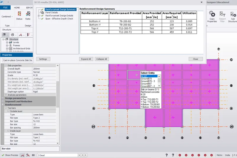
- All slabs are passed
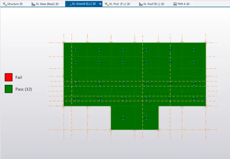
- Go to F.L and follow the same procedure.
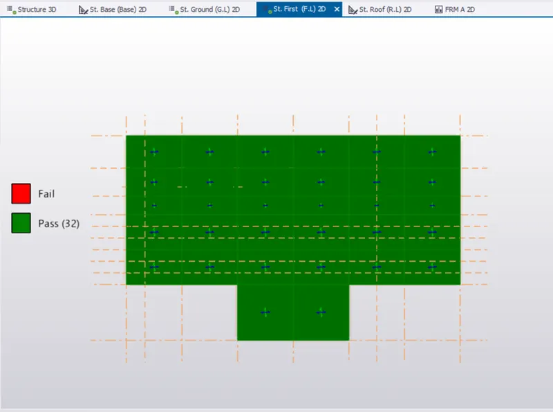
- Similarly for R.L
- Foundation design:
- Go to base level and check the reaction
- Go to foundation tab -> catalog-> add
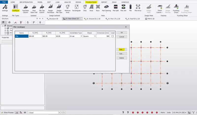
- Click ok
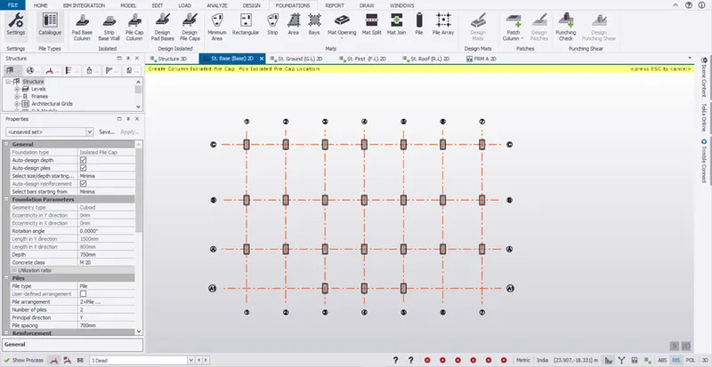
- Click pile cap column and select all columns as a whole.
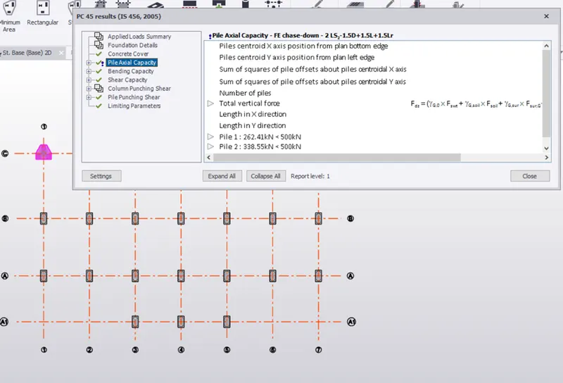
- Select a pile cap à right click à design member
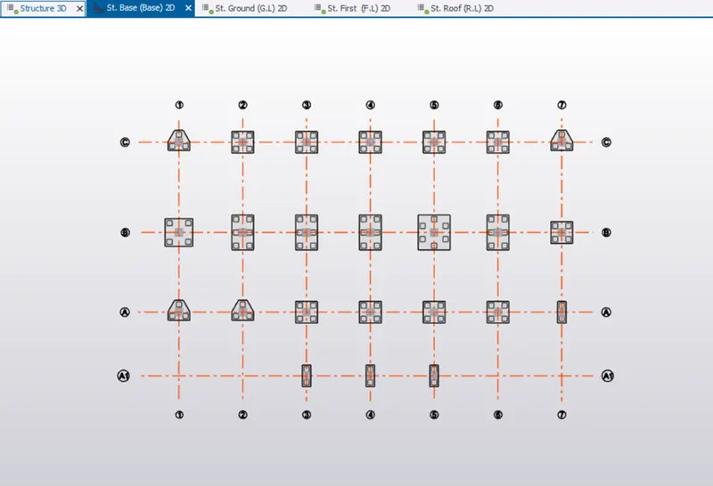
- Similarly do for all other columns
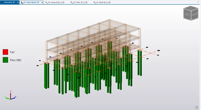
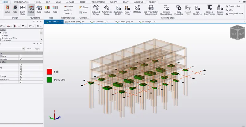
- 3D View of the structure:
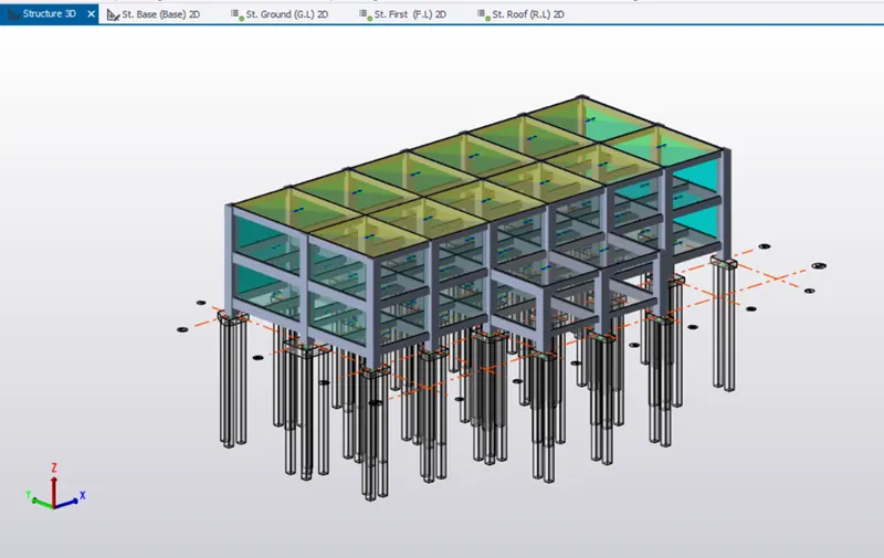
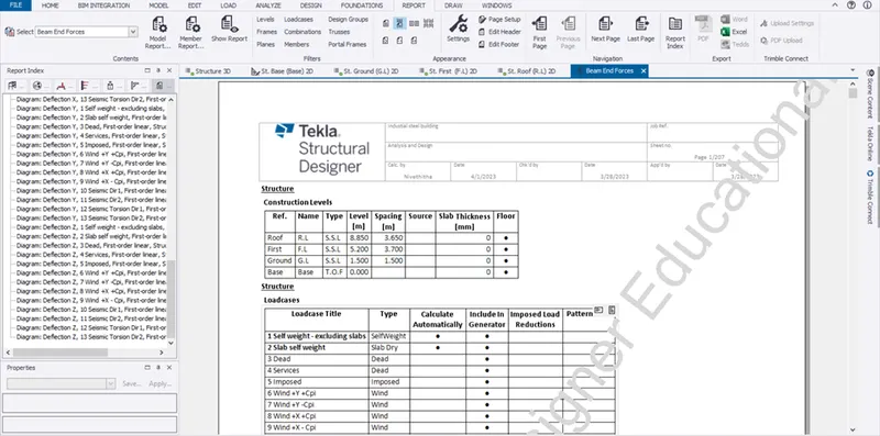
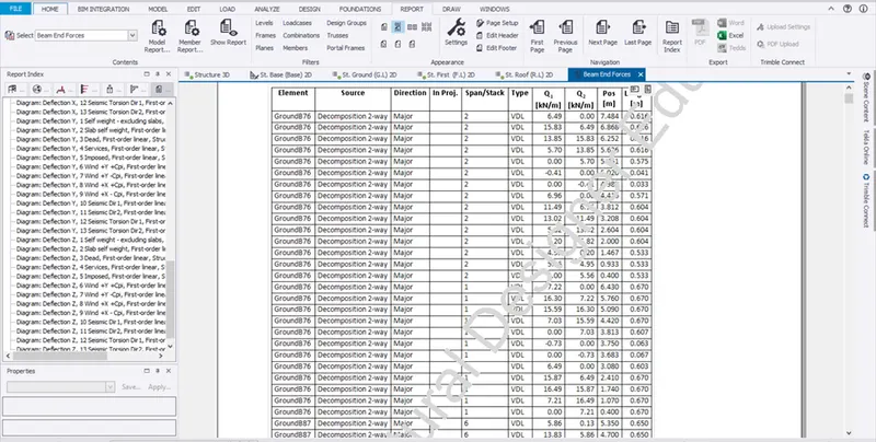
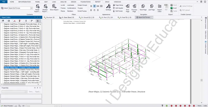
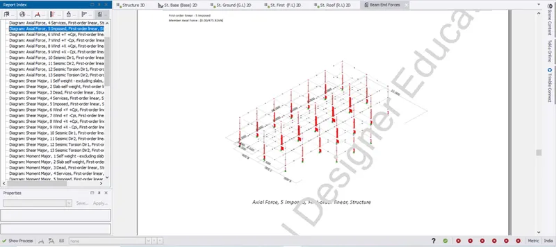
- Model report:
- Go to report-> Select Beam end forces ->Model report setting
- In that select the following options which the reports to be displayed by click and dragging.
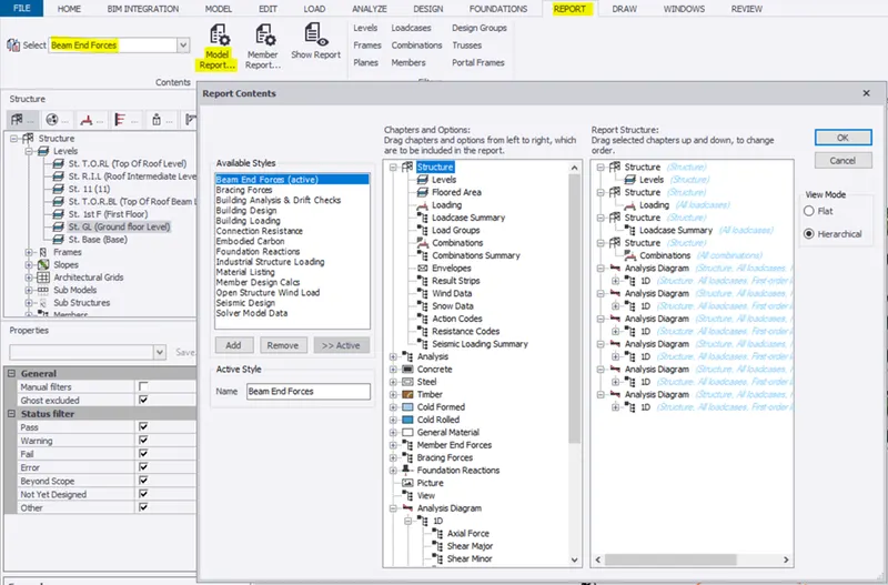
- Now click show report to display the report.
- Member report:
- Go to Report -> Member report settings to create a format for the report for a particular member like beam , column, etc,.
- For instance, take concrete beam
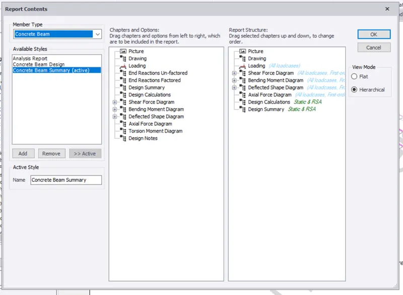
- Click ok
- Now go to 3D Structure and right click on any beam- > report for member
- Click show report
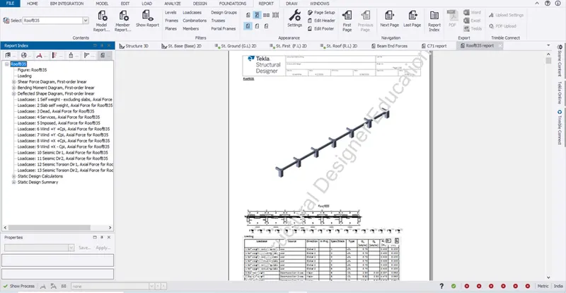
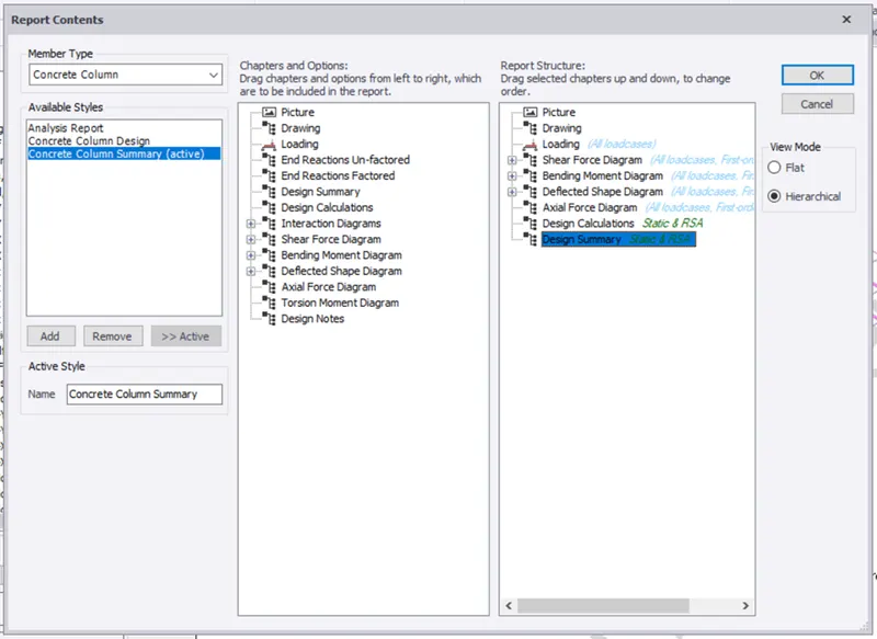
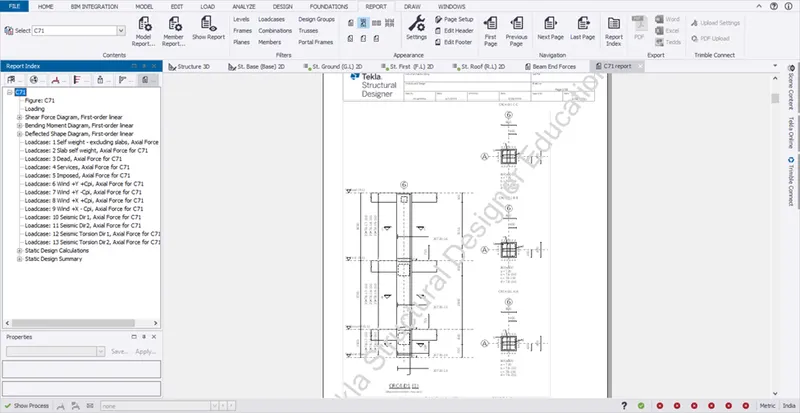
- Follow the same procedure for column.
- For concrete column,
- Generating plan:
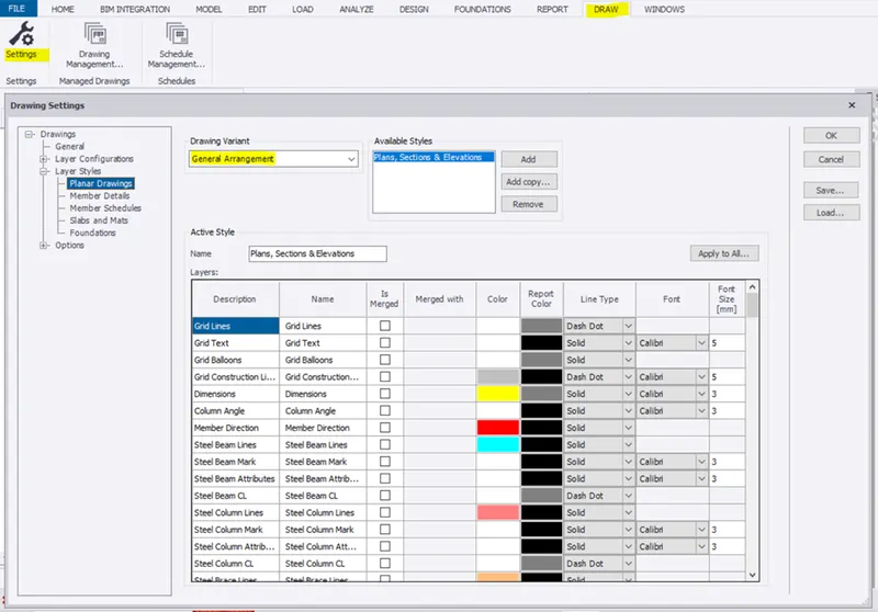
- Go to Draw -> settings and check the following options.
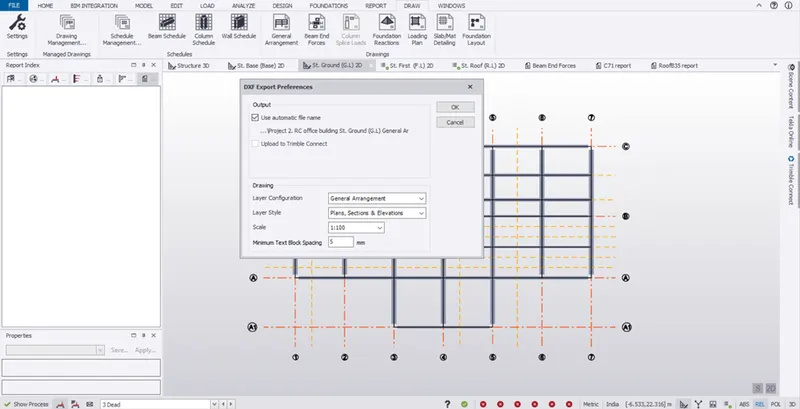
- Go to G.L in level-> Select Draw -> General arrangement and click ok
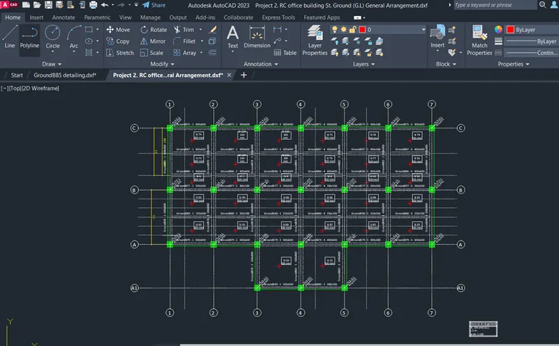
- Similarly other level floor plan can be obtained by this method.
- Result:
- Hence the RC office building is model, analyzed, designed in Tekla structural designer with reports of details and floor plans.