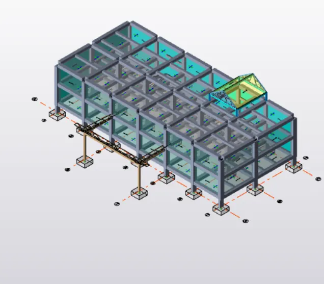
Project 2_Analyze and Design the RC office building as per IS standard code in TEKLA STRUCTURAL DESIGNER
AIM : To Analyze and design RC office building as per IS standard code in TEKLA STRUCTURAL DESIGNER.
INTRODUCTION : Tekla software is a building information modeling software tool to model all types of structures. It allows 3D modeling, 2D drawing and access building information. Tekla structure, basic building objects are provided and detailed further. Columns, Beams is modelled and properties are assigned such as materials, alignments, supports, design code etc. Certain configurations are assigned before modelling the objects such as design code, analysis type, scenes, materials etc. Loads cases and load combinations are generated, assigned for the structure using tekla and validation of those loads is an important part of Tekla Structural Designer as it ensures a valid model for the analysis and design routines.
PROCEDURE :
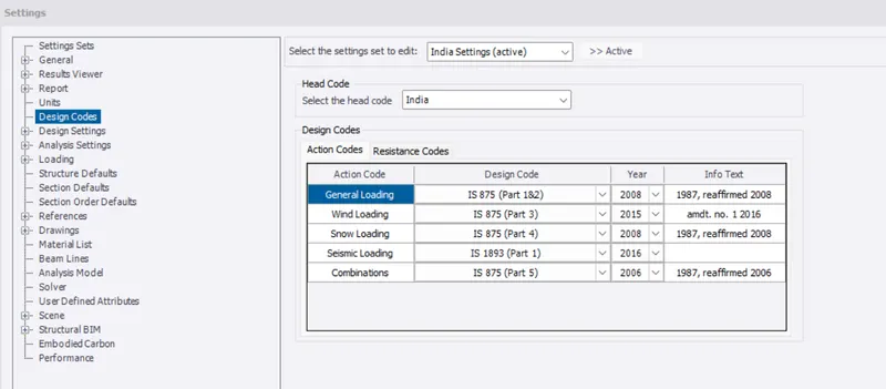
- Setting Design codes and reinforcement details for model. Indian code is assigned as "Head code"
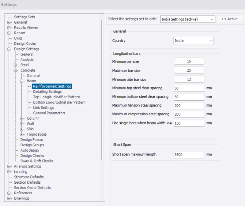
- Beam details checked
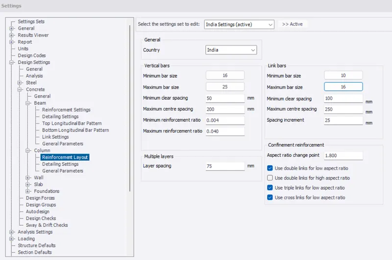
- Column details checked
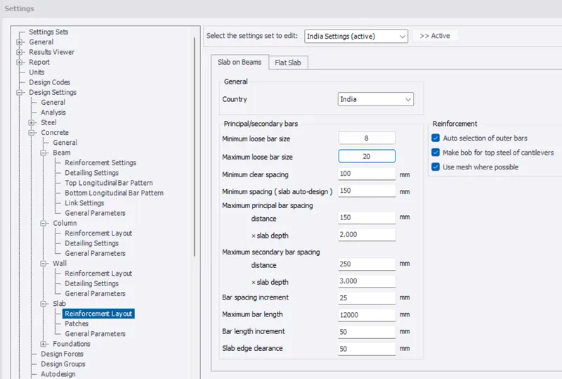
- Slab details checked
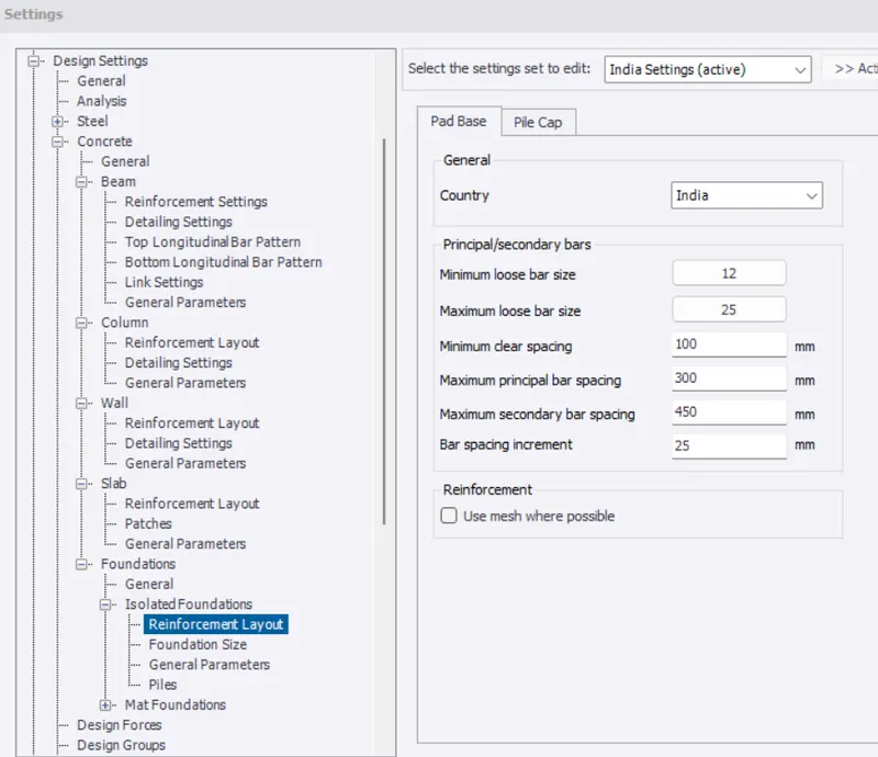
- Foundation details checked
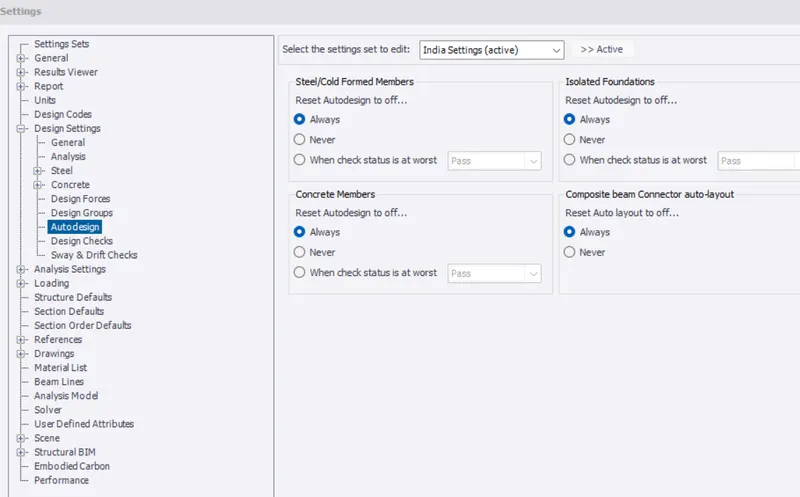
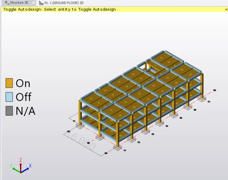
- Autodesign should be set off
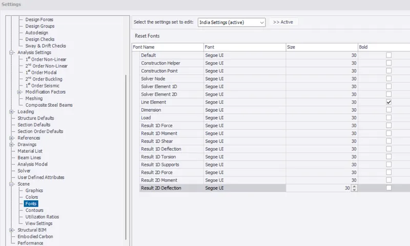
- Font size is set to "30"
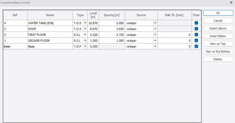
- According to the plan, various levels for RC buildings are assigned.
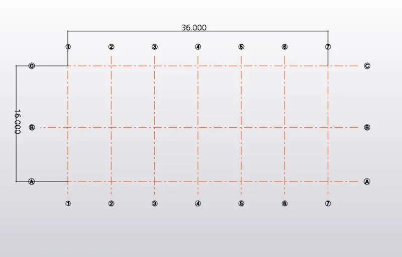
- Draw the grid lines according to the given plan
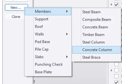
- To create members, Select "Manage property sets" in Home tab
- Select "New"
- Select Concrete column
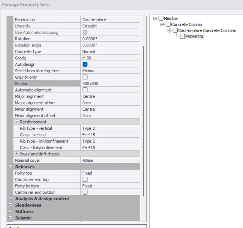
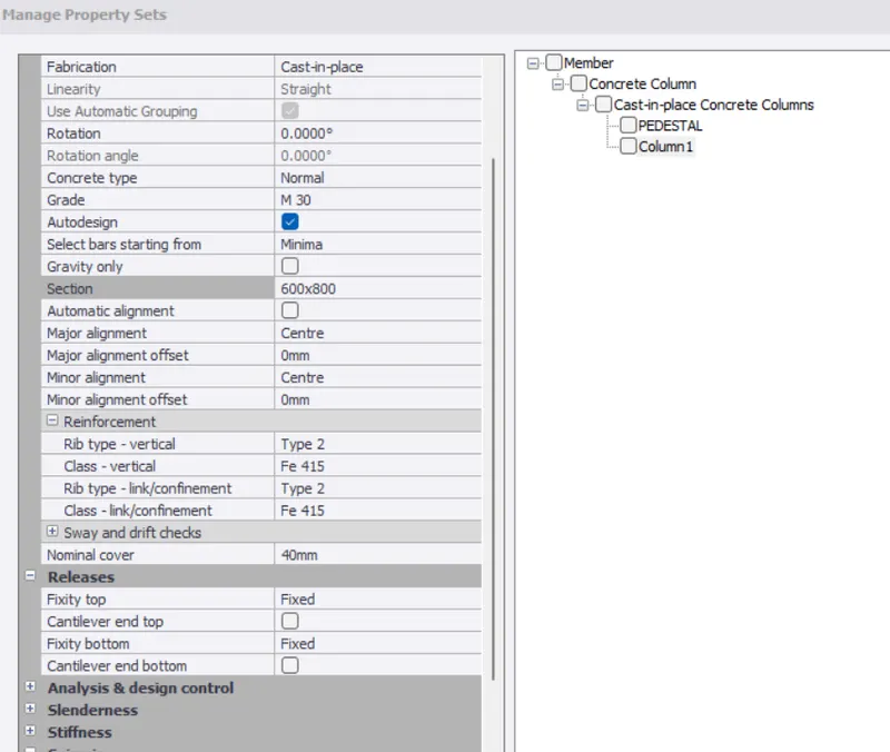
- Pedestal column is created of size 400x800mm and Grade 30
- Column of size 600x800mm is created
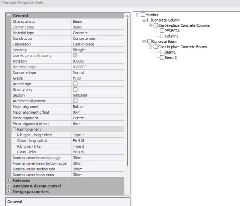
- Primary Beam size of 600x600mm and Secondary beam of size 400x400mm is created
- Now select column in "Model" tab and select pedestal
- Place the pedestal on the grid points
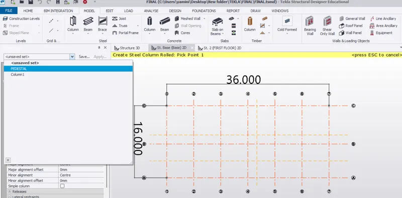
- Place the "Pedestal" in the base level(Top level is ground level and Bottom level is base)
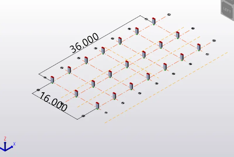
- Now place columns and primary beams according to the given plan
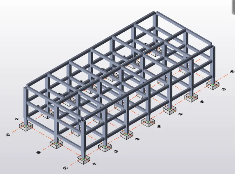
- Place secondary beams as shown below (Ground floor)
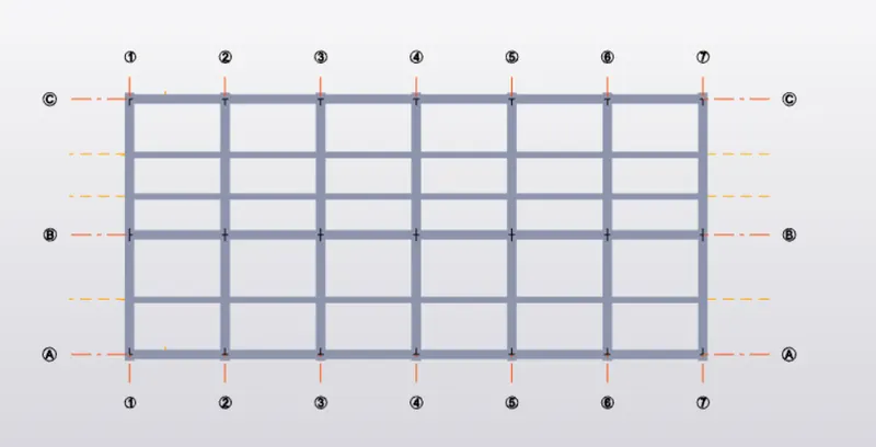
- Place secondary beams as shown below (First floor)
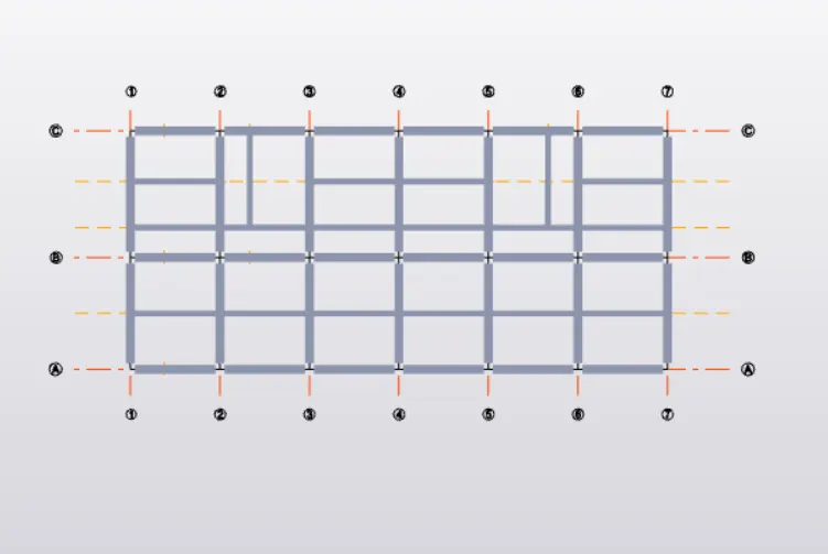
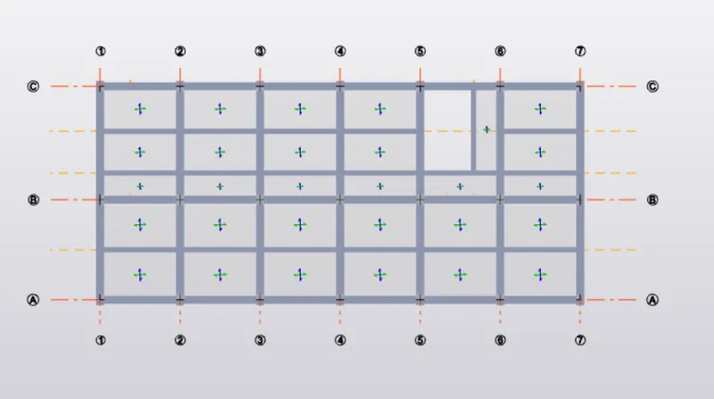
- Place secondary beams as shown below (Roof)
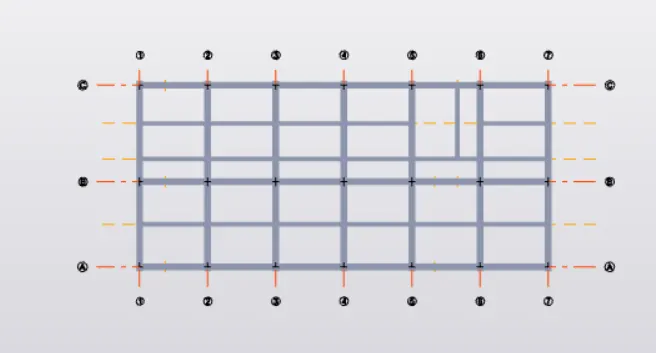
- Validate the model after placing all beams.
- Now select Slab on beams from model tab and place slabs on Groundfloor, first floor and roof
- Set X direction 90 degree and Overall depth of slab as 150mm
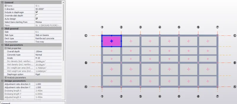
- Slabs on first floor
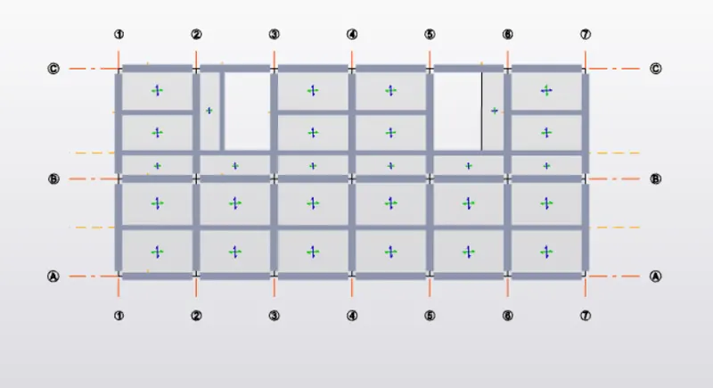
- Slabs on Roof
- Generate load cases
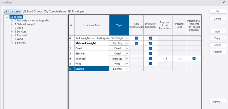
- Generate load combinations
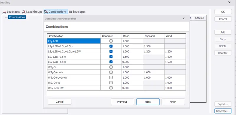
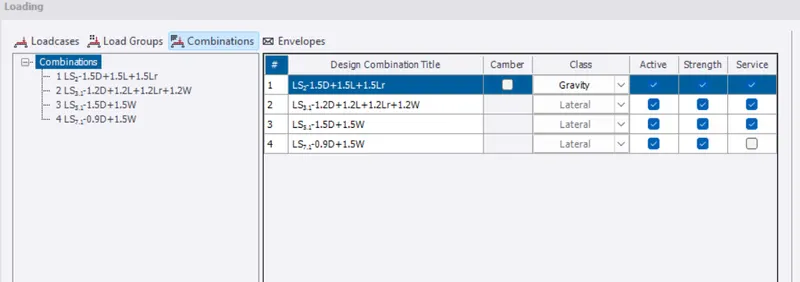
- Apply dead load, live load, Wind load and Seismic load
-
Slab load : Slab modelled in the software
Finishes taken as 50mm, Finishes = 50mm x 24 KN/m^3 = 0.05 x 24 = 1.2 KN/m2
Brick wall width taken as 150mm
Unit weight = 20 KN/m^3
Floor height (Ground floor to First floor) = 3.7m
Brick wall loading for ground floor = 20 x (150/1000) x 3.7 = 11.1KN/m
Floor height (First floor to roof ) = 3.650 m
Brick wall loading for first floor = 20 x (150/1000) x 3.650 = 10.95KN/m
Roofing load based on purlin size :1.5KN/m^2
Water tank load = 2mx10 = 20KN/m^2Ceiling loading 0f 0.3KN per sq m
-
- Select dead load at the bottom
- Now select area load from panel load (Load tab)
- Select area load = 1.2KN/m2 in ground floor and first floor and apply it
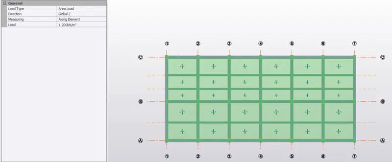
- Now apply brick load to Groundfloor, Firstfloor
- Select "Full udl" in load tab and apply brick load = 11.1KN/m for groundfloor and First floor = 10.95KN/m
- Now select Line load and draw inside walls of brick load = 11.1KN/m2
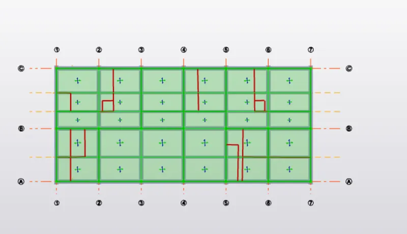
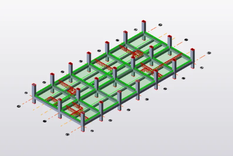
- First floor
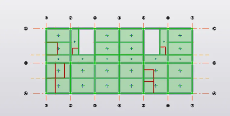
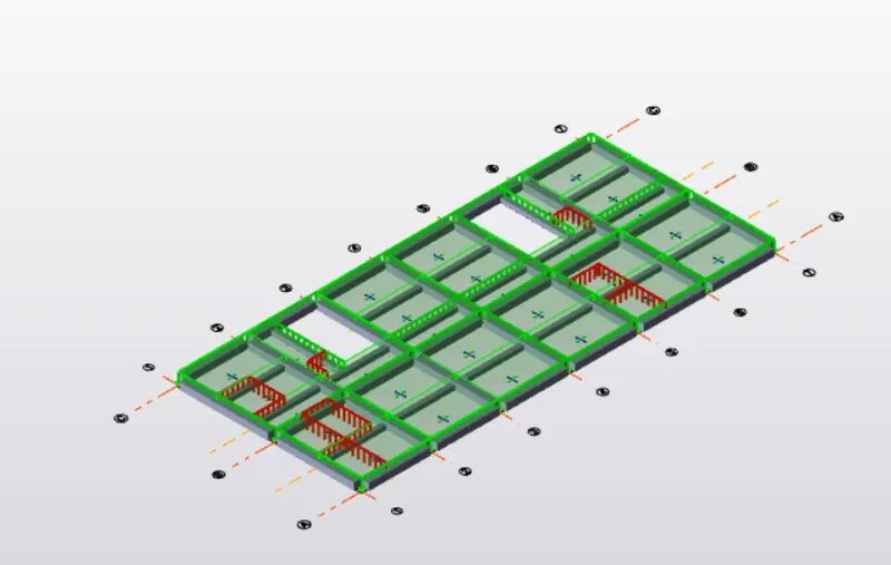
- 1.5KN/m^2 load applied on Roof
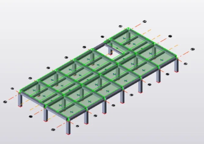
- Live loads applied on Office building according to the IS 875part 2
-
Work areas without machinery/equipments = 2.5KN/m^2
Work areas with machinery/equipments = 7KN/m^2
Staircase : 4KN/m^2
Toilets : 2KN/m^2
Canteen : 3KN/m^2
Store room : 2.4KN/m^2
Conference room : 4KN/m^2
Meeting room : 4KN/m^2
Office room : 4KN/m^2
Manager room : 4KN/m^2
Corridor : 4KN/m^2
-
- Now click on imposed loads at bottom
- Select area load in the panel loads
- Assign loads on the all floors according to the IS 875part 2
- Add wall panels to the building
- Now apply wind load
-
Wind speed taken as 50m/s
Terrain category taken as 2
Vb = Basic wind speed which is given as 50m/s
Normally basic wind speed is selected from appendix A of code book IS 875 III which is given based on wind speed in various cities
Design wind speed Vz= Vb*K1*K2*K3*K4
Where Vz depends on risk level, terrain roughness, height, size of structure, local topography
K1 = Probability factor
It is taken from table 1 of IS 875 III
Life of structure is taken as 50 yrs and wind speed is given as 50m/s. Based on this K1 =1
K2 = Terrain, height, structure factor which is taken from table 2 = 1
K3 = Topography factor which is taken as 1 (θ<3 = 1 and θ>3 = 1 to 1.36)
K4 = Importane factor for cyclonic region K4 is taken as 1.15
Where K4 = 1.3 Structure for post cyclonic importance
= 1.15 Industrial structure
= 1 All other structure - Design wind speed Vz = Vb x K1 x K2 x K3 x K4 = 50 x 1 x 1x 1 x 1.15 = 57.5m/s
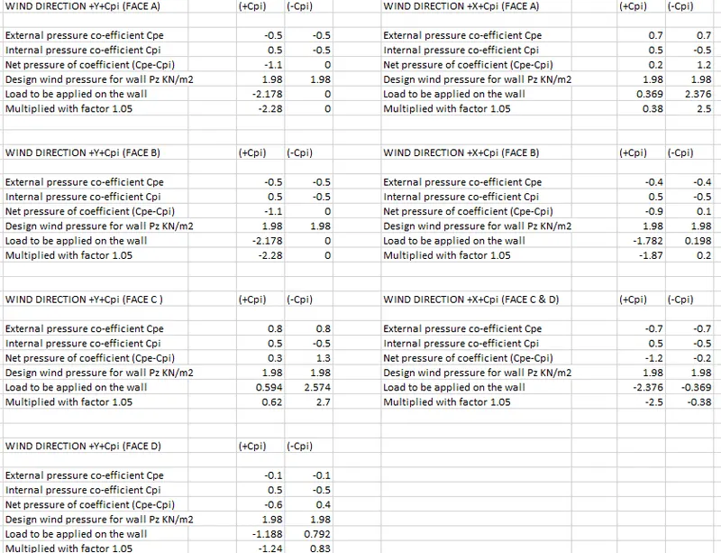
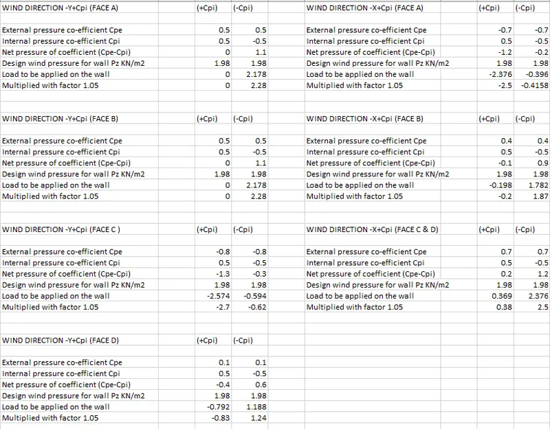
- Design wind pressure = Pz = 0.6 x Vz^2 = 1983.75N/m2 = 1.98KN/m2
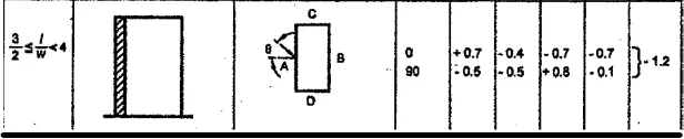
- Length = 3.6m, Width = 1.6m, Height = 9.35m
- L/W = 2.25 and H/W = 5.84
- External pressure coefficients for wall is taken from table 5 IS 875 III (H/W=5.84)
-
- Open load tab and select load cases
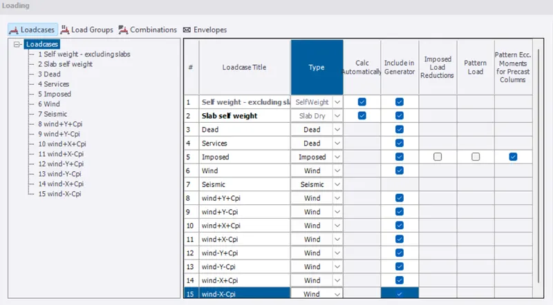
- Add following load cases
- Wind load
- wind+Y+Cpi
- wind+Y-Cpi
- wind+X+Cpi
- wind+X-Cpi
- wind-Y+Cpi
- wind-Y-Cpi
- wind-X+Cpi
- wind-X-Cpi
- Select the frames to be load applied
- Go to load, select area load
- At bottom select the combination load and apply it on walls and roofs
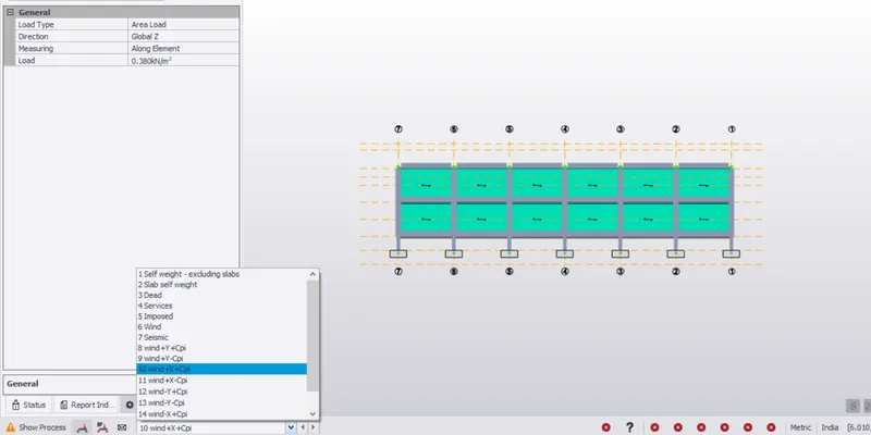
- Now apply Seismic load
- Select seismic wizard under seismic loads
- Select code spectra and click on next
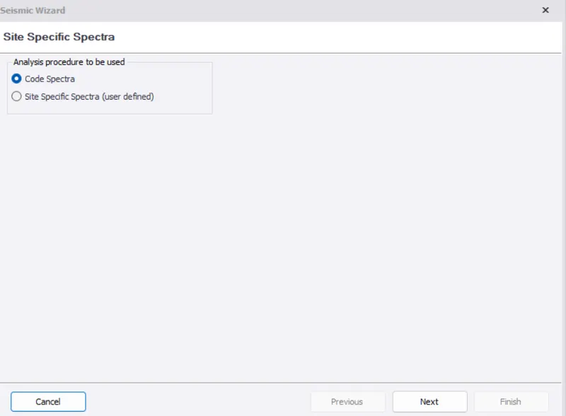
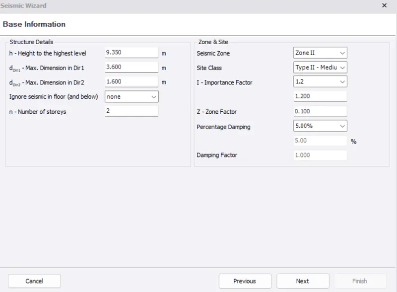
- Check the dimensions of the building and other details
- Zone is set as Zone II, site class a Type II medium, Importance factor as 1.2
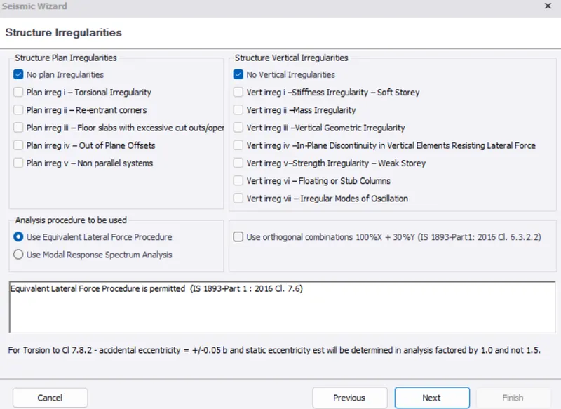
- Set structure irregularities and use equivalent lateral force procedure
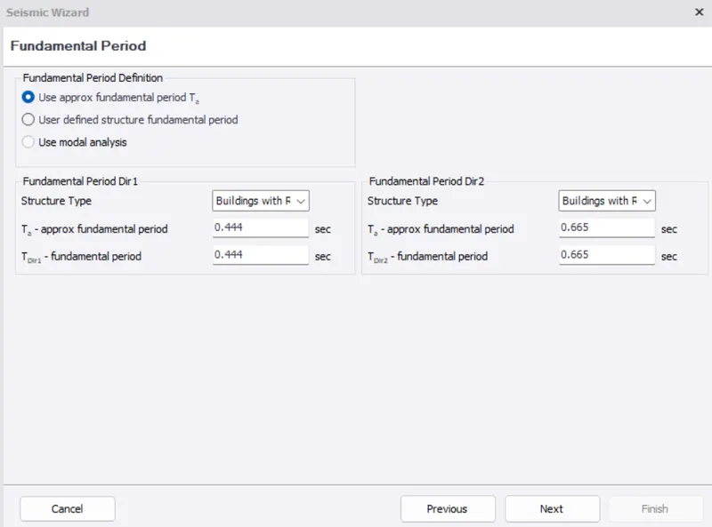
- Use 'Moment frame systems' for RC building with OMRF in Seismic force resisting system
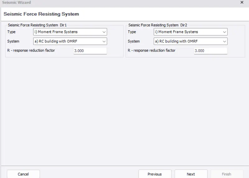
- Include all the loadcases : Self weight- excluding slabs, Slab self weight, Dead, Services and Imposed
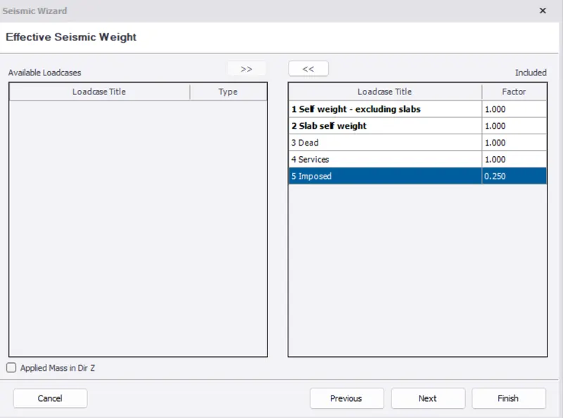
- Select 'Delete all previously generated combinations in combination generator
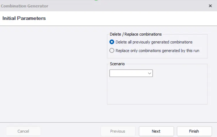
- Select finish
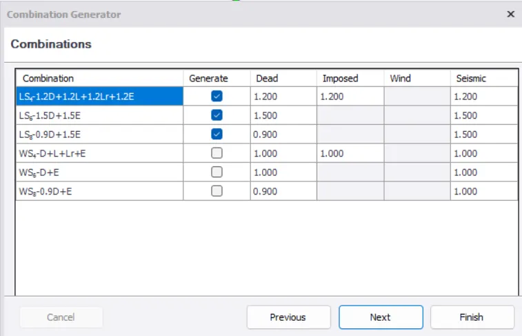
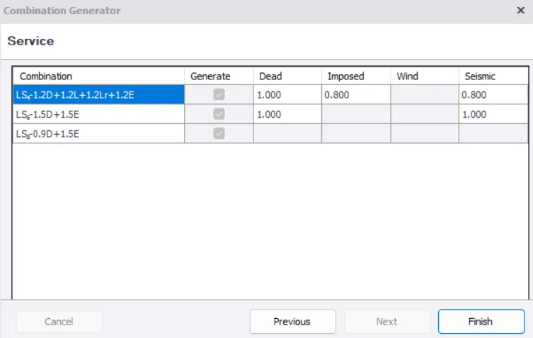
- Click Combinations on load tab to check the generation of seismic loads and then click generate
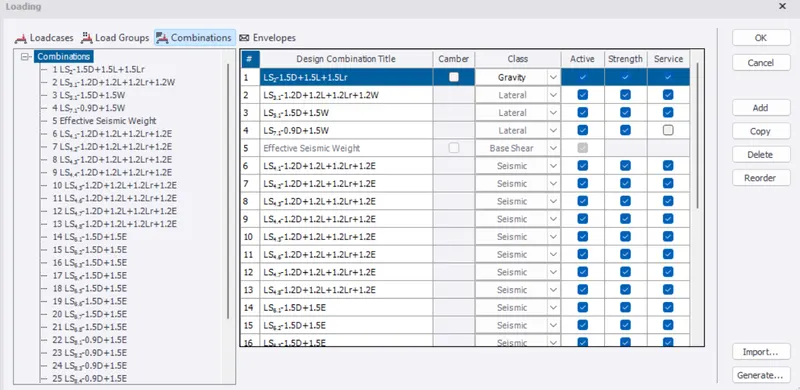
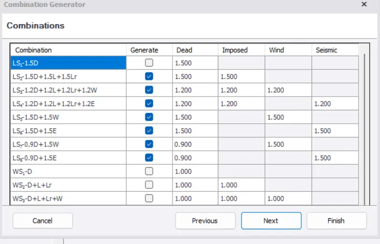
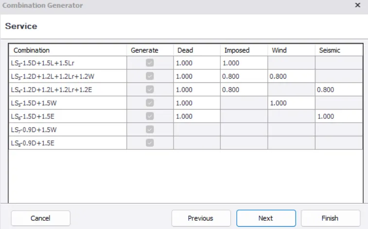
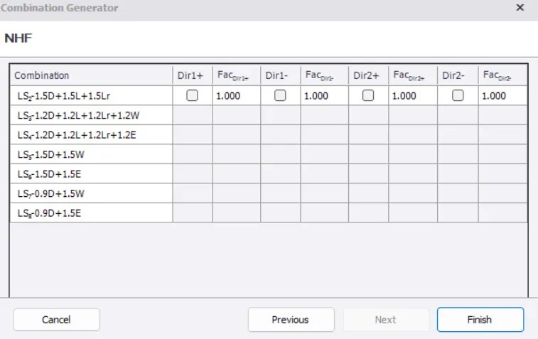
- Select finish
- Select Review and click on "Auto design check"
- Go to analyse tab and click on 1st order linear analysis
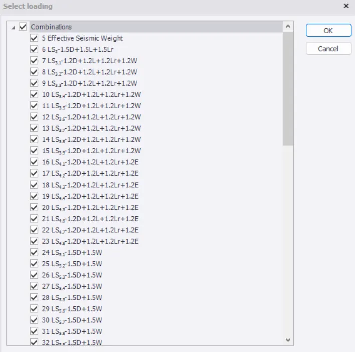
- Click ok and select "RESULTS"
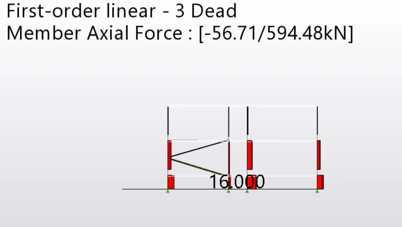
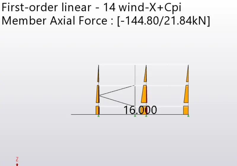
- Select "Axial force" in the results tab to get diagrams under axial loads and check under various combinations
- Example
- Example
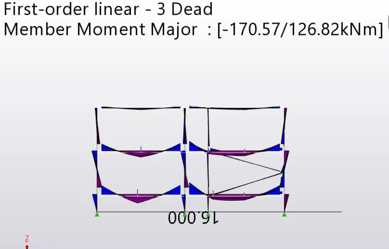
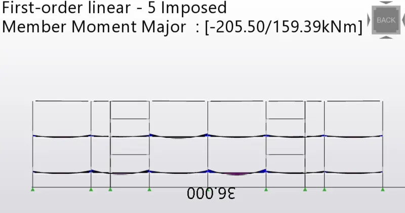
- Select "Moment major" in the results tab to get diagrams under moment and check under various combinations
- Example
- Example
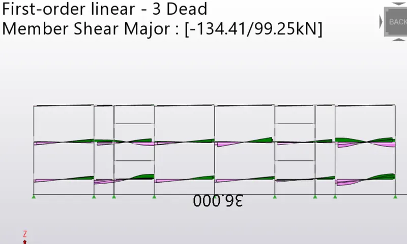
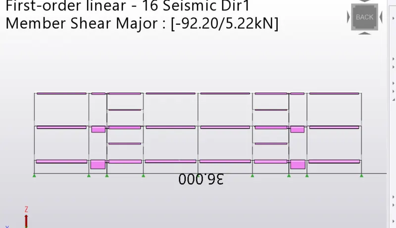
- Select "Shear major" in the results tab to get diagrams under moment and check under various combinations
- Select "Deflections" in the results tab to get diagrams under moment and check under various combinations
- Example
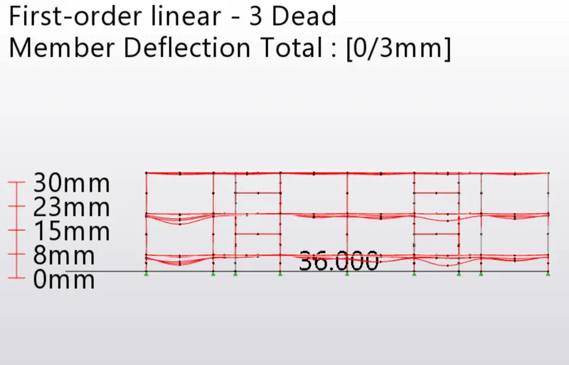
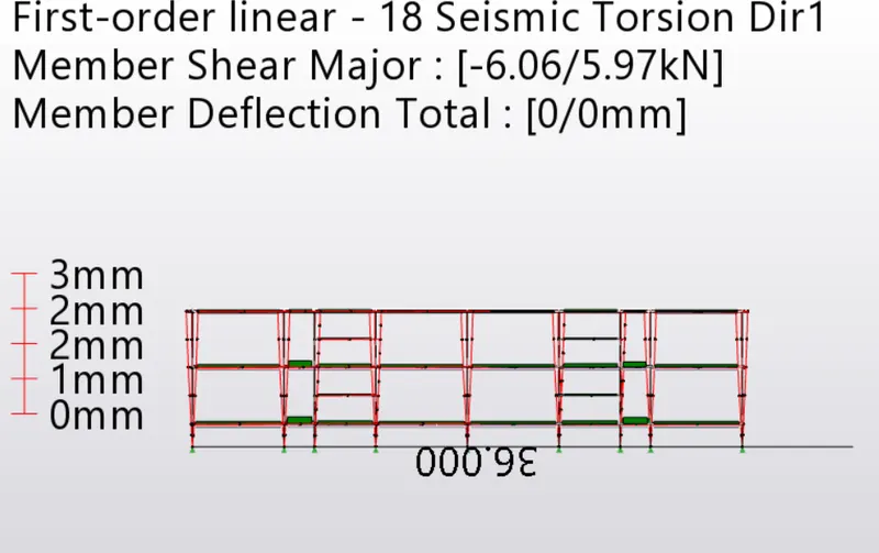
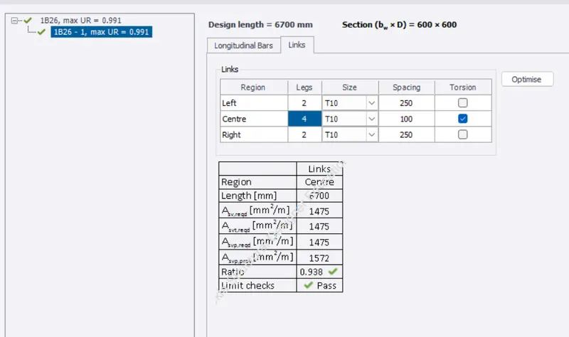
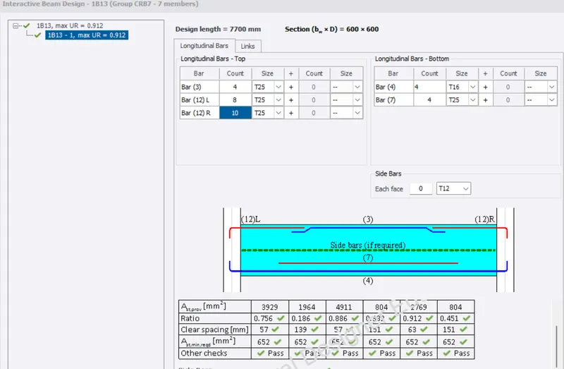
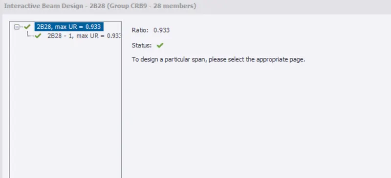
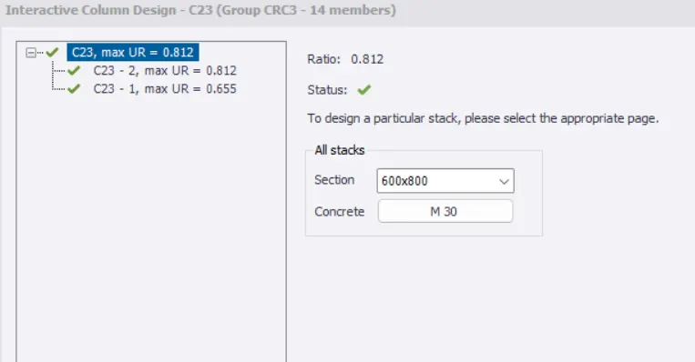
- Now check the column and beam reinforcement by selecting interactive design
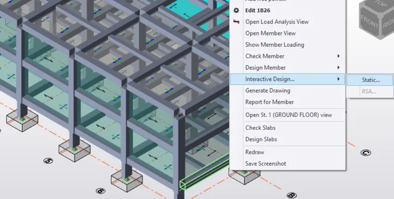
- Change member reinforcement wherever failure occured
- Sizes of columns or beams can be changed by double click on each member
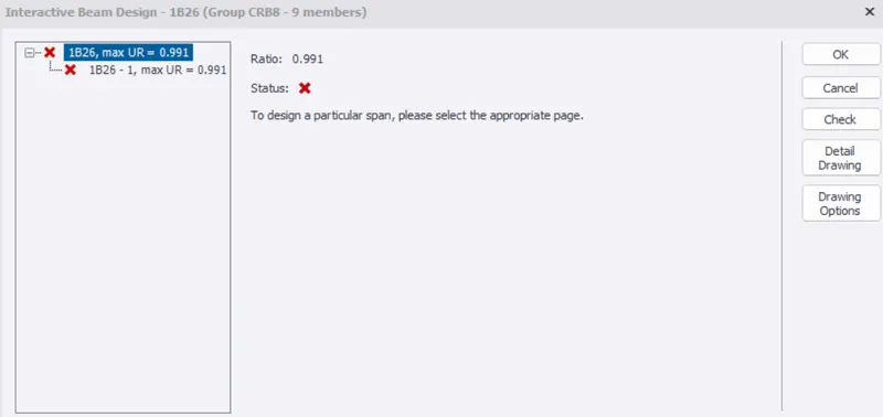
- After changes done in beam reinforcement
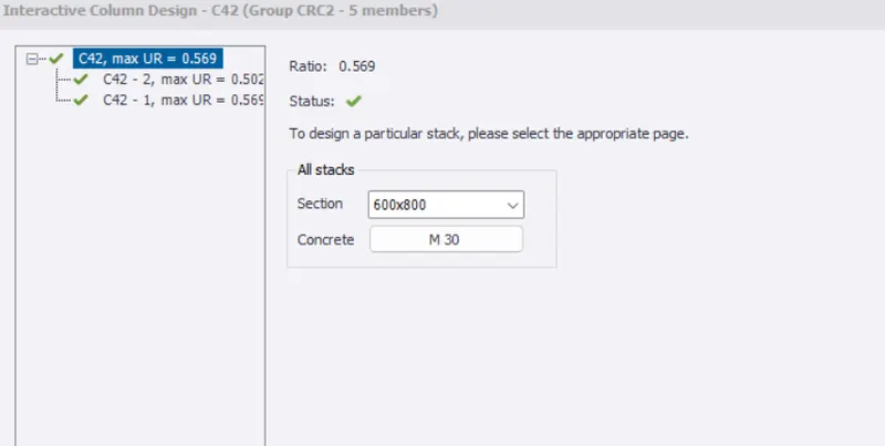
- Similarly columns are checked
- Now go to report tab and select "Building design"

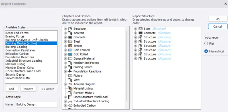
- Click on Model report settings and select necessary content for report generation
- Example : In "Structure"
Select level, loading, loadcase summary, combination and seismic load
- Example : In "Structure"
- Now select Show report
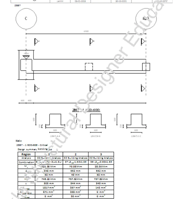
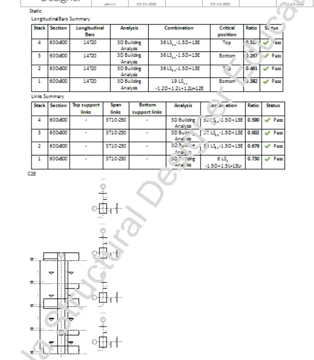
- Some of the results shown below
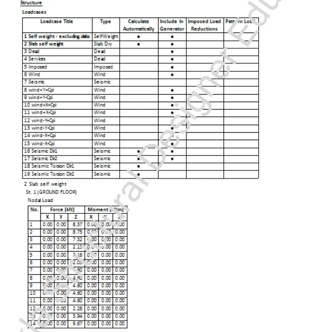
- Similarly generate analysis
- Click on Model report settings and select necessary content for report generation
- Example : Analysis
Select element and move it to right side 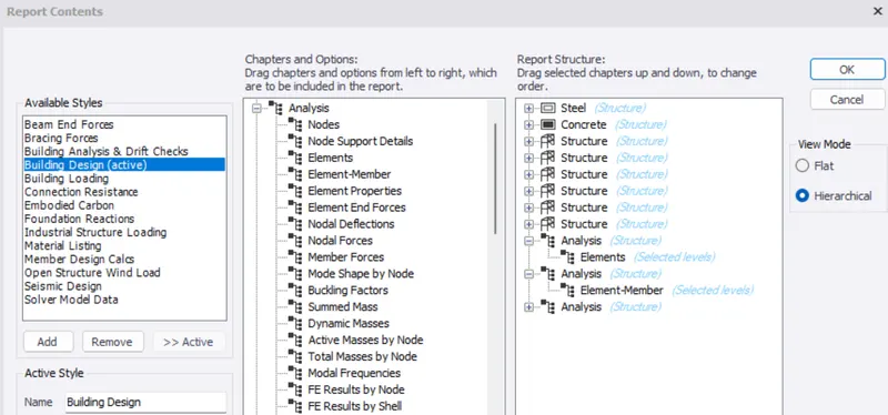
- Click on show report and some of the results shown below
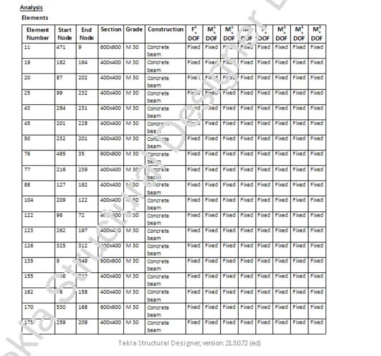
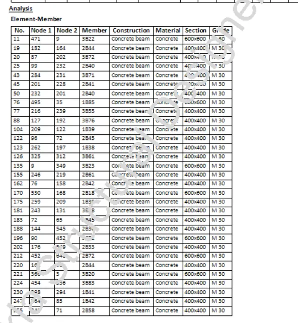
- Example : Analysis
RESULTS : Wooden columns and Truss at roof level added for the model