Project 2_Analyze and Design the RC office building as per IS standard code in TEKLA STRUCTURAL DESIGNER
1)
Aim :-
Develop general arrangement for the RC office building. Analyze and design the building as per IS standard code in TEKLA STRUCTURAL DESIGNER. Refer the attached plan and elevation. The building to be designed for dead, live, wind and seismic loading.
Report of each member to be generated and extract drawings for structural plans, beam reinforcement details from the software
Procedure :-
* Open Tekla Structural Design Software
* Go to Home – Settings to check the default settings
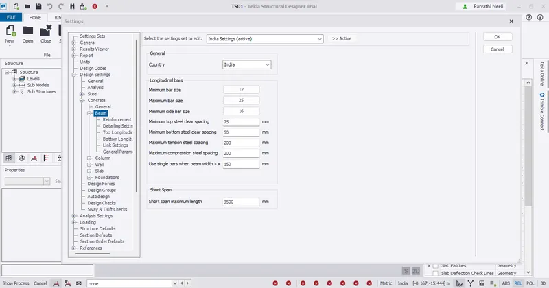
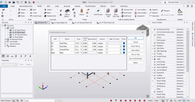
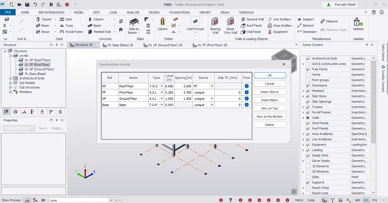
* Go to Model – Construction levels to create 4 levels – Base, GF, FF , RF
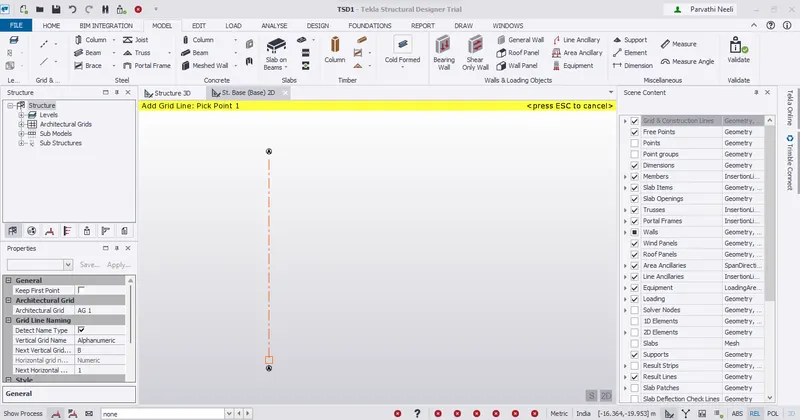
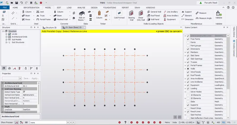
* Model – Grid lines to draw the grid lines
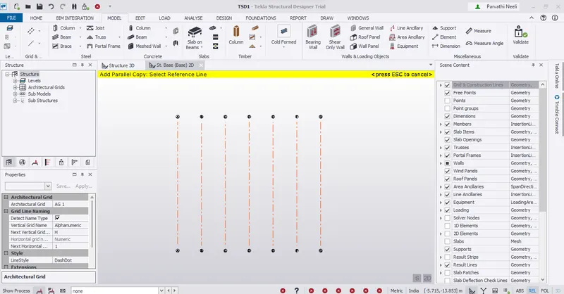
* Draw parallel grid lines at 6m spacing
* Now draw horizontal grid lines by using perpendicular option
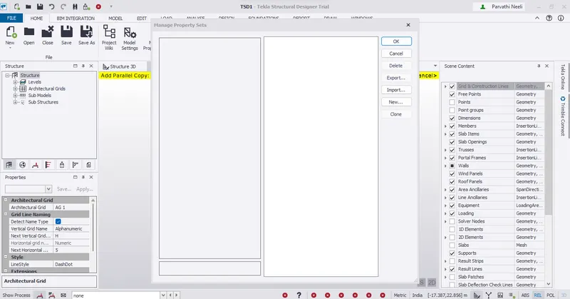
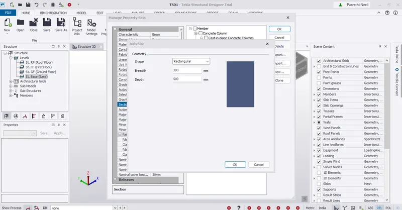
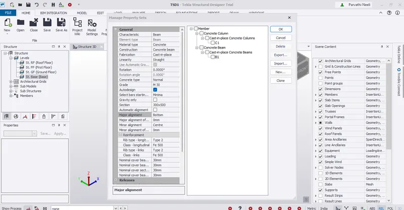
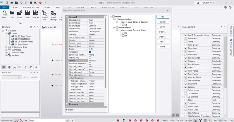
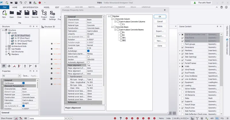
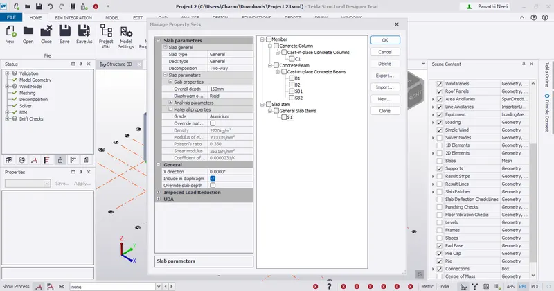
* Home – Manage Property Sets
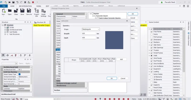
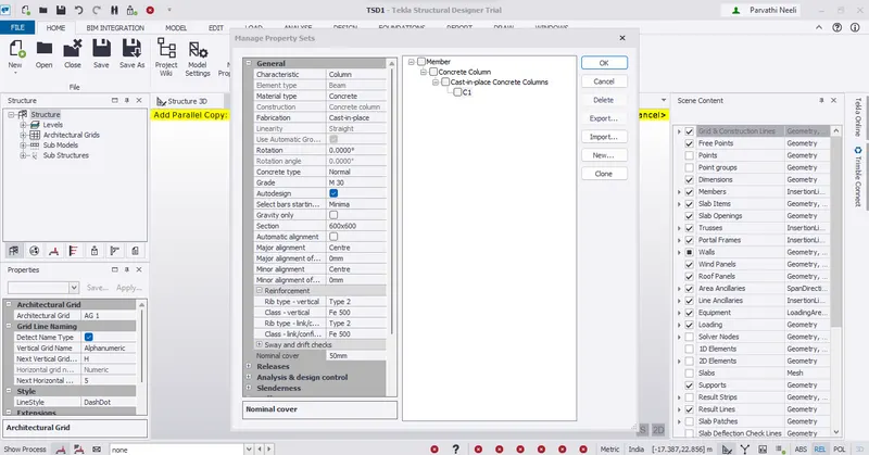
* Go to Base level
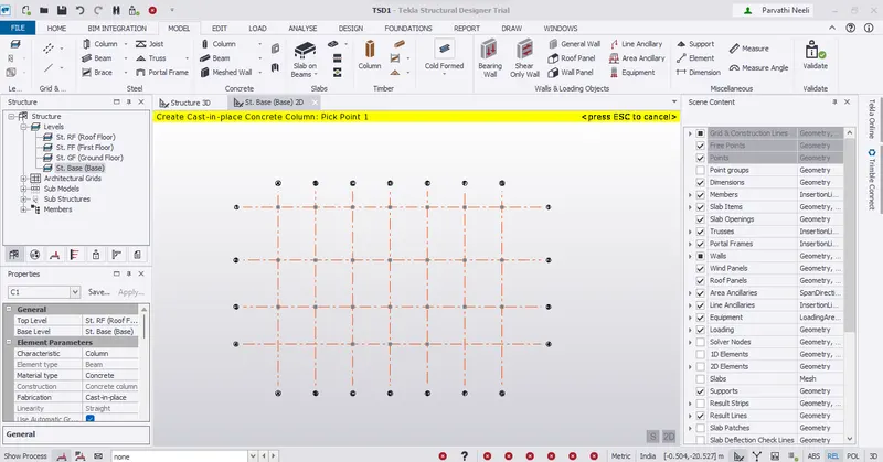
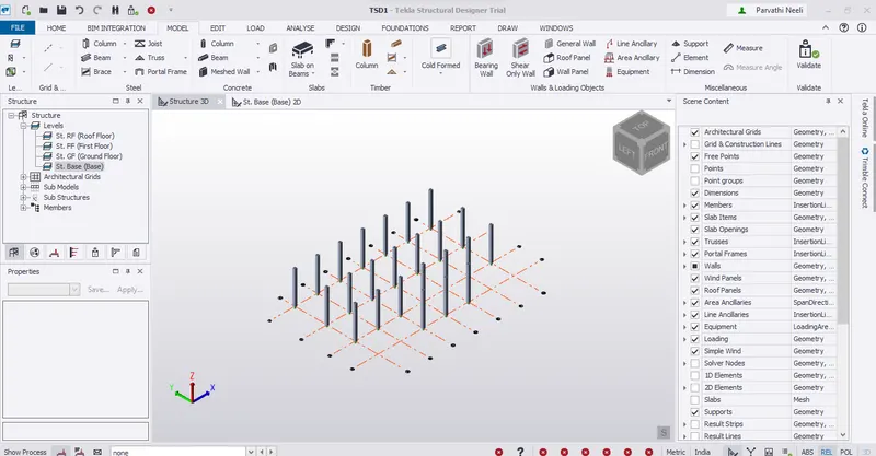
* Model – Concrete column and start placing columns in the grid intersections
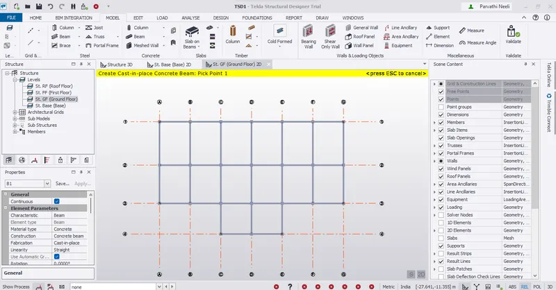
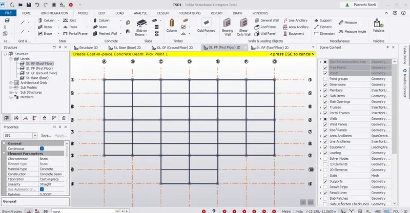
* Then place the beams in the ground floor
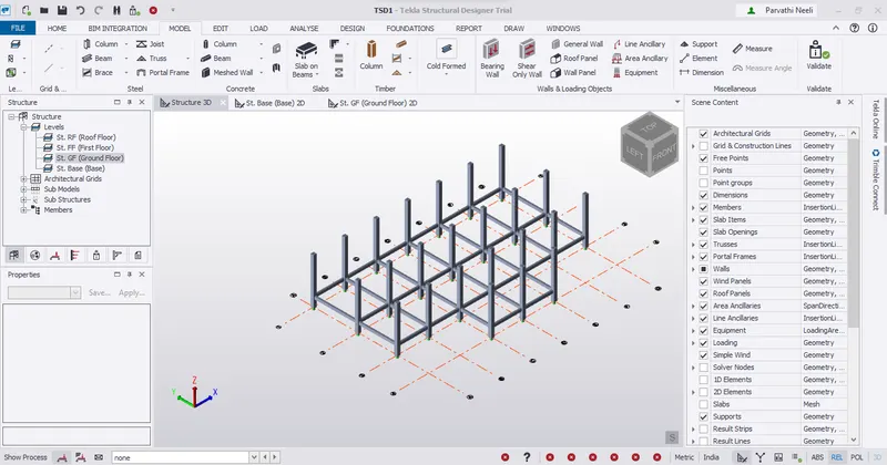
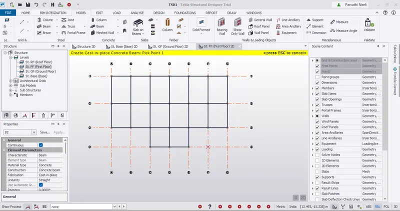
* Repeat the same for first floor too
 \
\
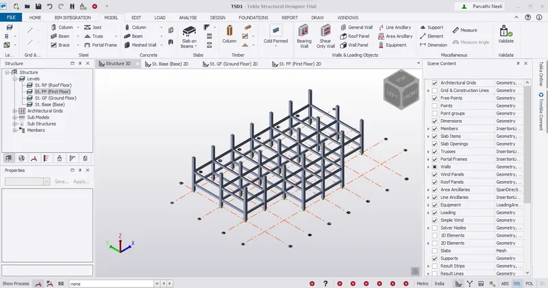
* Go to Construction levels and set the roof level source as first floor
* Later delete the portico beams by changing it to unique again
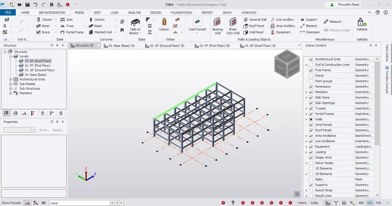
* Now when you try to delete the portico beams notice that the first floor beams also get deleted
* So change the RF source to unique and then delete the beams
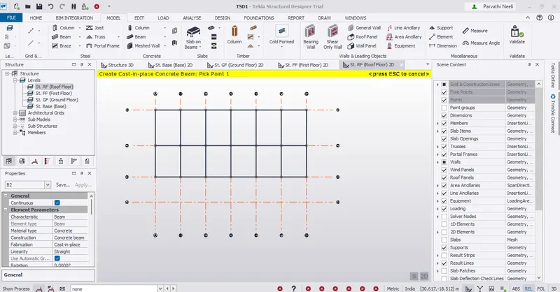
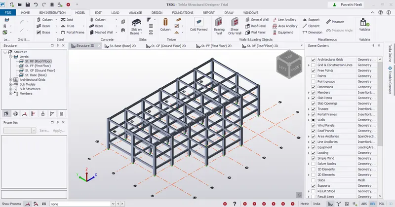
* Now model secondary beams by drawing appropriate construction lines
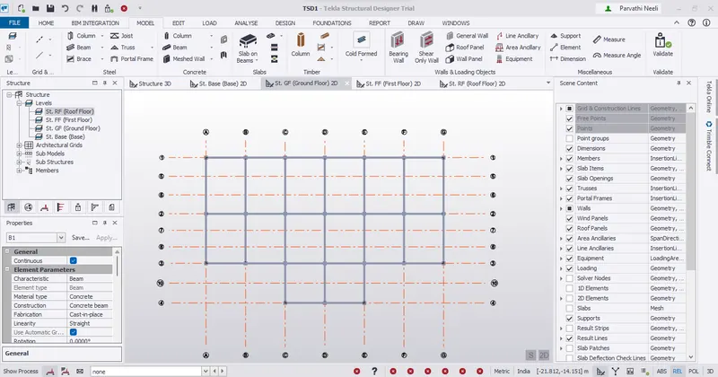
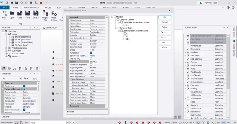
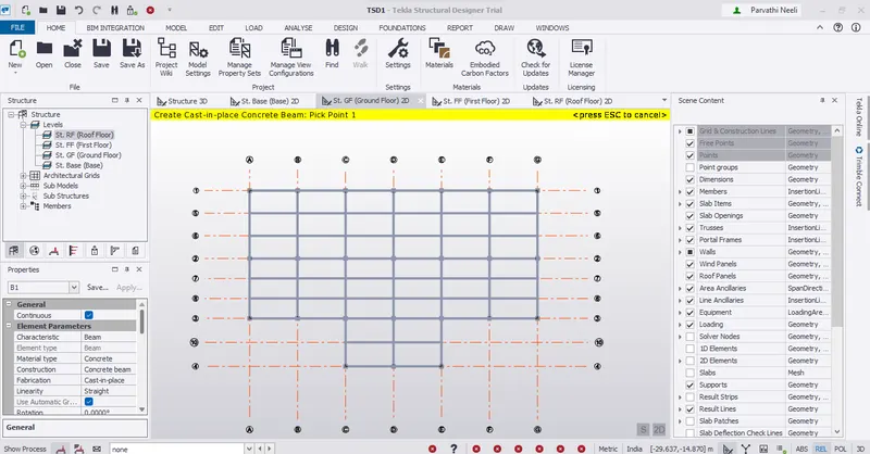
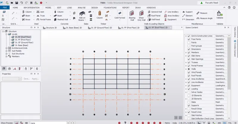
* Similarly move to the FF and RF level and model secondary beams
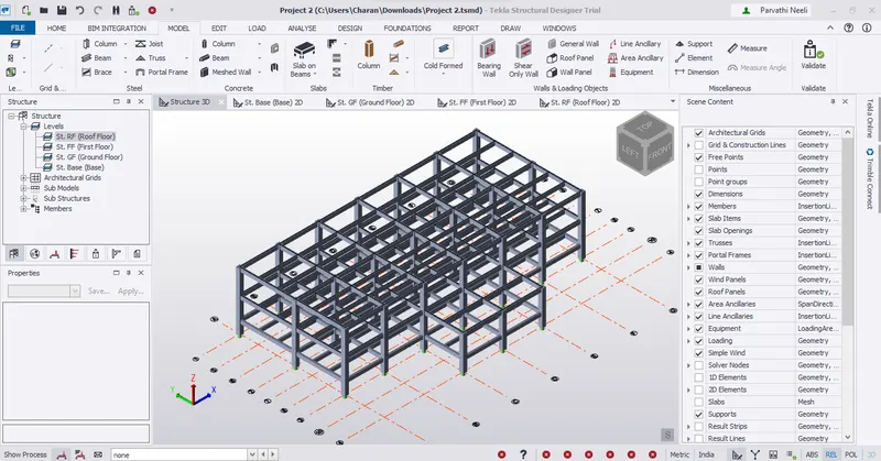
* Validate the model for any errors in beams / columns
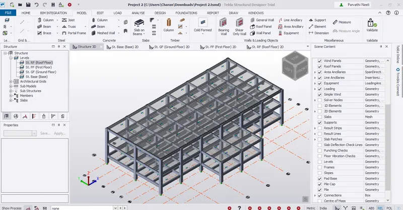
* Now slabs on beams are modelled
Load Calculations :-
Dead load
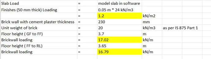
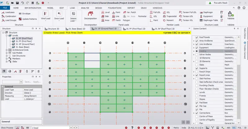
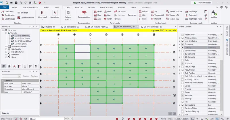
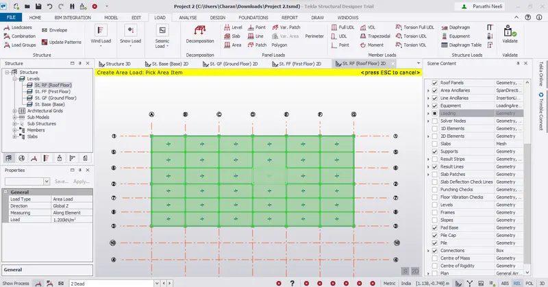
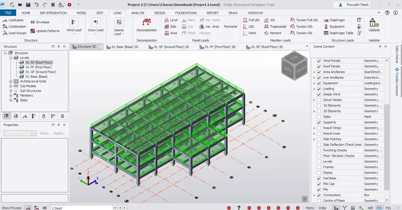
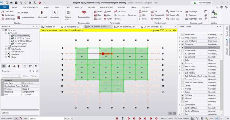
* Lets now apply the floor finish load and brick loads to the panels and members
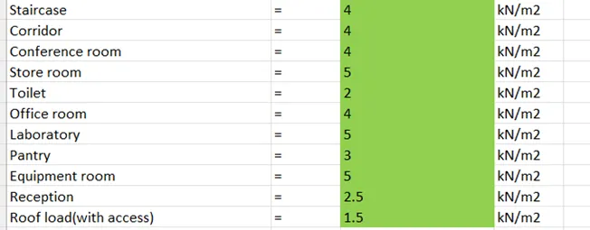
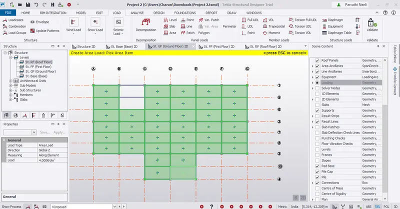
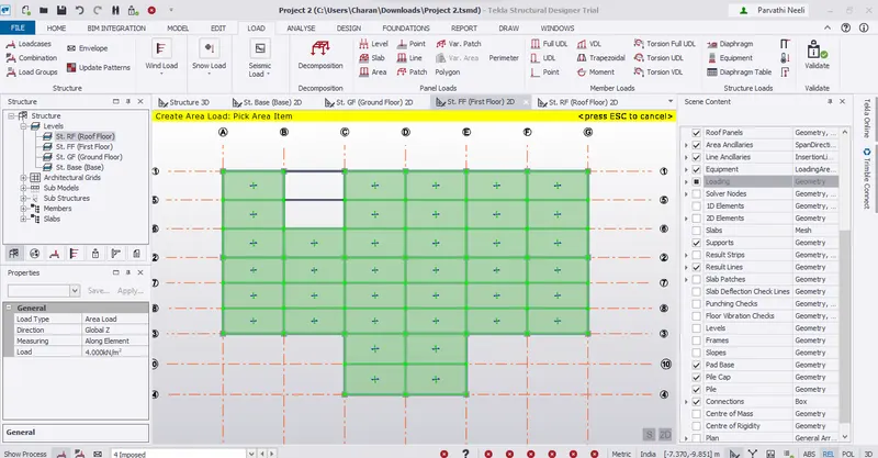
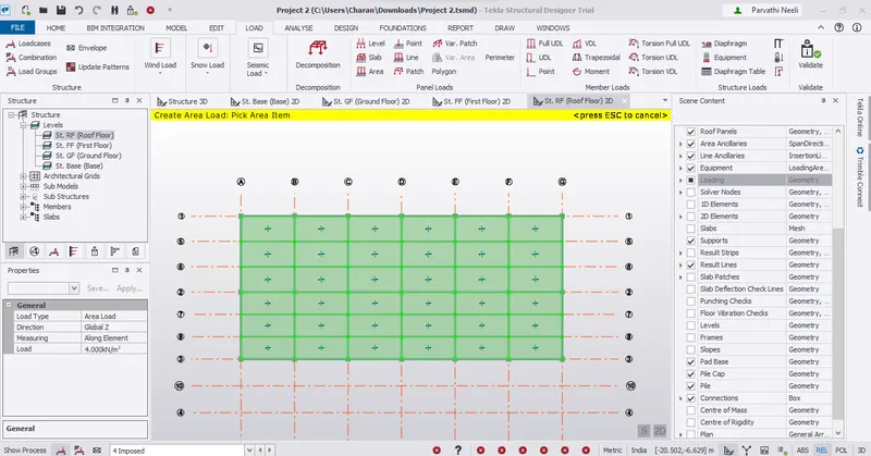
Live load :-
Wind Load :-
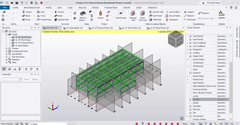
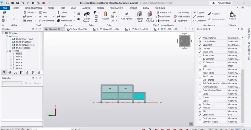
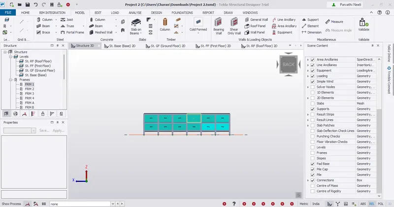
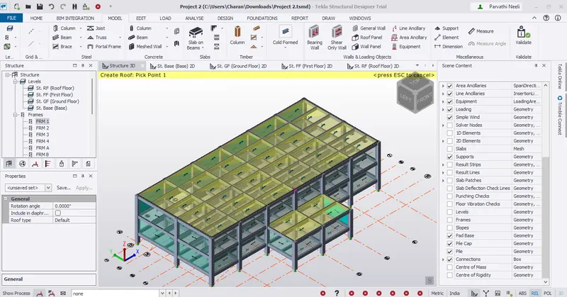
* Create Frames and then model the wall and roof panels
Calculation :-
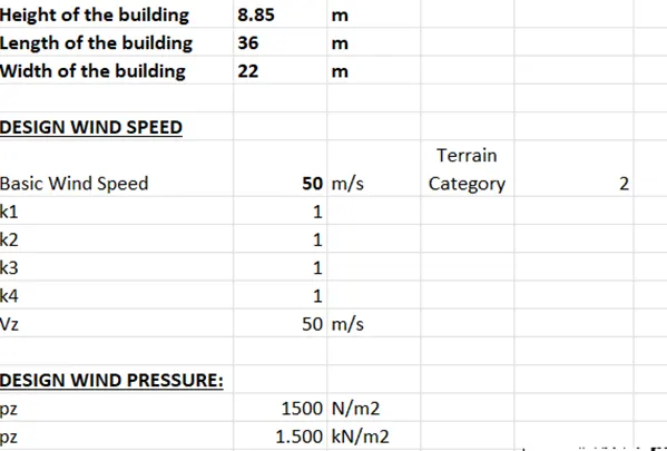
On Walls :-
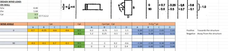
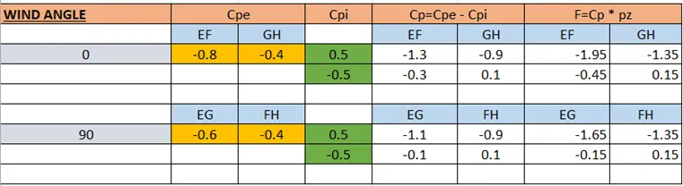
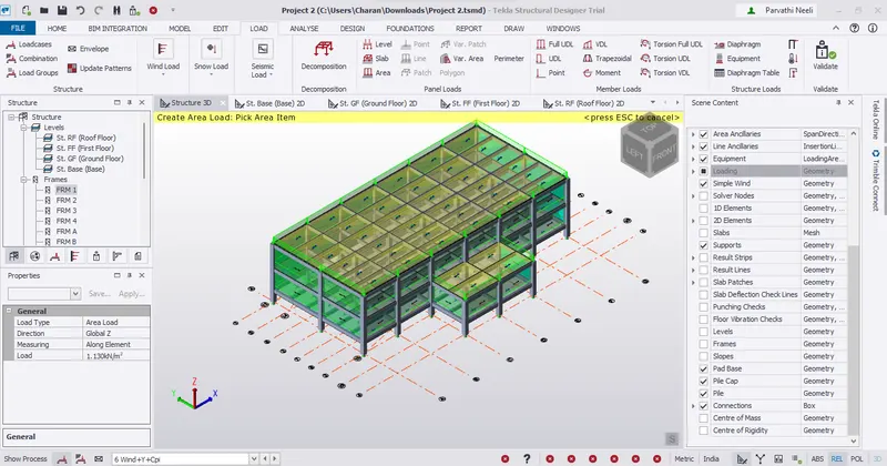
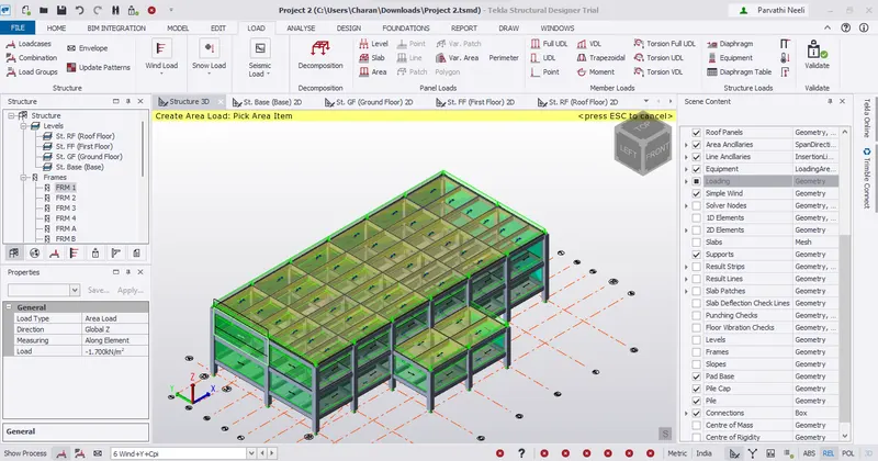
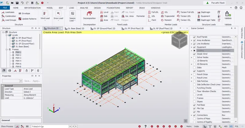
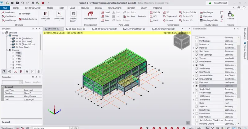
* Go to Load – Loadcases and add the wind loads
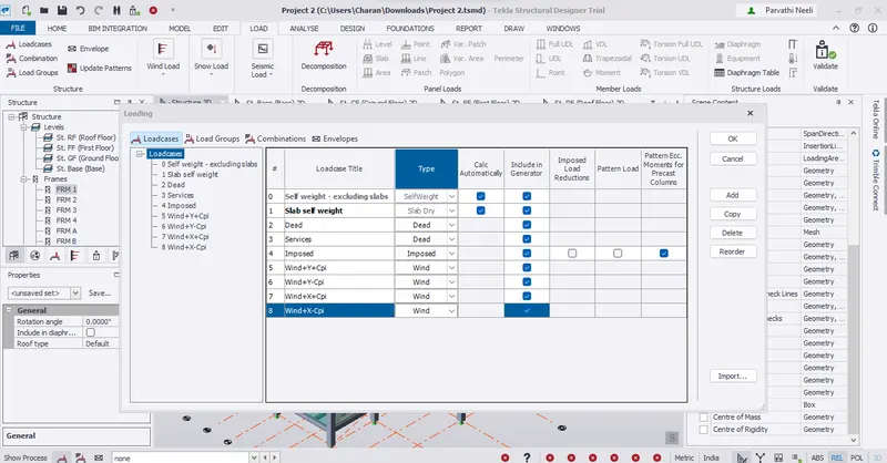
Wind+Y+Cpi :-
On Walls :-
On Roofs :-
Wind+Y-Cpi :-
On Walls :-
On Roof :-
Wind+X+Cpi :-
On Walls :-
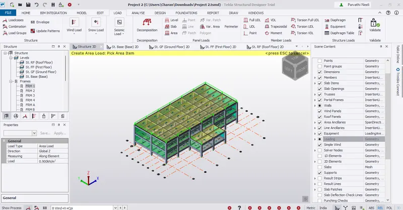
On Roof :-
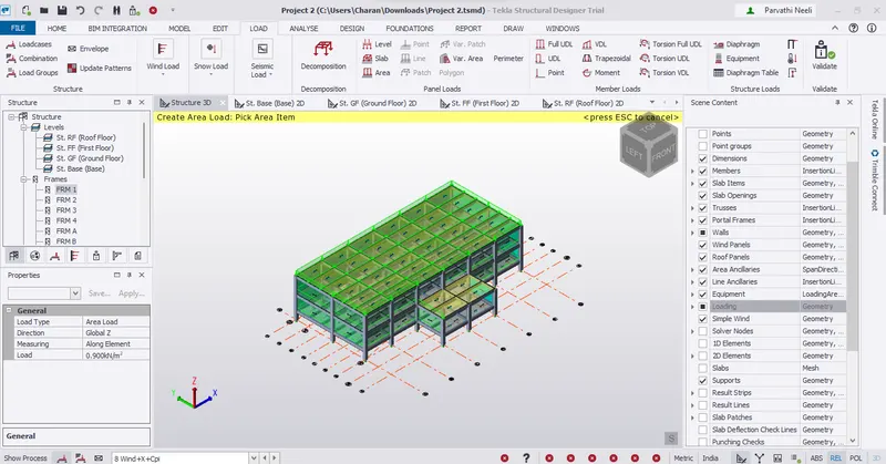
Wind+X-Cpi :-
On Walls :-
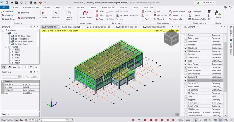
On Roof :-
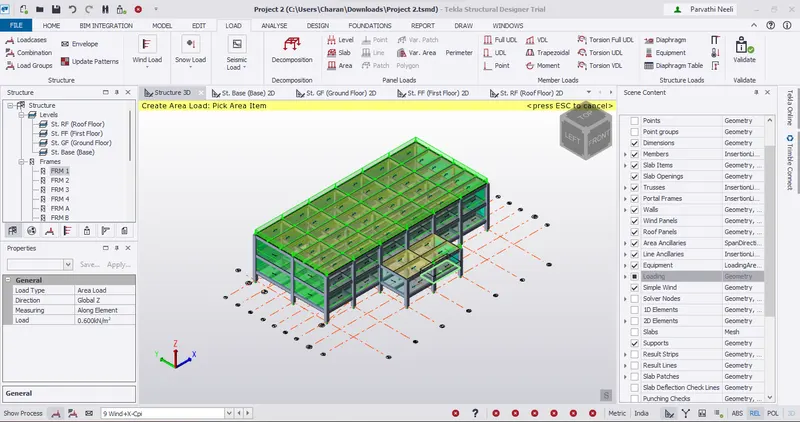
Seismic Loads :-
* Load – Seismic load – Seismic wizard
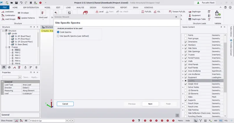
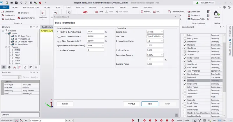
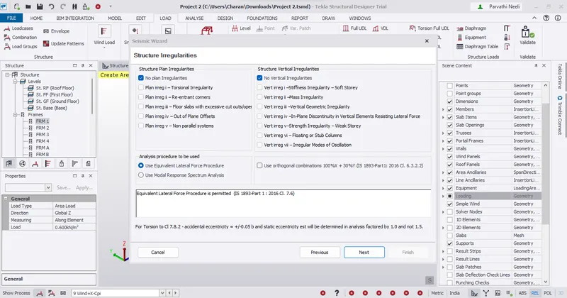
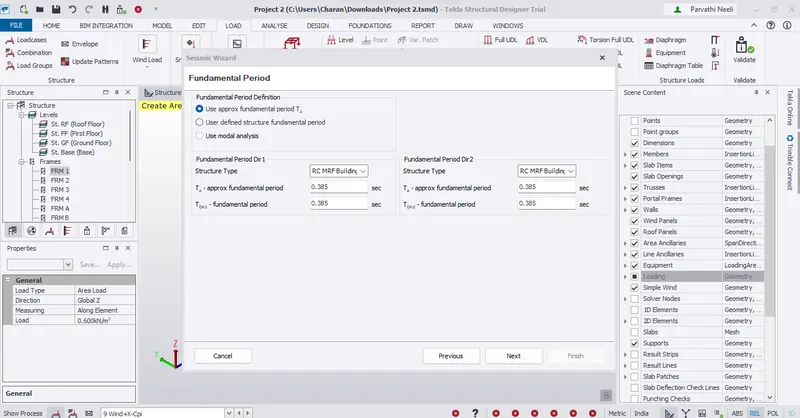
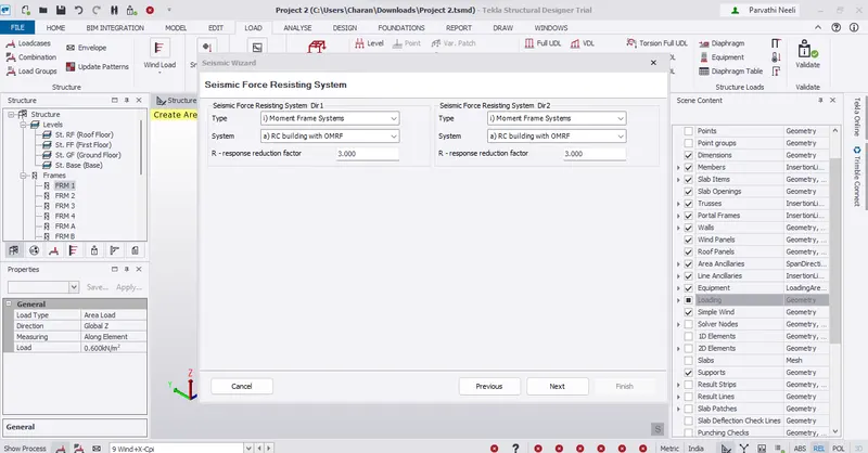
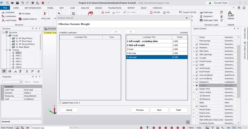
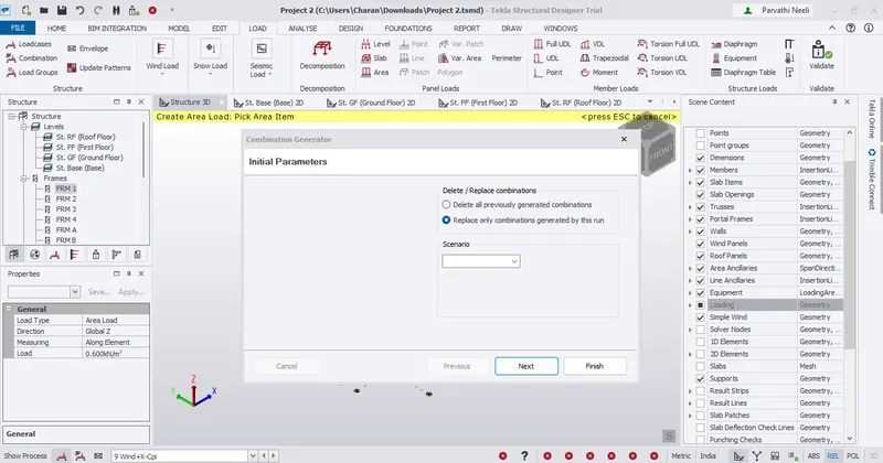
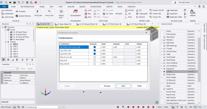
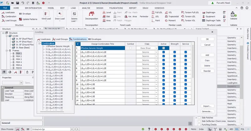
* Now the combination generator opens.
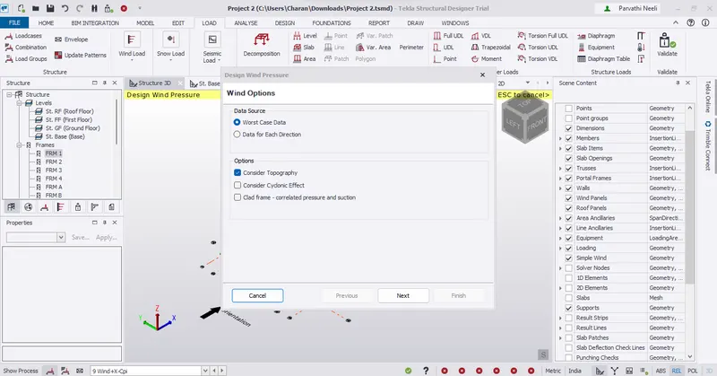
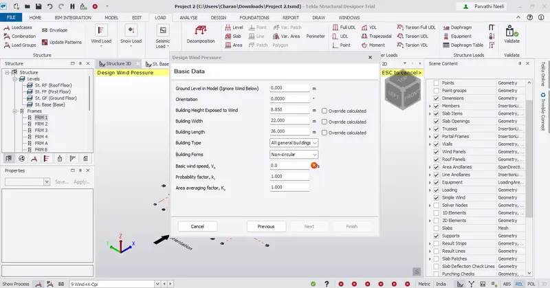
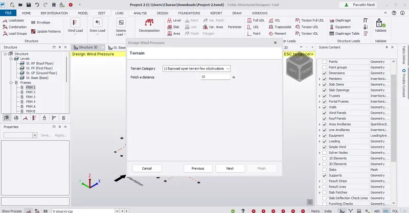
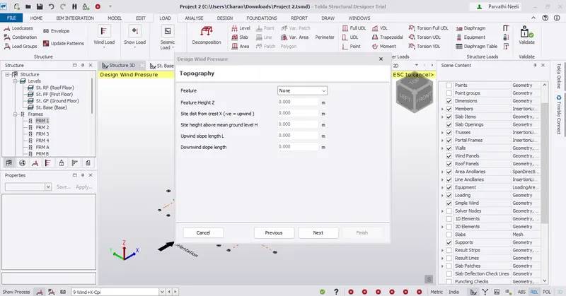
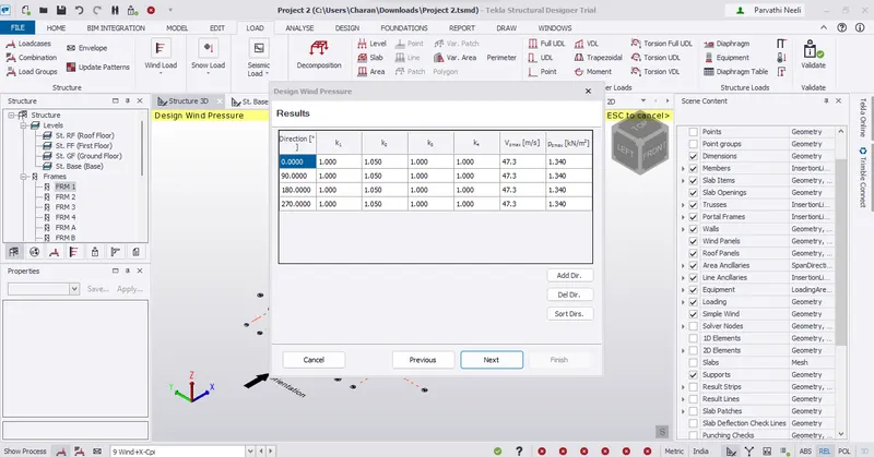
Wind Pressure :-
Analysis :-
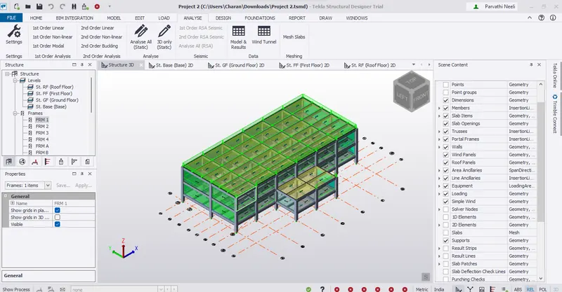
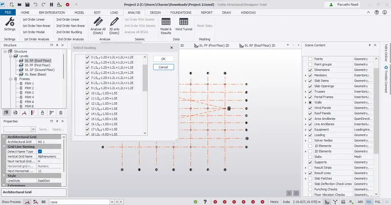
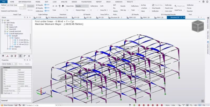
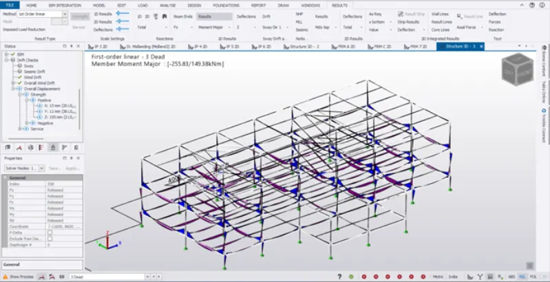
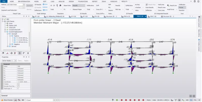
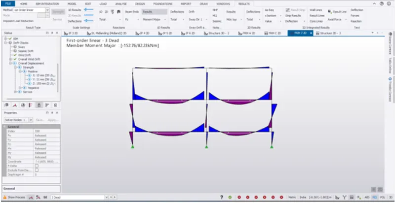
* Now Analyze the model - First order analysis
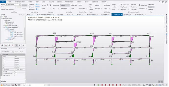
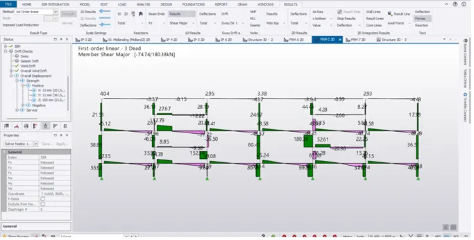
Member Design :-
Slab :-
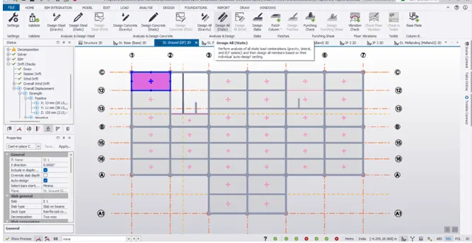
* Right click on the slab and select check panel
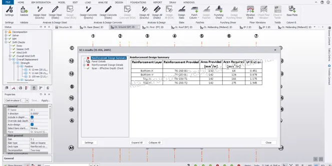
* Now increase the bar size and decrease the spacing to pass the slab
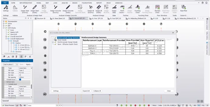
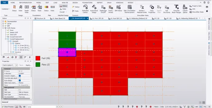
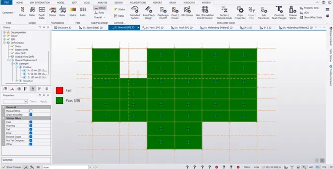
* Using Review – Copy properties , copy the property of the slab that has passed to all the remaining slabs and check panel one by one
* Similarly repeat for all the slabs
Beam And Column :-
* Click on any frame
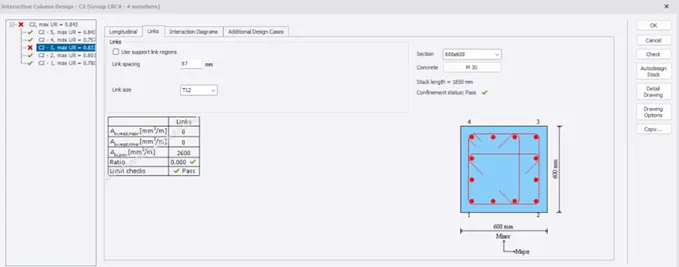
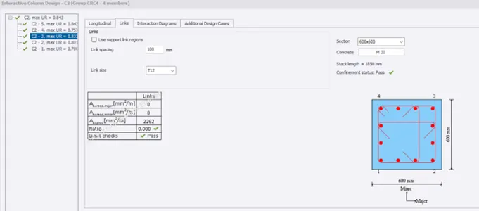
* Right click on any beam – Interactive design
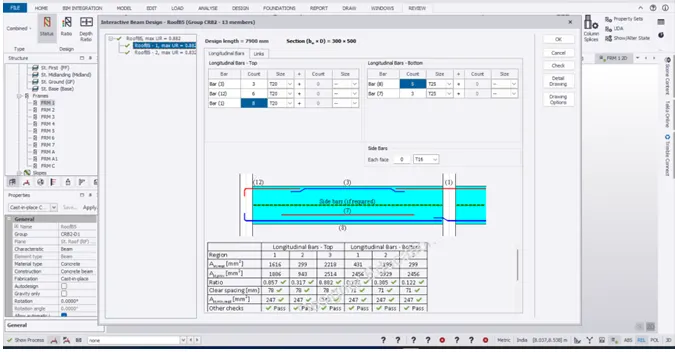
* If you see that a member fails in other checks, click on check
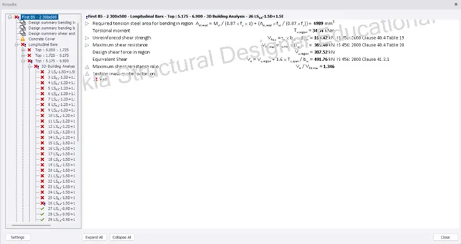
* Notice that the section fails by torsion
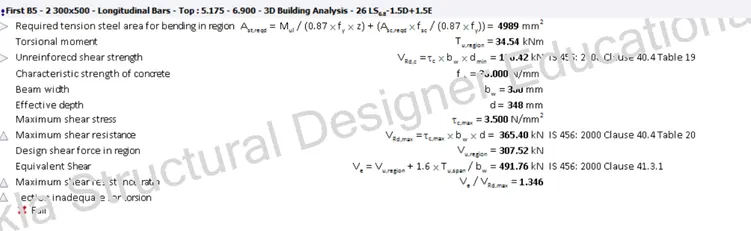
* Notice that by increasing the b and d, the UR can be reduced
* So try increasing the size of members
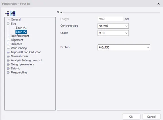
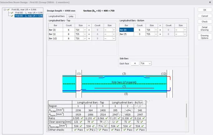
* Now check the member
Foundation design :-
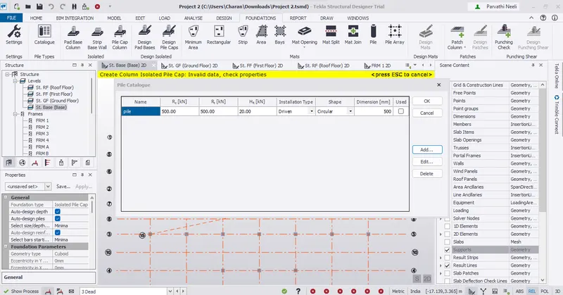
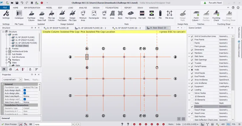
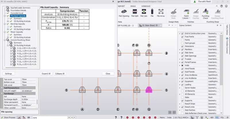
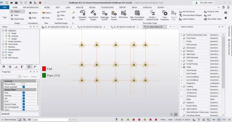
* Go to Base level to design the foundation
* Foundations – Catalogue
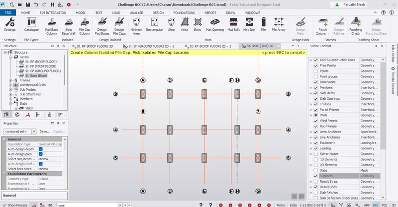
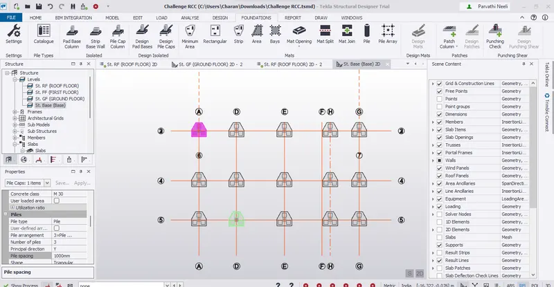
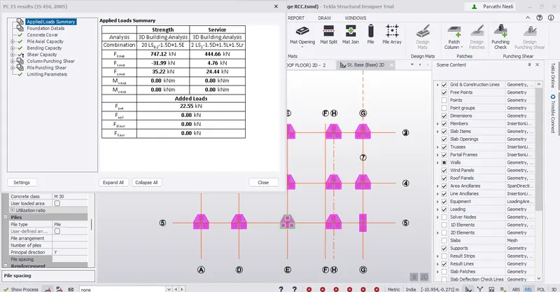
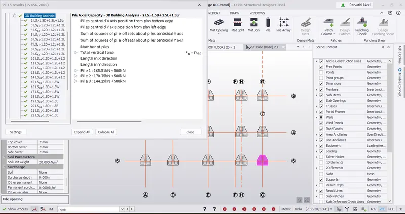
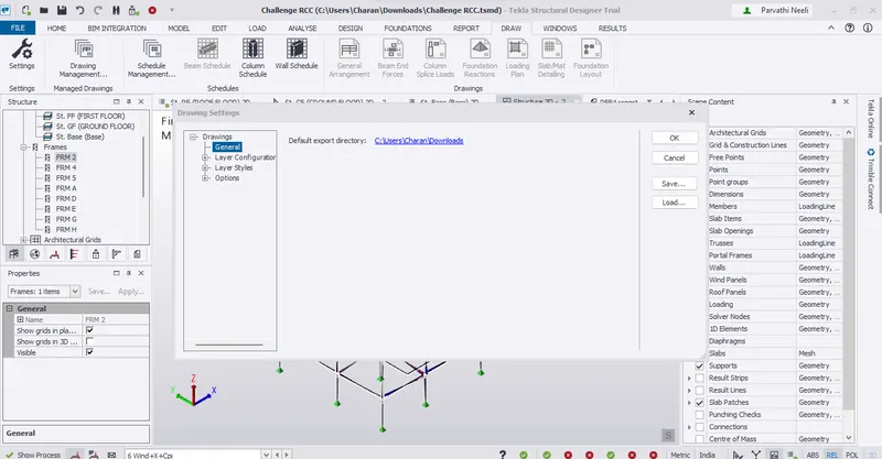
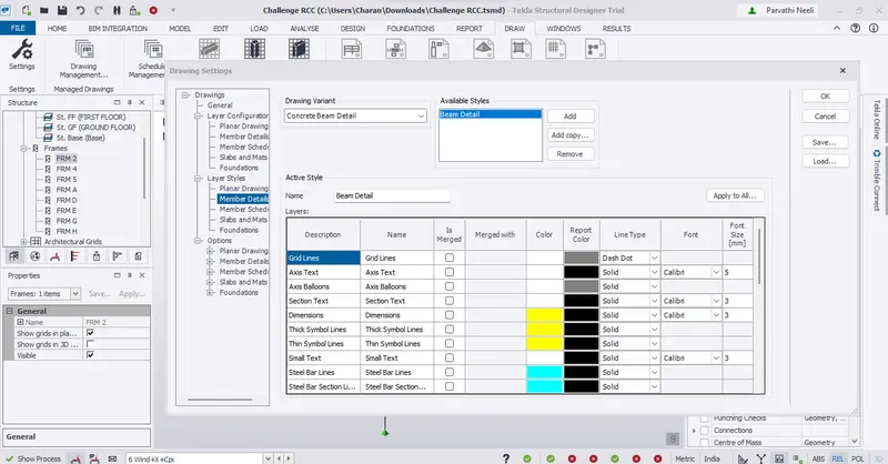
* Go to Draw – Settings
* From the Layer configuration tab, check the available configuration – General Arrangement
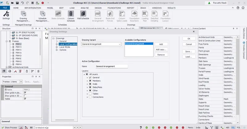
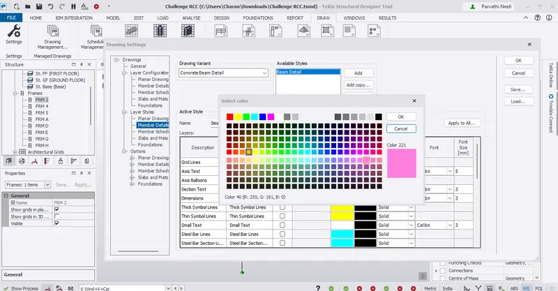
* We can also select the desired colour from the colour palette available
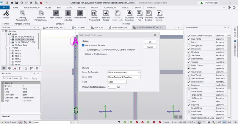
* Go to a particular level and click on General Arrangement
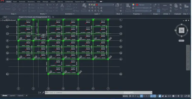
* Now .dxf files get opened in AutoCAD
Result :-
Successfully complete to develop general arrangement for the RC office building. Analyze and design the building as per IS standard code in TEKLA STRUCTURAL DESIGNER. Refer the attached plan and elevation. The building to be designed for dead, live, wind and seismic loading.
Report of each member to be generated and extract drawings for structural plans, beam reinforcement details from the software