Project 2 Adaptive Cruise Control
What is ADAPTIVE CRUISE CONTROL?
Adaptive cruise control (ACC) is a system designed to help vehicles maintain a safe following distance and stay within the speed limit. This system adjusts a car's speed automatically so drivers don't have to.
ACC functions by sensory technology installed within vehicles such as cameras, lasers, and radar equipment, which creates an idea of how close one car is to another, or other objects on the roadway. For this reason, ACC is the basis for future car intelligence.
These sensory technologies allow the car to detect and warn the driver about potential forward collisions. When this happens, red lights begin to flash, and the phrase 'brake now!' appears on the dashboard to help the driver slow down. There might also be an audible warning.
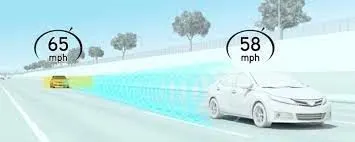
Adaptive Cruise Control
Aim: Developing Adaptive Cruise Control using MATLAB Simulink.
Objective:
1. Need to follow all the process required for model based development like tracebility, taging, Creation of SLDD, Code Generation, Model Advisor Check.
2. Need to use Embedded C coder
3. In Configuration Parameters > Code Generation > Interface > Software Environment > Floating-point Numbers must be enable
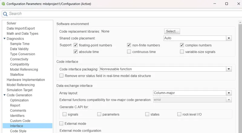
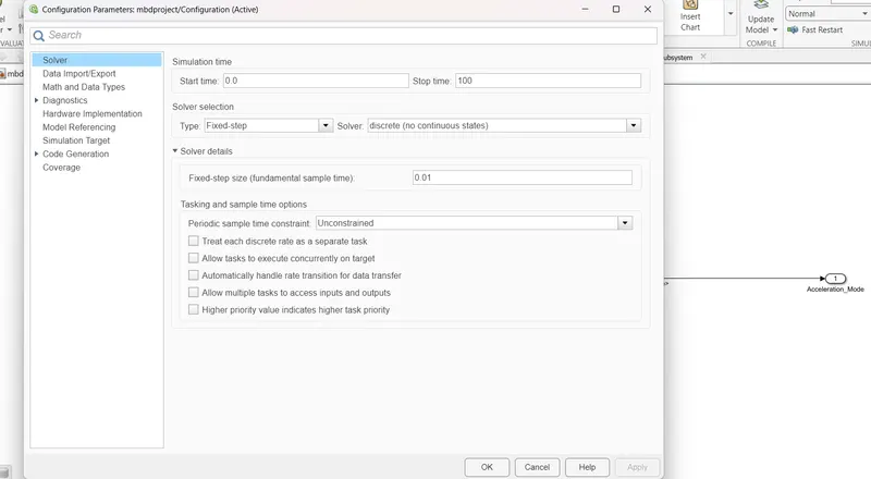
4. Choose Sample Time for all signals as 0.01s.
Steps as follows:
Step1:
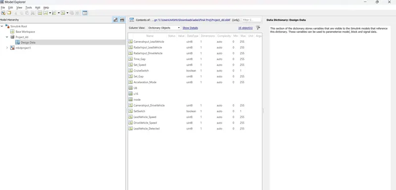
create and save a SLDD file according to given parameters
Signals & Calibration Data List:
|
Signal / Calibration Name |
Signal Type |
Data Type |
Dimension |
Min |
Max |
Initial Value |
Units |
|
CameraInput_LeadVehicle |
Input |
Uint8 |
1 |
0 |
255 |
- |
- |
|
RadarInput_LeadVehicle |
Input |
Uint8 |
1 |
0 |
255 |
- |
- |
|
CameraInput_DriveVehicle |
Input |
Uint8 |
1 |
0 |
255 |
- |
- |
|
RadarInput_DriveVehicle |
Input |
Uint8 |
1 |
0 |
255 |
- |
- |
|
Time_Gap |
Input |
Uint8 |
1 |
0 |
255 |
- |
- |
|
Set_Speed |
Input |
Uint8 |
1 |
0 |
255 |
- |
- |
|
Set_Gap |
Input |
Uint8 |
1 |
0 |
255 |
- |
- |
|
CruiseSwitch |
Input |
Boolean |
1 |
0 |
1 |
- |
- |
|
SetSwitch |
Input |
Boolean |
1 |
0 |
1 |
- |
- |
|
Acceleration_Mode |
Output |
Uint8 |
1 |
0 |
255 |
- |
- |
|
LeadVehicle_Speed |
Output |
Uint8 |
1 |
0 |
255 |
- |
- |
|
DriveVehicle_Speed |
Output |
Uint8 |
1 |
0 |
255 |
- |
- |
|
LeadVehicle_Detected |
Output |
Uint8 |
1 |
0 |
255 |
- |
- |
Step2:
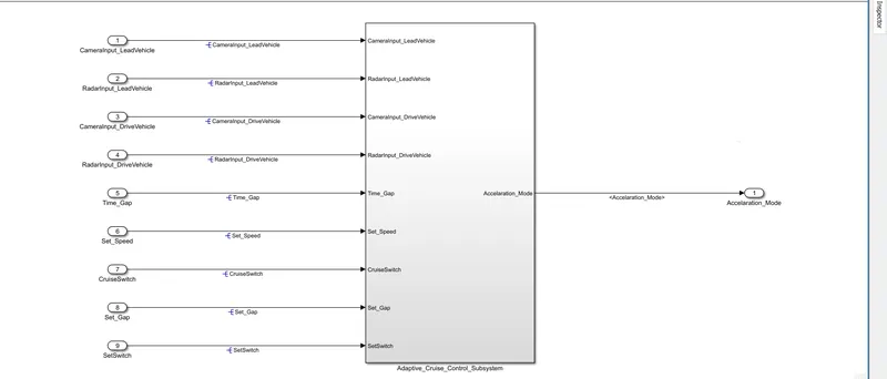
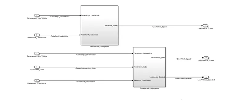
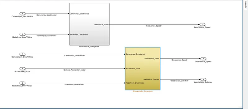
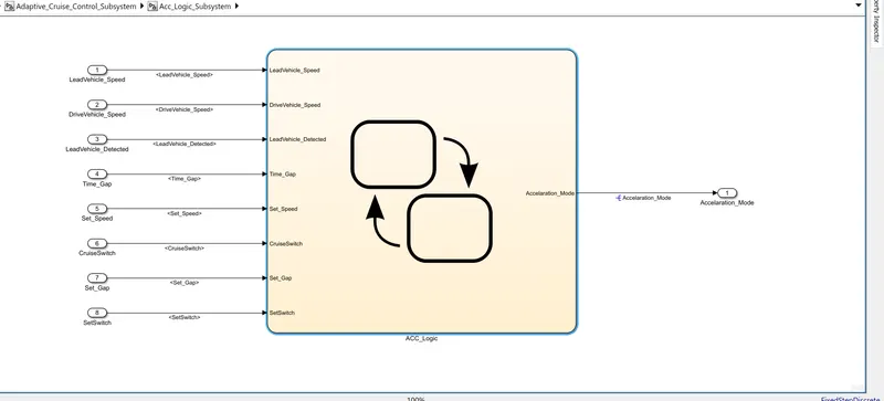
ACC mode subsystem has three necessary more subsystem
Requirement:1 (Lead Vehicle Subsystem)
Requirement:2 (Drive Vehicle Subsystem)
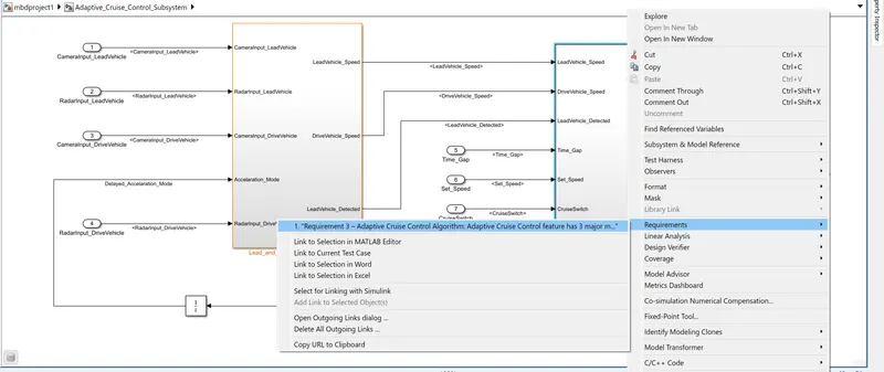
Requirement:3 (Adaptive Cruise Control Subsystem)
Step3:
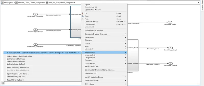
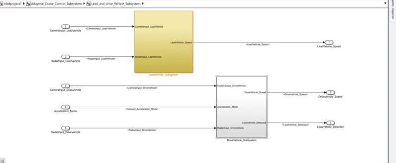
Requirement 1– Lead Vehicle:
- Lead Vehicle is a vehicle which is driving in the road ahead of our drive vehicle. Two input signals (Signal Name: CameraInput_LeadVehicle & RadarInput_LeadVehicle).
- Ideally sensor fusion techniques will be deployed to process & analyze data from camera & radar. For complexity reasons, let’s not adapt to any such algorithms.
- We can simply add both the radar & camera inputs & the corresponding output is read as Speed profile output (Signal Name: LeadVehicle_Speed).
- Speed data of the lead vehicle is critical in implementing the Adaptive Cruise Control algorithm.
Requirement 2 – Drive Vehicle:
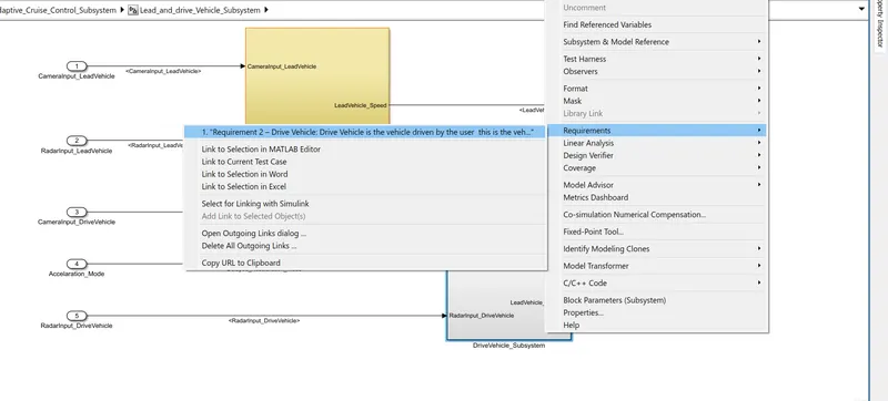
- Drive Vehicle is the vehicle driven by the user & this is the vehicle which has ACC algorithm in it.
- Like the Lead Vehicle, Drive Vehicle algorithm also has 2 input signals (Signal Name: CameraInput_DriveVehicle, RadarInput_DriveVehicle) & one signal coming as an Input to this subsystem (Signal Name: Acceleration_Mode) – three inputs into this requirement in total.
- Like the above requirement, sensor fusion techniques will also be deployed here, for complexity reasons we are ignoring them.
- Two output signals come from this subsystem (Signal Name: DriveVehicle_Speed & LeadVehicle_Detected).
- Signal DriveVehicle_Speed is summation of three input signals mentioned above & LeadVehicle_Detected is renamed from Input Signal RadarInput_DriveVehicle by mere use of Signal Conversion block.
Requirement 3 – Adaptive Cruise Control Algorithm:
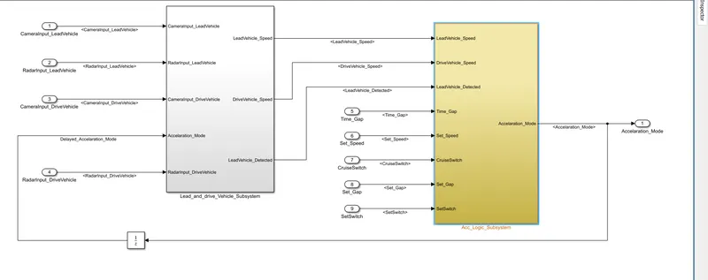
- Adaptive Cruise Control feature has 3 major modes of operation: OFF Mode, STANDBY Mode & ON Mode. This particular requirement has to be implemented as state machine logic in Simulink.
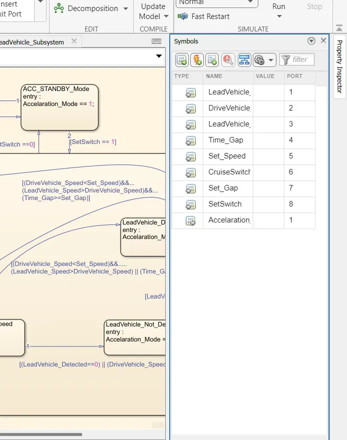
- The input signals to this state machine system are (Signal Name: Time_Gap, Set_Speed, Set_Gap, CruiseSwitch, SetSwitch).
- Also, the output signals (Signal Name: DriveVehicle_Speed & LeadVehicle_Detected) from requirement-2 is fed back as an input signal into this state machine block.
- Additionally, output signal (Signal Name: LeadVehicle_Speed) from requirement-1 is given as an input signal to this state machine block as well.
- Output from this subsystem is a signal (Signal Name: Acceleration_Mode) which governs the vehicular speed of the drive vehicle which automatically adjusts its speed & velocity to match the lead vehicle.
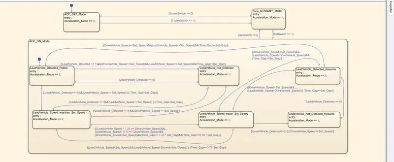
Requirement 3a – ACC OFF MODE state logic:
- This is the default state inside state machine logic. Output signal Acceleration_Mode is at value 0 in this state.
- This state is governed by input signal CruiseSwitch.
- If CruiseSwitch is equal to 1, state ACC STANDBY mode will get activated. If CruiseSwitch is equal to 0, state ACC OFF mode will get activated, from either ACC ON mode or ACC STANDBY mode
Requirement 3b – ACC STANDBY MODE state logic:
- This is the second activated state inside state machine logic. Output signal Acceleration_Mode is at value 1 in this state.
- This state is governed by both input signals CruiseSwitch & SetSwitch.
- If CruiseSwitch is equal to 1, state ACC STANDBY mode will get activated. If CruiseSwitch is equal to 0, state ACC OFF mode will get activated, from either ACC ON mode or ACC STANDBY mode
- If SetSwitch is equal to 1, state ACC ON mode will get activated. If SetSwitch is equal to 0, state ACC STANDBY mode will get activated.
Requirement 3c – ACC ON MODE state logic:
This state will be activated when input signal SetSwitch is equal to 1. There are 6 sub states to this state logic: They are:
- LeadVehicle_Detected_Follow (Default)
- LeadVehicle_Not_Detected
- LeadVehicle_Detected_Resume
- LeadVehicle_Not_Detected_Resume
- LeadVehicle_Speed_lessthan_Set_Speed
- LeadVehicle_Speed_equal_Set_Speed
Requirement 3c (i) – LeadVehicle_Detected_Follow (ACC ON MODE):
- This is the default sub state inside ACC ON MODE state. Output signal Acceleration_Mode is equal to 2.
- Condition to transit from LeadVehicle_Detected_Follow to LeadVehicle_Not_Detected; Input signal condition LeadVehicle_Detected == 0.
- Condition to transit from LeadVehicle_Detected_Follow to LeadVehicle_Speed_lessthan_Set_Speed; Input Signals condition (LeadVehicle_Detected == 1) && (LeadVehicle_Speed < Set_Speed) || (Time_Gap < Set_Gap).
Requirement 3c (ii) – LeadVehicle_Not_Detected (ACC ON MODE):
- Output signal Acceleration_Mode is equal to 1.
- Condition to transit from LeadVehicle_Not_Detected to LeadVehicle_Detected_Follow; Input signals condition [(LeadVehicle_Detected==1) && (DriveVehicle_Speed == Set_Speed) && (LeadVehicle_Speed >= Set_Speed) && (Time_Gap >= Set_Gap)]
- Condition to transit from LeadVehicle_Not_Detected to LeadVehicle_Speed_lessthan_Set_Speed; Input signals condition [(LeadVehicle_Detected == 1) && (LeadVehicle_Speed < Set_Speed) || (Time_Gap < Set_Gap)]
Requirement 3c (iii) – LeadVehicle_Detected_Resume (ACC ON MODE):
- Output signal Acceleration_Mode is equal to 3.
- Condition to transit from LeadVehicle_Detected_Resume to LeadVehicle_Detected_Follow; Input signals condition [(DriveVehicle_Speed == Set_Speed) && (LeadVehicle_Speed >= Set_Speed) && (Time_Gap >= Set_Gap)]
- Condition to transit from LeadVehicle_Detected_Resume to LeadVehicle_Not_Detected_Resume; Input signal condition LeadVehicle_Detected==0.
- Condition to transit from LeadVehicle_Detected_Resume to LeadVehicle_Speed_equal_Set_Speed; Input Signal condition [(DriveVehicle_Speed < Set_Speed) && (LeadVehicle_Speed > DriveVehicle_Speed) && (Time_Gap >= Set_Gap)]
Requirement 3c (iv) - LeadVehicle_Not_Detected_Resume (ACC ON MODE):
- Output signal Acceleration_Mode is equal to 1.
Requirement 3c (v) - LeadVehicle_Speed_lessthan_Set_Speed (ACC ON MODE):
- Output signal Acceleration_Mode is equal to 4.
- Condition to transit from LeadVehicle_Speed_lessthan_Set_Speed to LeadVehicle_Not_Detected; Input signal condition [(LeadVehicle_Detected == 0) && (DriveVehicle_Speed == Set_Speed)]
- Condition to transit from LeadVehicle_Speed_lessthan_Set_Speed to LeadVehicle_Speed_equal_Set_Speed; Input signals condition [((LeadVehicle_Speed*1.25>=DriveVehicle_Speed) && (LeadVehicle_Speed * 0.75<=DriveVehicle_Speed)) && (DriveVehicle_Speed < Set_Speed) && ((Time_Gap<=1.25*Set_Gap) && (Time_Gap >=0.75*Set_Gap))]
Requirement 3c (vi) - LeadVehicle_Speed_equal_Set_Speed (ACC ON MODE):
- Output signal Acceleration_Mode is equal to 5.
- Condition to transit from LeadVehicle_Speed_equal_Set_Speed to LeadVehicle_Not_Detected_Resume; Input signal conditions is [(LeadVehicle_Detected == 0) || (DriveVehicle_Speed <= Set_Speed)]
- Condition to transit from LeadVehicle_Speed_equal_Set_Speed to LeadVehicle_Detected_Resume; Input signal conditions [(DriveVehicle_Speed < Set_Speed) && (LeadVehicle_Speed > DriveVehicle_Speed) || (Time_Gap >= Set_Gap)]
- Condition to transit from LeadVehicle_Speed_equal_Set_Speed to LeadVehicle_Speed_lessthan_Set_Speed; Input signals conditions [(LeadVehicle_Speed<Set_Speed) && (LeadVehicle_Speed<DriveVehicle_Speed) || (Time_Gap == 0.75*Set_Gap)]
Step4:
Symbol pane:
SampleTime:
Step 5
Report:
Step 6
Generate Code:
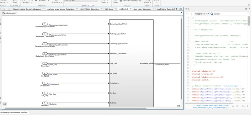
Code:
/*
* Event Support License -- for demonstration use and event support. Not
* for government, research, commercial, or other organizational use.
*
* File: ert_main.c
*
* Code generated for Simulink model 'mbdproject'.
*
* Model version : 3.10
* Simulink Coder version : 9.7 (R2022a) 13-Nov-2021
* C/C++ source code generated on : Tue Feb 7 19:35:30 2023
*
* Target selection: ert.tlc
* Embedded hardware selection: Intel->x86-64 (Windows64)
* Code generation objectives: Unspecified
* Validation result: Not run
*/
#include <stddef.h>
#include <stdio.h> /* This example main program uses printf/fflush */
#include "mbdproject.h" /* Model header file */
/*
* Associating rt_OneStep with a real-time clock or interrupt service routine
* is what makes the generated code "real-time". The function rt_OneStep is
* always associated with the base rate of the model. Subrates are managed
* by the base rate from inside the generated code. Enabling/disabling
* interrupts and floating point context switches are target specific. This
* example code indicates where these should take place relative to executing
* the generated code step function. Overrun behavior should be tailored to
* your application needs. This example simply sets an error status in the
* real-time model and returns from rt_OneStep.
*/
void rt_OneStep(void);
void rt_OneStep(void)
{
static boolean_T OverrunFlag = false;
/* Disable interrupts here */
/* Check for overrun */
if (OverrunFlag) {
rtmSetErrorStatus(mbdproject_M, "Overrun");
return;
}
OverrunFlag = true;
/* Save FPU context here (if necessary) */
/* Re-enable timer or interrupt here */
/* Set model inputs here */
/* Step the model */
mbdproject_step();
/* Get model outputs here */
/* Indicate task complete */
OverrunFlag = false;
/* Disable interrupts here */
/* Restore FPU context here (if necessary) */
/* Enable interrupts here */
}
/*
* The example main function illustrates what is required by your
* application code to initialize, execute, and terminate the generated code.
* Attaching rt_OneStep to a real-time clock is target specific. This example
* illustrates how you do this relative to initializing the model.
*/
int_T main(int_T argc, const char *argv[])
{
/* Unused arguments */
(void)(argc);
(void)(argv);
/* Initialize model */
mbdproject_initialize();
/* Attach rt_OneStep to a timer or interrupt service routine with
* period 0.01 seconds (base rate of the model) here.
* The call syntax for rt_OneStep is
*
* rt_OneStep();
*/
printf("Warning: The simulation will run forever. "
"Generated ERT main won't simulate model step behavior. "
"To change this behavior select the 'MAT-file logging' option.\n");
fflush((NULL));
while (rtmGetErrorStatus(mbdproject_M) == (NULL)) {
/* Perform application tasks here */
}
/* Terminate model */
mbdproject_terminate();
return 0;
}
/*
* File trailer for generated code.
*
* [EOF]
*/
CONCLUSION:
Developed Adaptive Cruise Control feature as per the Requirement Document using MATLAB Simulink
Note:
Requirement tagging file,SLDD file,.c and .h file,Model advisor report were attached below.