Project 2 Adaptive Cruise Control
PROJECT : ADAPTIVE_CRUISE_CONTROL
Before Model Based Development of this project we will understand this by brief theory ;
Lead vehicle
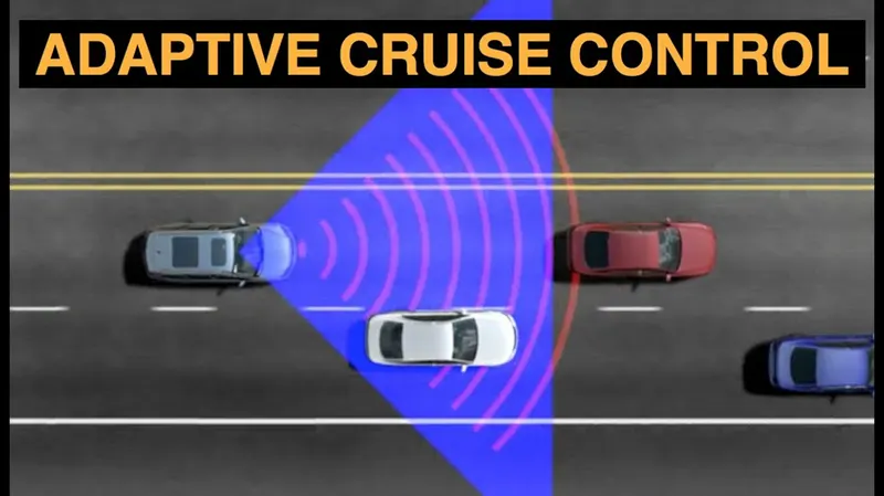
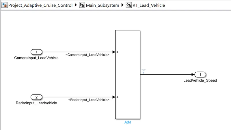
- To detect the lead vehicle speed, simply added both the radar & camera inputs & the corresponding output is read as Speed profile output.
Drive Vehicle
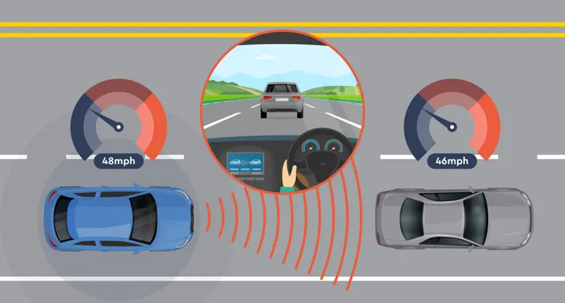
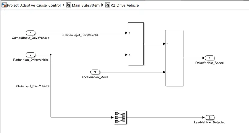
To regulate the "Drive Vehicle speed, as per the Requirement Document added Cameralnput. Radarinput & Acceleration Mode feedback from ACC Algorithm.
- To detect the Lead vehicle. Radarinput is converted using "Signal Conversion Block
- To avoid the algebraic error "Unit delay block is used for the Acceleration Mode feedback.
ACC Algorithm
- Adaptive Cruise Control feature has 3 major modes of operation: OFF Mode. STANDBY Mode & ON Mode. This particular requirement has to be implemented as state machine logic in Simulink
- The input signals to the state machine system are (Signal Name Time Gap. Set Speed Set Gap, CruiseSwitch SetSwitch) Also, the output signals (Signal Name DriveVehicle Speed & LeadVehicle Detected) from requirement-2 is fed back as an input signal into this state machine block
- Additionally, the output signal (Signal Name LeadVehicle Speed) from requirement-1 is given as an input signal to this state machine
- Output from this subsystem a signal (Signal Name Acceleration Model which governs the vehicular speed of the drive vehicle which automatically adjust to speed & velocity to match the lead vehicle.
Now we are Starting Model Development Process ;
First of all, we will make,
Requirement_Analysis_Adaptive_Cruise_Control.docx file...
Then, We shared here Model Development Procedure as per Requirement specifications in Brief;
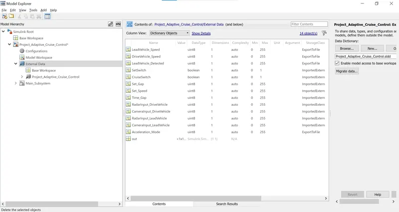
Here we created DATA DICTIONARY(.sldd) file. and which will be helpful for Resolving the Signals.
DATA DICTIONARY(.sldd)
Then, we will Develop the Model.
FINAL DEVELOPED MODEL
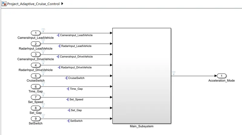
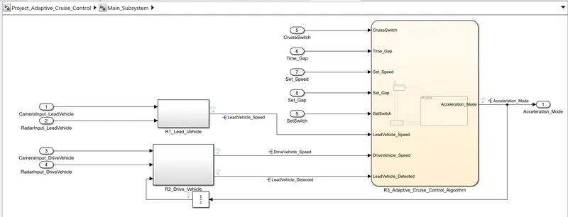
This is our main subsystem.
Inside this Subsystem we have created other subsystems for the Adaptive Cruise Control feature.
INSIDE THE SUBSYSTEM
SUBSYSTEM-1 : REQUIREMENT:1 : R1_Lead_Vehicle
SUBSYSTEM-2 : REQUIREMENT:2 : R2_Drive_Vehicle
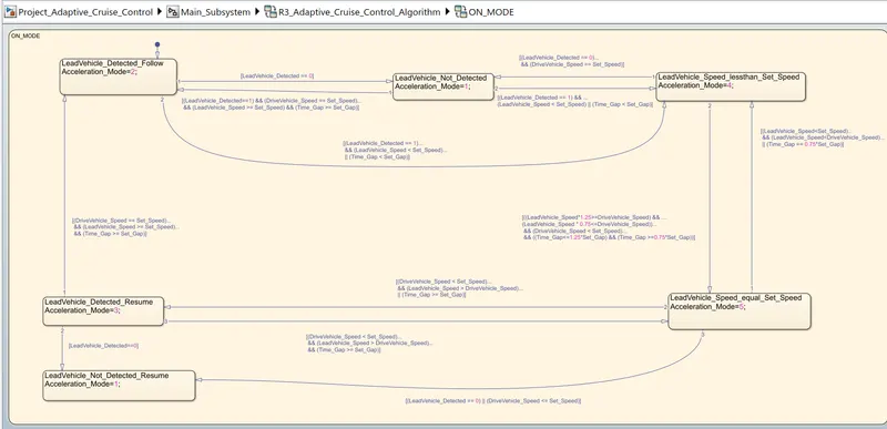
SUBSYSTEM-2 as StateFlow Chart : REQUIREMENT:3 : R3_Adaptive_Cruise_Control_Algorithm
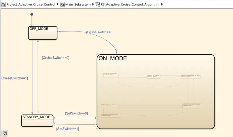
and we have created subcharts and given conditions as per Requirement Analysis as below.
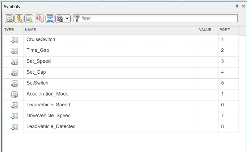
This is the Symbols Pane for identifying all the Inputs and Outputs in the Stateflow chart.
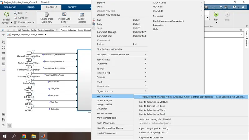
as per below, Requirement Tagging & Tracability completed. for all subsystems.
here we attached one main snapshot for reference.
After Running the model Successfully,
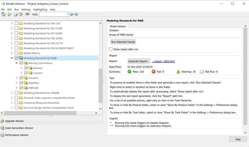
We are Running The MODEL ADVISOR.
and we have created changes to the model as per Recommanded actions.
and Results as per below :
After that Code Generation done via Embedded Coder Successfully.
and it will be flashing in the ECU Unit of Vehicle.....

Files as below ;
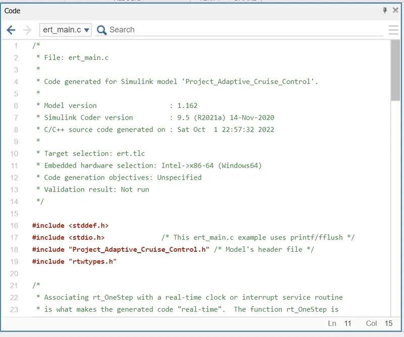
1) ert_main.c
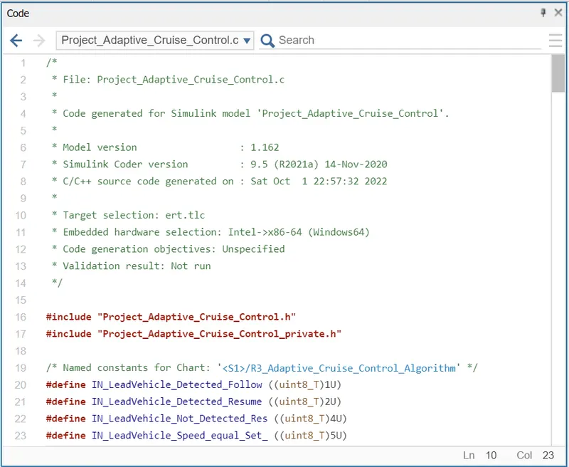
2)Project_Adaptive_Cruise_Control.c
Results:
After implementing the ACC model run the simulation. So the model is running successfully without any errors then the Adaptive Cruise Control works as per the requirement
The model is running successfully without any error.
Conclusion:
Hence. The Adaptive Cruise Control feature is developed as per the Requirement Document using MATLAB Simulink.
........................THANK.....YOU...........................