Project 2 Adaptive Cruise Control
AIM: Developing Adaptive Cruise Control feature as per the Requirement Document using MATLAB Simulink.
SLDD CREATION:
The Data Dictionary containing the Calibration and Signals is developed as shown below:
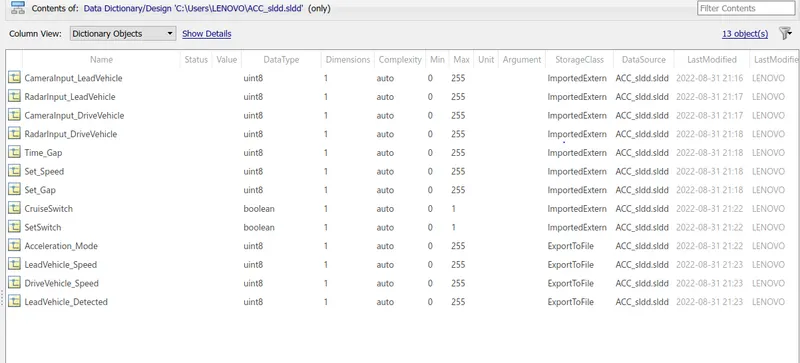
The other parameters like signal dimensions,min, max values, initial values of all the signals have been set as shown below:

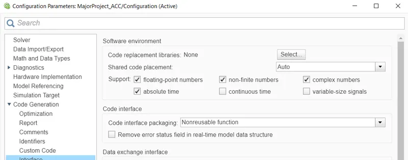
The required Code generation settings have been altered as shown below:
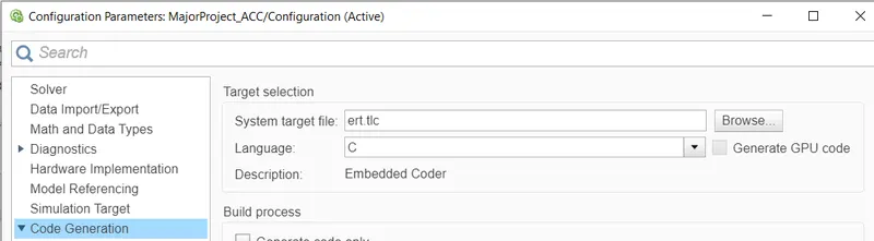
Also the Code generation type is selected in "Embedded Coder" mode as shown below:
Requirement 1: LEAD VEHICLE:
As mentioned in the requirement, the radar and camera inputs are simply added to give the speed output as shown in the figure below:
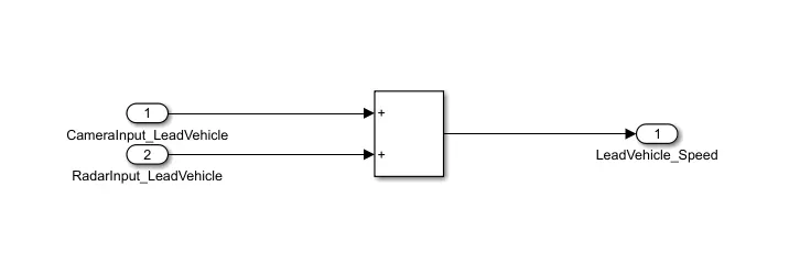
The Subsystem related to this requirement is as shown below, the output has been connected to a Goto block so that it can be used in the ACC algorithm without any signal routing.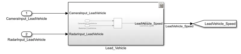
Requirement 2 – Drive Vehicle:
The Drive Vehicle subsystem is as shown below: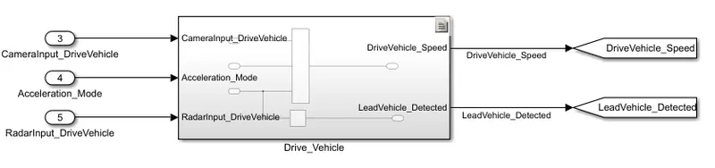
The logic inside the subsystem is implemented as stated in the requirement.
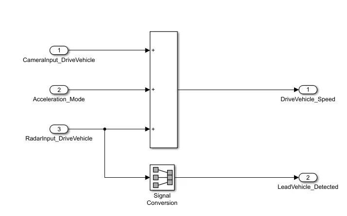
As shown above signal DriveVehicle_Speed is taken by adding the three given inputs and and the signal LeadVehicle_Speed is obtained using Signal Conversion block.
Again Goto blocks have been attached to the output signals to use them as inputs to the Adaptive Cruise Control algorithm.
Requirement 3 – Adaptive Cruise Control Algorithm:
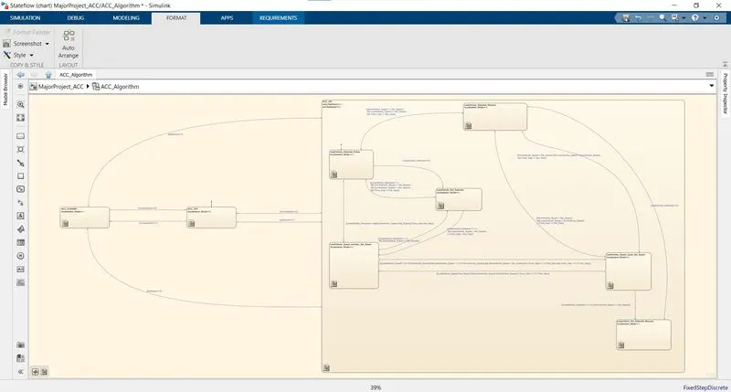
This requirement has been implemented using the Stateflow logic in chart block of Simulink as shown below:
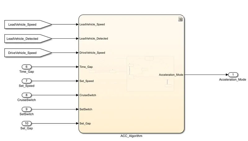
Among the 8 inputs of the chart shown above, the first 3 are deribbed from the previous requirements and the remaining are externally applied.The three states of ACC algorithm namely- OFF, ON and STANDBY have been implemented using the 3 states of chart.
Also, the sub-states of the STANDBY MODE havce been further implemented using 6 different states inside the STANDBY state.
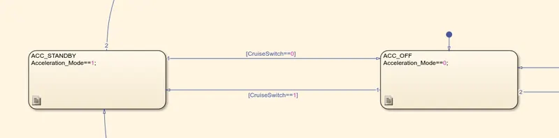
STATES FOR ACC OFF and STANDBY MODE:
STATES FOR ACC ON MODE:

The Complete interconnected state diagram of ACC algorithm is shown in the figure below:
Requirement 3a – ACC OFF MODE state logic:

As can be seen from the figure above, the ACC_OFF mode can be activated either from STANDBY or ACC_ON mode by enabling the input condition "CruiseSwitch=0".
This mode sets the "acceleration mode =0" and is the default state in the algorithm.
Requirement 3b – ACC STANDBY MODE state logic:
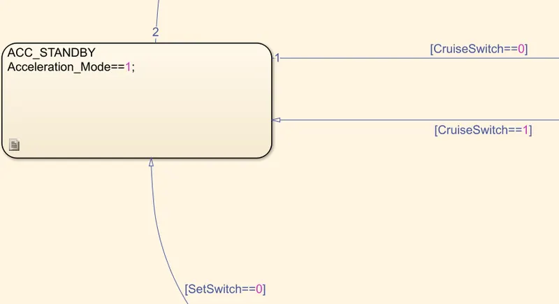
As can be seen from the above image, the STANDBY mode depends on both the inputs "CruiseSwitch" and "SetSwitch".
It can be activated if "CruiseSwitch=1" or "SetSwitch=0".
This mode sets the Acceleration Mode as 1.It can be attained from OFF mode when "CruiseSwitch=1" and from ON mode when "SetSwitch=0".
Requirement 3c – ACC ON MODE state logic:
This state will be activated when input signal SetSwitch is equal to 1. There are 6 sub states to this state logic: They are:
- LeadVehicle_Detected_Follow (Default)
- LeadVehicle_Not_Detected
- LeadVehicle_Detected_Resume
- LeadVehicle_Not_Detected_Resume
- LeadVehicle_Speed_lessthan_Set_Speed
- LeadVehicle_Speed_equal_Set_Speed
This mode can be attained from the OFF or STANDBY mode if "SetSwitch=1". All the 6 substates required to be implemented have been shown in the figure below:
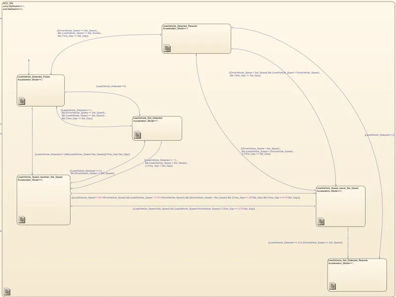
The complete implementation for each of the sub-states in the ACC ON mode can be viewed in the actual model file "MajorProject_ACC".
CODE GENERATION:
As mentioned in the requirement the coder used for Code generation is "Embedded Coder" and the Code generated is stored in the file :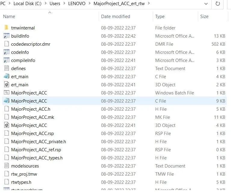
Some screenshots of the source code generated are shown below:
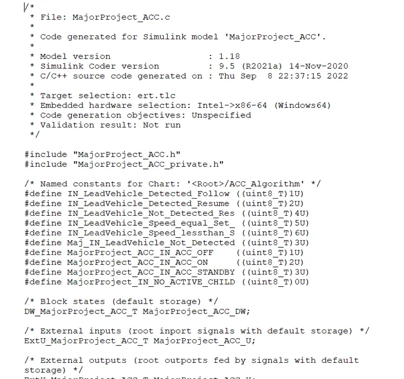
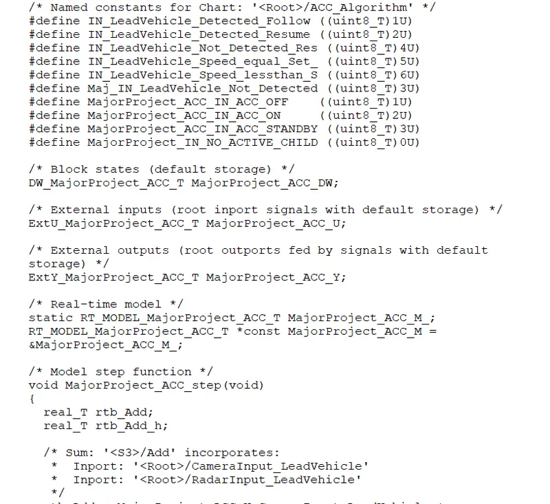
The file also has been attached at the end of the solution.
REQUIREMENT TAGGING:
The procedure for the requirenment linking is as given below:
- Copy all the given statements of the requirements given in a Word document.
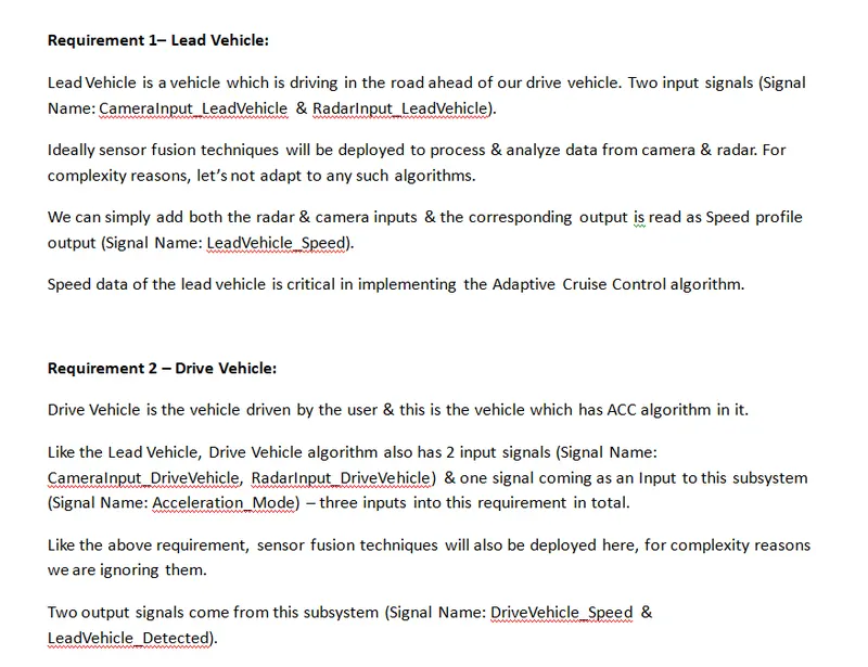
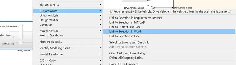
- Select the particular requirement in the document to be tagged and "Right Click Simulink block-->Go to Requirements-->Link to selection in Word".
- Once a particular requirement is linked, the correspoding block will show a documnet icon as shown below:
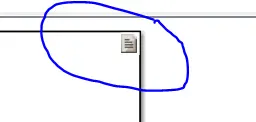
This ensures the requirement has been linked.
MODEL ADVISOR CHECK:
The procedure for the Model Advisor Check is as given below:
- Goto Modelling-->Model Advisor-->Select the Model name-->Modeling standards for MAB
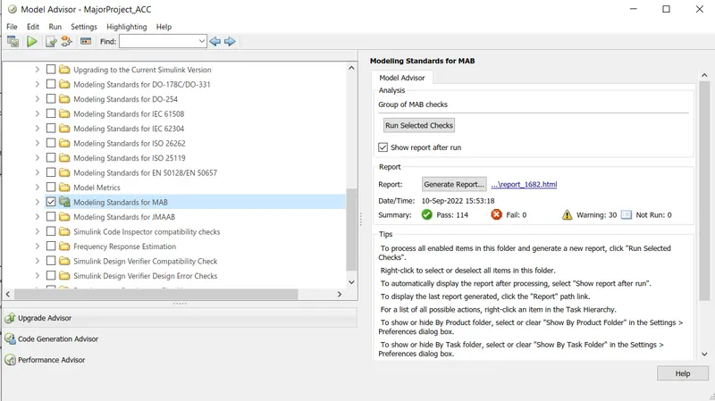
- Check the "Show report after run" and click on "Run Selected Checks".