Project 2 Adaptive Cruise Control
Aim Of The Challange :
Adaptive cruise control (ACC) is an available cruise control advanced driver-assistance system for road vehicles that automatically adjusts the vehicle speed to maintain a safe distance from vehicles ahead. As of 2019, it is also called by 20 unique names that describe that basic functionality. This is also known as Dynamic cruise control
Control is based on sensor information from on-board sensors. Such systems may use a radar or laser sensor or a camera setup allowing the vehicle to brake when it detects the car is approaching another vehicle ahead, then accelerate when traffic allows it to.
ACC technology is regarded as a key component of future generations of intelligent cars. The technology enhances passenger safety and convenience as well as increasing road capacity by maintaining optimal separation between vehicles and reducing driver errors. Vehicles with autonomous cruise control are considered a Level 1 autonomous car, as defined by SAE International. When combined with another driver assist feature such as lane centering, the vehicle is considered a Level 2 autonomous car.
Types of Adaptive Cruise Control
Radar-Based Systems
According to eInfoChips, radar-based systems work by placing radar-based sensors on or around plastic fascias to detect your vehicle's surroundings. Each radar sensor works together to create a comprehensive picture of the vehicle's proximity to other cars or potentially hazardous objects. This type of sensor can look different depending on the design and model of the car.
Laser-Based Systems
As mentioned by Electronic Design, this type of ACC system operates out of a large black box typically placed in the grille of your vehicle. It uses laser technology to detect the proximity of objects to your car. It does not operate well during rainstorms and other weather conditions.
Binocular Computer Vision Systems (Optical)
According to ExtremeTech, this is a relatively new ACC system put into use in 2013. It uses small cameras that are placed on the back of a vehicle's rearview mirror to detect front-facing objects.
Assisting Systems
Assisting systems are radar-based add-ons that customers can buy together. These pre-crash systems can offer lane control, brake assistance, cruise control, proximity alerts to objects like corners, and steering power.
Multi-Sensor Systems
According to Fierce Electronics, adaptive cruise control systems sometimes integrate more than one type of sensor to aid in a vehicle's operation. Multi-sensor systems incorporate several different sensor types to provide a driver with advanced information. These sensors might include GPS data equipment or cameras to gather information about a vehicle's geographic environment and proximity to other cars.
Predictive Systems
As mentioned by Autoblog, prediction systems are a type of ACC that uses sensory data to predict the actions of neighboring vehicles. This means that your car might slow down to brace for another vehicle suddenly switching lanes and, in doing so, promotes passenger safety.
Adaptive cruise control is evolving each year. Car companies are continuously making adjustments to this technology and, in doing so, creating more common and affordable options that can be purchased with a new car or added to older car models, making driving safer for everyday people.
Objective of Main Project:
- Developing Adaptive Cruise Control feature as per the Requirement Document using MATLAB Simulink.
- Follow all the MBD related processes: Requirement Tagging & Traceability, SLDD creation, Configuration Parameter changes, Model Advisor check & Code Generation.
- In Configuration Parameters: enable “Support Floating Numbers” under Code Generation settings.
- Use Embedded Coder to generate the code.
- If choosing code generation, Storage class for Input signals: ImportedExtern; Storage class for Output signal: Export to File; Storage class for local signals: localizable; Storage class for calibration signals: Const.
- Choose sample time for all signals as 0.01s
Requirement 1– Lead Vehicle:
- Lead Vehicle is a vehicle which is driving in the road ahead of our drive vehicle. Two input signals (Signal Name: CameraInput_LeadVehicle & RadarInput_LeadVehicle).
- Ideally sensor fusion techniques will be deployed to process & analyze data from camera & radar. For complexity reasons, let’s not adapt to any such algorithms.
- We can simply add both the radar & camera inputs & the corresponding output is read as Speed profile output (Signal Name: LeadVehicle_Speed).
- Speed data of the lead vehicle is critical in implementing the Adaptive Cruise Control algorithm.
Requirement 2 – Drive Vehicle:
- Drive Vehicle is the vehicle driven by the user & this is the vehicle which has ACC algorithm in it.
- Like the Lead Vehicle, Drive Vehicle algorithm also has 2 input signals (Signal Name: CameraInput_DriveVehicle, RadarInput_DriveVehicle) & one signal coming as an Input to this subsystem (Signal Name: Acceleration_Mode) – three inputs into this requirement in total.
- Like the above requirement, sensor fusion techniques will also be deployed here, for complexity reasons we are ignoring them.
- Two output signals come from this subsystem (Signal Name: DriveVehicle_Speed & LeadVehicle_Detected).
- Signal DriveVehicle_Speed is summation of three input signals mentioned above & LeadVehicle_Detected is renamed from Input Signal RadarInput_DriveVehicle by mere use of Signal Conversion block.
Requirement 3 – Adaptive Cruise Control Algorithm:
- Adaptive Cruise Control feature has 3 major modes of operation: OFF Mode, STANDBY Mode & ON Mode. This particular requirement has to be implemented as state machine logic in Simulink.
- The input signals to this state machine system are (Signal Name: Time_Gap, Set_Speed, Set_Gap, CruiseSwitch, SetSwitch).
- Also, the output signals (Signal Name: DriveVehicle_Speed & LeadVehicle_Detected) from requirement-2 is fed back as an input signal into this state machine block.
- Additionally, output signal (Signal Name: LeadVehicle_Speed) from requirement-1 is given as an input signal to this state machine block as well.
- Output from this subsystem is a signal (Signal Name: Acceleration_Mode) which governs the vehicular speed of the drive vehicle which automatically adjusts its speed & velocity to match the lead vehicle.
Requirement 3a – ACC OFF MODE state logic:
- This is the default state inside state machine logic. Output signal Acceleration_Mode is at value 0 in this state.
- This state is governed by input signal CruiseSwitch.
- If CruiseSwitch is equal to 1, state ACC STANDBY mode will get activated. If CruiseSwitch is equal to 0, state ACC OFF mode will get activated, from either ACC ON mode or ACC STANDBY mode
Requirement 3b – ACC STANDBY MODE state logic:
- This is the second activated state inside state machine logic. Output signal Acceleration_Mode is at value 1 in this state.
- This state is governed by both input signals CruiseSwitch & SetSwitch.
- If CruiseSwitch is equal to 1, state ACC STANDBY mode will get activated. If CruiseSwitch is equal to 0, state ACC OFF mode will get activated, from either ACC ON mode or ACC STANDBY mode
- If SetSwitch is equal to 1, state ACC ON mode will get activated. If SetSwitch is equal to 0, state ACC STANDBY mode will get activated.
Requirement 3c – ACC ON MODE state logic:
This state will be activated when input signal SetSwitch is equal to 1. There are 6 sub states to this state logic: They are:
- LeadVehicle_Detected_Follow (Default)
- LeadVehicle_Not_Detected
- LeadVehicle_Detected_Resume
- LeadVehicle_Not_Detected_Resume
- LeadVehicle_Speed_lessthan_Set_Speed
- LeadVehicle_Speed_equal_Set_Speed
Requirement 3c (i) – LeadVehicle_Detected_Follow (ACC ON MODE):
- This is the default sub state inside ACC ON MODE state. Output signal Acceleration_Mode is equal to 2.
- Condition to transit from LeadVehicle_Detected_Follow to LeadVehicle_Not_Detected; Input signal condition LeadVehicle_Detected == 0.
- Condition to transit from LeadVehicle_Detected_Follow to LeadVehicle_Speed_lessthan_Set_Speed; Input Signals condition (LeadVehicle_Detected == 1) && (LeadVehicle_Speed < Set_Speed) || (Time_Gap < Set_Gap).
Requirement 3c (ii) – LeadVehicle_Not_Detected (ACC ON MODE):
- Output signal Acceleration_Mode is equal to 1.
- Condition to transit from LeadVehicle_Not_Detected to LeadVehicle_Detected_Follow; Input signals condition [(LeadVehicle_Detected==1) && (DriveVehicle_Speed == Set_Speed) && (LeadVehicle_Speed >= Set_Speed) && (Time_Gap >= Set_Gap)]
- Condition to transit from LeadVehicle_Not_Detected to LeadVehicle_Speed_lessthan_Set_Speed; Input signals condition [(LeadVehicle_Detected == 1) && (LeadVehicle_Speed < Set_Speed) || (Time_Gap < Set_Gap)]
Requirement 3c (iii) – LeadVehicle_Detected_Resume (ACC ON MODE):
- Output signal Acceleration_Mode is equal to 3.
- Condition to transit from LeadVehicle_Detected_Resume to LeadVehicle_Detected_Follow; Input signals condition [(DriveVehicle_Speed == Set_Speed) && (LeadVehicle_Speed >= Set_Speed) && (Time_Gap >= Set_Gap)]
- Condition to transit from LeadVehicle_Detected_Resume to LeadVehicle_Not_Detected_Resume; Input signal condition LeadVehicle_Detected==0.
- Condition to transit from LeadVehicle_Detected_Resume to LeadVehicle_Speed_equal_Set_Speed; Input Signal condition [(DriveVehicle_Speed < Set_Speed) && (LeadVehicle_Speed > DriveVehicle_Speed) && (Time_Gap >= Set_Gap)]
Requirement 3c (iv) - LeadVehicle_Not_Detected_Resume (ACC ON MODE):
- Output signal Acceleration_Mode is equal to 1.
Requirement 3c (v) - LeadVehicle_Speed_lessthan_Set_Speed (ACC ON MODE):
- Output signal Acceleration_Mode is equal to 4.
- Condition to transit from LeadVehicle_Speed_lessthan_Set_Speed to LeadVehicle_Not_Detected; Input signal condition [(LeadVehicle_Detected == 0) && (DriveVehicle_Speed == Set_Speed)]
- Condition to transit from LeadVehicle_Speed_lessthan_Set_Speed to LeadVehicle_Speed_equal_Set_Speed; Input signals condition [((LeadVehicle_Speed*1.25>=DriveVehicle_Speed) && (LeadVehicle_Speed * 0.75<=DriveVehicle_Speed)) && (DriveVehicle_Speed < Set_Speed) && ((Time_Gap<=1.25*Set_Gap) && (Time_Gap >=0.75*Set_Gap))]
Requirement 3c (vi) - LeadVehicle_Speed_equal_Set_Speed (ACC ON MODE):
- Output signal Acceleration_Mode is equal to 5.
- Condition to transit from LeadVehicle_Speed_equal_Set_Speed to LeadVehicle_Not_Detected_Resume; Input signal conditions is [(LeadVehicle_Detected == 0) || (DriveVehicle_Speed <= Set_Speed)]
- Condition to transit from LeadVehicle_Speed_equal_Set_Speed to LeadVehicle_Detected_Resume; Input signal conditions [(DriveVehicle_Speed < Set_Speed) && (LeadVehicle_Speed > DriveVehicle_Speed) || (Time_Gap >= Set_Gap)]
- Condition to transit from LeadVehicle_Speed_equal_Set_Speed to LeadVehicle_Speed_lessthan_Set_Speed; Input signals conditions [(LeadVehicle_Speed
First we have to create a simulink data dicitionary file in the format of SLDD file.
SLDD FILE CREATION:
The Sldd data files are related to the Matalb and simulink simulations.The sldd file stores the data it like matalab workspace.
- To create a SLDD file open the simulink blank model and go to modelling properties.
- Then select link to data dicitionary option to create a sldd file.
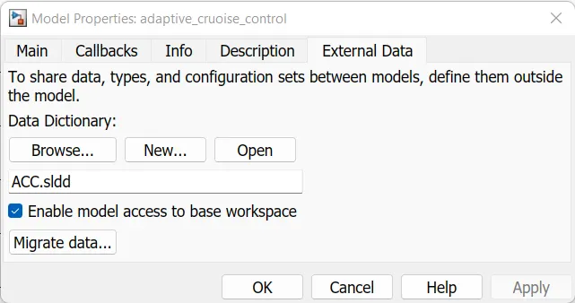
- we have to create a Simulink parameters signals . so that we have to select the model properties select external data to create a new SLDD FILE . In that we are selecting the design data to create a sldd data.
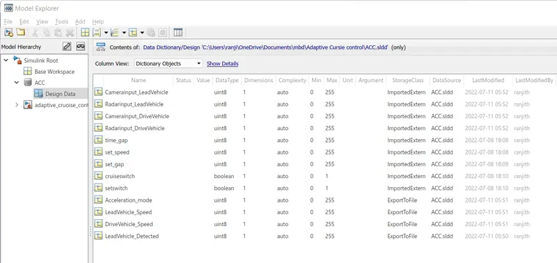
After creating the sldd data we have to save the sldd file in the form of ACC.sldd file
MODELING:
Over all Simulink model of the Adaptive Cruise Control.
First we are creating a new subsystem and named as Adaptive cruise control.
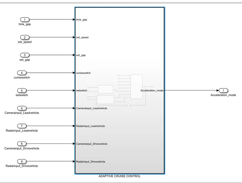
As per our challange now we are going to create some subsytems and stateflow chart for the function of adaptive cruise control in the car.
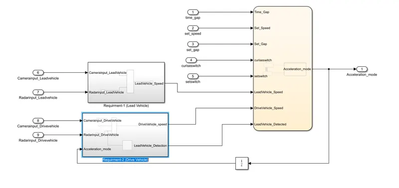
Then double click the subsystem to create a two new substems and one stateflow chart as per the requiorments.
- The two subsystems are named as a Requirment-1 (Lead Vehicle) & Requirment-2 (Drive Vehicle).
- The input and outputs are according to the the given data created.
- Now we are going to create simulink model for the each subsystems as per our requirments.
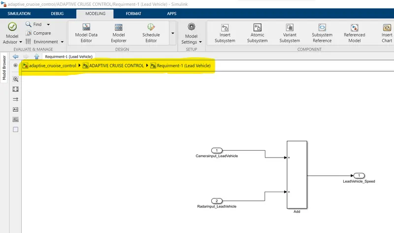
Requirement 1– Lead Vehicle:
- Lead Vehicle is a vehicle which is driving in the road ahead of our drive vehicle. Two input signals (Signal Name: CameraInput_LeadVehicle & RadarInput_LeadVehicle).
- Ideally sensor fusion techniques will be deployed to process & analyze data from camera & radar. For complexity reasons, let’s not adapt to any such algorithms.
- We can simply add both the radar & camera inputs & the corresponding output is read as Speed profile output (Signal Name: LeadVehicle_Speed).
- Speed data of the lead vehicle is critical in implementing the Adaptive Cruise Control algorithm.
Requirement 2 – Drive Vehicle:
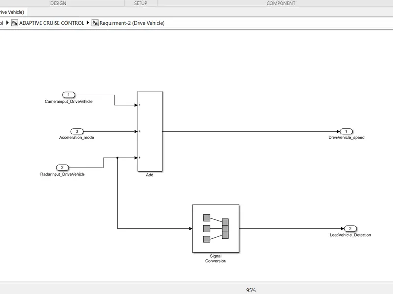
- Drive Vehicle is the vehicle driven by the user & this is the vehicle which has ACC algorithm in it.
- Like the Lead Vehicle, Drive Vehicle algorithm also has 2 input signals (Signal Name: CameraInput_DriveVehicle, RadarInput_DriveVehicle) & one signal coming as an Input to this subsystem (Signal Name: Acceleration_Mode) – three inputs into this requirement in total.
- Like the above requirement, sensor fusion techniques will also be deployed here, for complexity reasons we are ignoring them.
- Two output signals come from this subsystem (Signal Name: DriveVehicle_Speed & LeadVehicle_Detected).
- Signal DriveVehicle_Speed is summation of three input signals mentioned above & LeadVehicle_Detected is renamed from Input Signal RadarInput_DriveVehicle by mere use of Signal Conversion block.
Requirement 3 – Adaptive Cruise Control Algorithm:
- Adaptive Cruise Control feature has 3 major modes of operation: OFF Mode, STANDBY Mode & ON Mode. This particular requirement has to be implemented as state machine logic in Simulink.
- The input signals to this state machine system are (Signal Name: Time_Gap, Set_Speed, Set_Gap, CruiseSwitch, SetSwitch).
- Also, the output signals (Signal Name: DriveVehicle_Speed & LeadVehicle_Detected) from requirement-2 is fed back as an input signal into this state machine block.
- Additionally, output signal (Signal Name: LeadVehicle_Speed) from requirement-1 is given as an input signal to this state machine block as well.
- Output from this subsystem is a signal (Signal Name: Acceleration_Mode) which governs the vehicular speed of the drive vehicle which automatically adjusts its speed & velocity to match the lead vehicle.
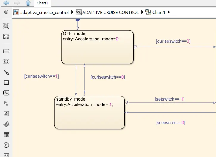
Requirement 3a – ACC OFF MODE state logic:
- This is the default state inside state machine logic. Output signal Acceleration_Mode is at value 0 in this state.
- This state is governed by input signal CruiseSwitch.
- If CruiseSwitch is equal to 1, state ACC STANDBY mode will get activated. If CruiseSwitch is equal to 0, state ACC OFF mode will get activated, from either ACC ON mode or ACC STANDBY mode
Requirement 3b – ACC STANDBY MODE state logic:
- This is the second activated state inside state machine logic. Output signal Acceleration_Mode is at value 1 in this state.
- This state is governed by both input signals CruiseSwitch & SetSwitch.
- If CruiseSwitch is equal to 1, state ACC STANDBY mode will get activated. If CruiseSwitch is equal to 0, state ACC OFF mode will get activated, from either ACC ON mode or ACC STANDBY mode
- If SetSwitch is equal to 1, state ACC ON mode will get activated. If SetSwitch is equal to 0, state ACC STANDBY mode will get activated.
Requirement 3c – ACC ON MODE state logic:
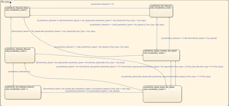
This state will be activated when input signal SetSwitch is equal to 1. There are 6 sub states to this state logic: They are:
- LeadVehicle_Detected_Follow (Default)
- LeadVehicle_Not_Detected
- LeadVehicle_Detected_Resume
- LeadVehicle_Not_Detected_Resume
- LeadVehicle_Speed_lessthan_Set_Speed
- LeadVehicle_Speed_equal_Set_Speed
Requirement 3c (i) – LeadVehicle_Detected_Follow (ACC ON MODE):
- This is the default sub state inside ACC ON MODE state. Output signal Acceleration_Mode is equal to 2.
- Condition to transit from LeadVehicle_Detected_Follow to LeadVehicle_Not_Detected; Input signal condition LeadVehicle_Detected == 0.
- Condition to transit from LeadVehicle_Detected_Follow to LeadVehicle_Speed_lessthan_Set_Speed; Input Signals condition (LeadVehicle_Detected == 1) && (LeadVehicle_Speed < Set_Speed) || (Time_Gap < Set_Gap).
Requirement 3c (ii) – LeadVehicle_Not_Detected (ACC ON MODE):
- Output signal Acceleration_Mode is equal to 1.
- Condition to transit from LeadVehicle_Not_Detected to LeadVehicle_Detected_Follow; Input signals condition [(LeadVehicle_Detected==1) && (DriveVehicle_Speed == Set_Speed) && (LeadVehicle_Speed >= Set_Speed) && (Time_Gap >= Set_Gap)]
- Condition to transit from LeadVehicle_Not_Detected to LeadVehicle_Speed_lessthan_Set_Speed; Input signals condition [(LeadVehicle_Detected == 1) && (LeadVehicle_Speed < Set_Speed) || (Time_Gap < Set_Gap)]
Requirement 3c (iii) – LeadVehicle_Detected_Resume (ACC ON MODE):
- Output signal Acceleration_Mode is equal to 3.
- Condition to transit from LeadVehicle_Detected_Resume to LeadVehicle_Detected_Follow; Input signals condition [(DriveVehicle_Speed == Set_Speed) && (LeadVehicle_Speed >= Set_Speed) && (Time_Gap >= Set_Gap)]
- Condition to transit from LeadVehicle_Detected_Resume to LeadVehicle_Not_Detected_Resume; Input signal condition LeadVehicle_Detected==0.
- Condition to transit from LeadVehicle_Detected_Resume to LeadVehicle_Speed_equal_Set_Speed; Input Signal condition [(DriveVehicle_Speed < Set_Speed) && (LeadVehicle_Speed > DriveVehicle_Speed) && (Time_Gap >= Set_Gap)]
Requirement 3c (iv) - LeadVehicle_Not_Detected_Resume (ACC ON MODE):
- Output signal Acceleration_Mode is equal to 1.
Requirement 3c (v) - LeadVehicle_Speed_lessthan_Set_Speed (ACC ON MODE):
- Output signal Acceleration_Mode is equal to 4.
- Condition to transit from LeadVehicle_Speed_lessthan_Set_Speed to LeadVehicle_Not_Detected; Input signal condition [(LeadVehicle_Detected == 0) && (DriveVehicle_Speed == Set_Speed)]
- Condition to transit from LeadVehicle_Speed_lessthan_Set_Speed to LeadVehicle_Speed_equal_Set_Speed; Input signals condition [((LeadVehicle_Speed*1.25>=DriveVehicle_Speed) && (LeadVehicle_Speed * 0.75<=DriveVehicle_Speed)) && (DriveVehicle_Speed < Set_Speed) && ((Time_Gap<=1.25*Set_Gap) && (Time_Gap >=0.75*Set_Gap))]
Requirement 3c (vi) - LeadVehicle_Speed_equal_Set_Speed (ACC ON MODE):
- Output signal Acceleration_Mode is equal to 5.
- Condition to transit from LeadVehicle_Speed_equal_Set_Speed to LeadVehicle_Not_Detected_Resume; Input signal conditions is [(LeadVehicle_Detected == 0) || (DriveVehicle_Speed <= Set_Speed)]
- Condition to transit from LeadVehicle_Speed_equal_Set_Speed to LeadVehicle_Detected_Resume; Input signal conditions [(DriveVehicle_Speed < Set_Speed) && (LeadVehicle_Speed > DriveVehicle_Speed) || (Time_Gap >= Set_Gap)]
- Condition to transit from LeadVehicle_Speed_equal_Set_Speed to LeadVehicle_Speed_lessthan_Set_Speed; Input signals conditions [(LeadVehicle_Speed<set_speed) &&="" (leadvehicle_speed<drivevehicle_speed)="" ||="" (time_gap="=" 0.75*set_gap)]<="" em=""></set_speed)>
Tagging:
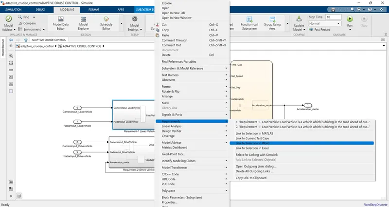
we are tagging the given data in challange and connecting with the simulink model by selecting the required subsytems and right click and select the requirment and select the Link the selection in word to link the data.
SOLVER SETTINGS:
Solver settings is one of the most important to simulate the model.
To open the solver settings go o the modellind settings or use the command ctrl+E to open the medelling properties.
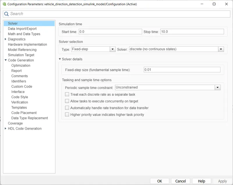
In that we are selecting the solver confriguration.
- click the solver to model the solver parameters.
- now change the type to fixed step and solver to discrete(no continuous states) and take sample trimes as 0.01 seconds. then click ok to save the sover confriguration.
In that same confriguration window the another setting to model, which is code generation click code generation
- choose the system target fike as ert.tlc by clicking on the browser option.
MAB Guidelines:
MAB guidlines are a set of modeling guidlines development by an industry working group method of a matlab, simulink, stateflow, and coder.
- To perform a the MAB guidlines test on our simulink model;, go to modeling section and select model advisor which is at the top left corner on simulink window.
- By using the model advisor to verfiy the compliance of your model with the mathworks MAB guidlines.
- In the model advisor there are many numbers of mab guidlines are there in that we are selecting the standard MAB gudlines alone.
- After selecting Mab click on run check box to run the MAB performance test .
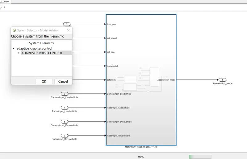
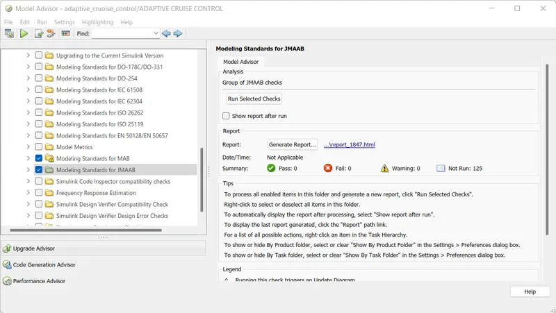
Now we are going to select the Run button on the window to perform the test.
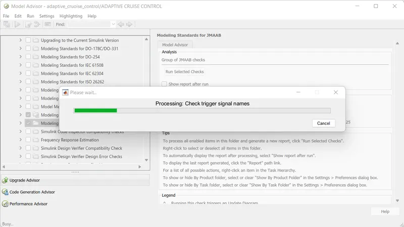
Now to performance test is running it will take some time completed the test.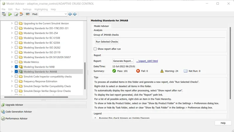
After that we have got the result as shown in above picture.
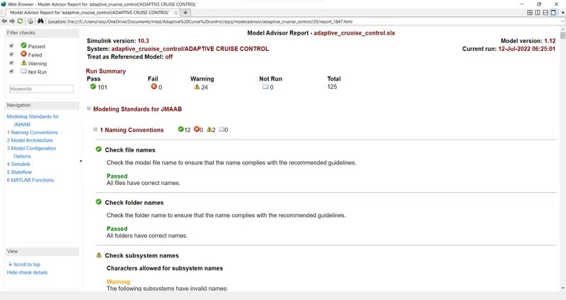
Report for the performance test:
Creation of C-Codings:
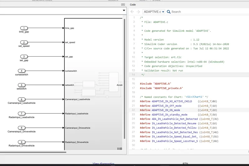
Codings: