Project 2 Adaptive Cruise Control
Aim-
- Developing Adaptive Cruise Control feature as per the Requirement Document using MATLAB Simulink.
- Analyse the MBD related processes: Requirement Tagging & Traceability, SLDD creation, Configuration Parameter changes, Model Advisor check & Code Generation.
Adaptive Cruise Control Feature for passenger cars allows the host vehicle to adapt to the speed in line with the flow of traffic. Driving in heavy traffic or keeping a safe distance to the preceding vehicle calls for a high level of concentration. The Adaptive Cruise Control feature can reduce the stress on the driver by automatically controlling the vehicle speed & maintaining a predefined minimum distance to the preceding vehicle. As a consequence, the driver enjoys more comfort & can concentrate on the road little better.
Congestion is a serious issue all around the world. The optimization of traffic networks is a difficulty for major cities all over the world. Even at modest speeds, driving bumper to bumper can cause not just annoyance for drivers, but also accidents. Stop & Go cruise control can help in this situation. The difference is in slow-moving traffic, where it automatically pauses or starts vehicle movement under driver supervision, comparable to adaptive cruise control on highways. While maintaining a safe distance from the vehicle in front, the automobile will brake and accelerate on its own.
Sensory technology installed in automobiles, including as cameras, lasers, and radar equipment, allows ACC to calculate the distance between two cars or other objects on the road. As a result, ACC is the foundation for future car intelligence.
The car can identify and warn the driver about probable forward crashes thanks to these sensory systems. As a result, red lights flash and the phrase 'brake now!' appears on the dashboard to assist the driver in slowing down. There may be an audible warning as well.
A radar sensor is usually at the core of the Adaptive Cruise Control. Installed at the front of the vehicle, the system permanently monitors the road ahead. As long as the road ahead is clear, cruise control feature maintains the speed set by the driver. If the system spots a slower vehicle within its detection range, it gently reduces speed by releasing the accelerator or actively engaging the brake control system. If the vehicle ahead speeds up or changes lanes, the cruise control automatically accelerates to the driver’s desired speed.We have the main model.
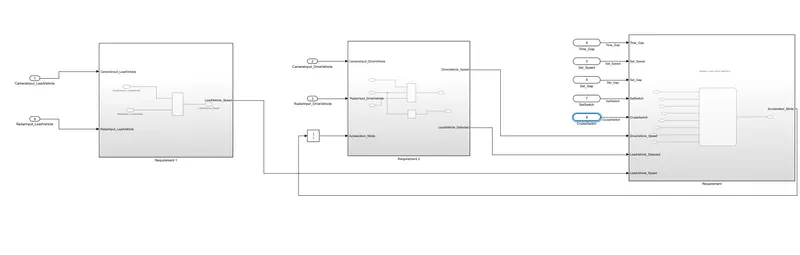
For the system we have 3 subsystem ,which are requirement 1 which is dealing with the lead vehicle parameters and the rquirement 2 consist of the drive vehicle parameter.And the third subsystem is the system which is the adaptive control algorithm which consist of stateflow.
In requirement 1 we have,
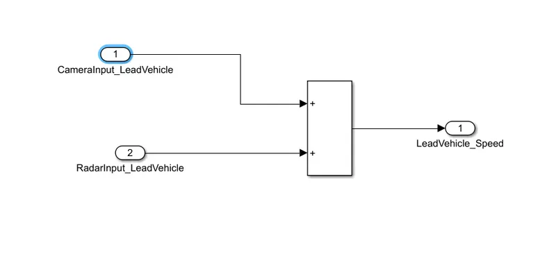
We have the inputs from the radar and the camera for the lead vehicle,CameraInput_LeadVehicle & RadarInput_LeadVehicle.Ideally sensor fusion techniques will be deployed to process & analyze data from camera & radar. We are not taking that,We are adding these signal using addition block and The output is given as LeadVehicle_Speed.
In requirement 2 we have the drive vehicle parameters,
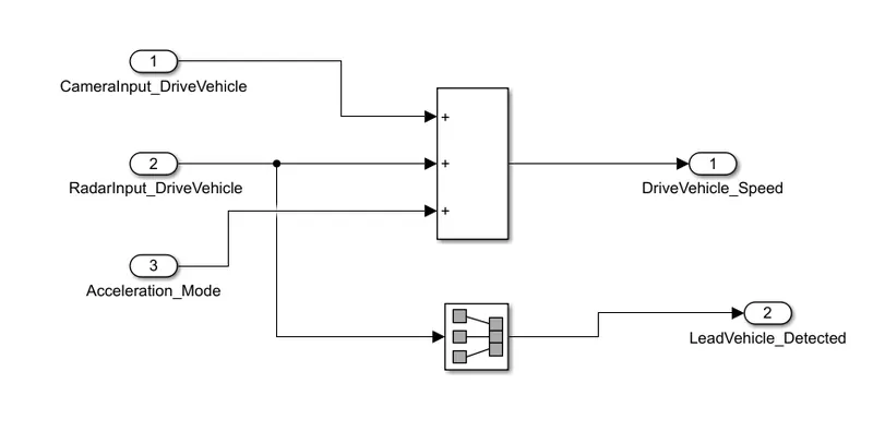
There are three inputs in this requirement , CameraInput_DriveVehicle, RadarInput_DriveVehicle) & one signal coming as an Input to this subsystem (Signal Name: Acceleration_Mode) – .Like the above requirement, sensor fusion techniques will also be deployed here, for complexity reasons we are ignoring them.Two output are coming from this subsystem (Signal DriveVehicle_Speed & LeadVehicle_Detected).Signal DriveVehicle_Speed is summation of three input signals mentioned above and using signal conversion block,LeadVehicle_Detected is renamed from Input Signal RadarInput_DriveVehicle.
In requirement 3 we have,
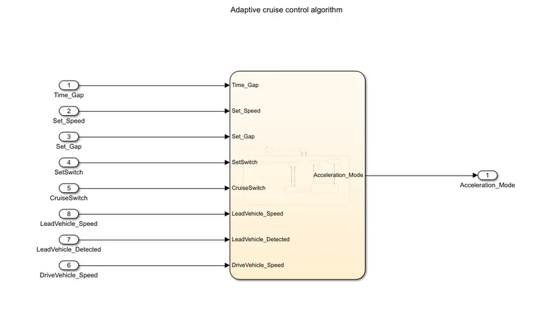
In this subsystem,stateflow is implemented and the inputs for the stateflow is Time_Gap, Set_Speed, Set_Gap, CruiseSwitch, SetSwitch and LeadVehicle_Detected,DriveVehicle_Speed,LeadVehicle_Speed,
We have to implement the stateflow as per given in our objective,SO we have 3 cases,ACC ON mode,ACC standby mode and ACC off mode,in that we have 6 different substates,These are implemented with the given conditions.
- LeadVehicle_Detected_Follow (Default)
- LeadVehicle_Not_Detected
- LeadVehicle_Detected_Resume
- LeadVehicle_Not_Detected_Resume
- LeadVehicle_Speed_lessthan_Set_Speed
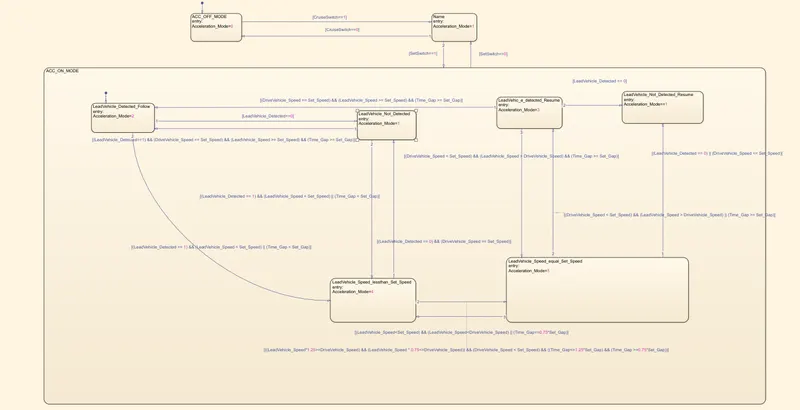
The output of this system is given as acceleration mode where it again goes to the input of the requirement 2 subsystem,By using signal delay block ,the signal is discretized with respect to the time for reducing the complexicity of the process.
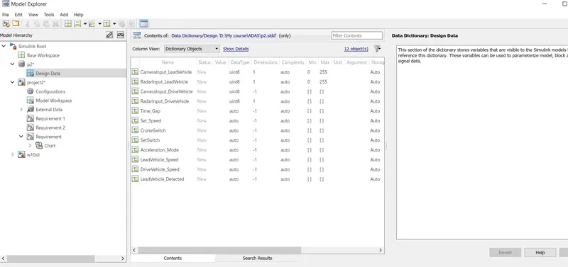
We have to link the parameters to a dictionary,for that we have to create a new sldd file ,from the model explorer we can configure the signal parameters,We have to create the given signal with theri given specifications,and link to the dictionary.
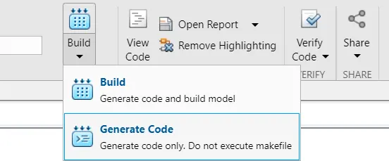
We have generated the code for the model,From the apps palette,we have a option called build and generate code for the model,by clicking it we will be generating the code.
#include "project2.h"

/* Named constants for Chart: '/Chart' */
#define IN_ACC_OFF_MODE                ((uint8_T)1U)
#define IN_ACC_ON_MODE                 ((uint8_T)2U)
#define IN_LeadVehic_e_detected_Resume ((uint8_T)1U)
#define IN_LeadVehicle_Detected_Follow ((uint8_T)2U)
#define IN_LeadVehicle_Not_Detected    ((uint8_T)3U)
#define IN_LeadVehicle_Not_Detected_Res ((uint8_T)4U)
#define IN_LeadVehicle_Speed_equal_Set_ ((uint8_T)5U)
#define IN_LeadVehicle_Speed_lessthan_S ((uint8_T)6U)
#define IN_NO_ACTIVE_CHILD             ((uint8_T)0U)
#define IN_Name                        ((uint8_T)3U)

/* Block signals and states (default storage) */
DW rtDW;

/* External inputs (root inport signals with default storage) */
ExtU rtU;

/* Real-time model */
static RT_MODEL rtM_;
RT_MODEL *const rtM = &rtM_;

/* Model step function */
void project2_step(void)
{
  real_T rtb_Add;
  real_T rtb_Add1;

  /* Sum: '/Add' incorporates:
   *  Inport: '/CameraInput_LeadVehicle'
   *  Inport: '/RadarInput_LeadVehicle'
   */
  rtb_Add = rtU.CameraInput_LeadVehicle + rtU.RadarInput_LeadVehicle;

  /* Sum: '/Add1' incorporates:
   *  Inport: '/ RadarInput_DriveVehicle'
   *  Inport: '/CameraInput_DriveVehicle'
   *  UnitDelay: '/Unit Delay'
   */
  rtb_Add1 = (rtU.CameraInput_DriveVehicle + rtU.RadarInput_DriveVehicle) +
    rtDW.Acceleration_Mode;

  /* Chart: '/Chart' incorporates:
   *  Inport: '/ RadarInput_DriveVehicle'
   *  Inport: '/CruiseSwitch'
   *  Inport: '/SetSwitch'
   *  Inport: '/Set_Gap'
   *  Inport: '/Set_Speed'
   *  Inport: '/Time_Gap'
   */
  if (rtDW.is_active_c3_project2 == 0U) {
    rtDW.is_active_c3_project2 = 1U;
    rtDW.is_c3_project2 = IN_ACC_OFF_MODE;
    rtDW.Acceleration_Mode = 0.0;
  } else {
    switch (rtDW.is_c3_project2) {
     case IN_ACC_OFF_MODE:
      rtDW.Acceleration_Mode = 0.0;
      if (rtU.CruiseSwitch == 1.0) {
        rtDW.is_c3_project2 = IN_Name;
        rtDW.Acceleration_Mode = 1.0;
      }
      break;

     case IN_ACC_ON_MODE:
      if (rtU.SetSwitch == 0.0) {
        rtDW.is_ACC_ON_MODE = IN_NO_ACTIVE_CHILD;
        rtDW.is_c3_project2 = IN_Name;
        rtDW.Acceleration_Mode = 1.0;
      } else {
        switch (rtDW.is_ACC_ON_MODE) {
         case IN_LeadVehic_e_detected_Resume:
          rtDW.Acceleration_Mode = 3.0;
          if ((rtb_Add1 == rtU.Set_Speed) && (rtb_Add >= rtU.Set_Speed) &&
              (rtU.Time_Gap >= rtU.Set_Gap)) {
            rtDW.is_ACC_ON_MODE = IN_LeadVehicle_Detected_Follow;
            rtDW.Acceleration_Mode = 2.0;
          } else if (rtU.RadarInput_DriveVehicle == 0.0) {
            rtDW.is_ACC_ON_MODE = IN_LeadVehicle_Not_Detected_Res;
          } else if ((rtb_Add1 < rtU.Set_Speed) && (rtb_Add > rtb_Add1) &&
                     (rtU.Time_Gap >= rtU.Set_Gap)) {
            rtDW.is_ACC_ON_MODE = IN_LeadVehicle_Speed_equal_Set_;
            rtDW.Acceleration_Mode = 5.0;
          }
          break;

         case IN_LeadVehicle_Detected_Follow:
          rtDW.Acceleration_Mode = 2.0;
          if (rtU.RadarInput_DriveVehicle == 0.0) {
            rtDW.is_ACC_ON_MODE = IN_LeadVehicle_Not_Detected;
            rtDW.Acceleration_Mode = 1.0;
          } else if (((rtU.RadarInput_DriveVehicle == 1.0) && (rtb_Add <
                       rtU.Set_Speed)) || (rtU.Time_Gap < rtU.Set_Gap)) {
            rtDW.is_ACC_ON_MODE = IN_LeadVehicle_Speed_lessthan_S;
            rtDW.Acceleration_Mode = 4.0;
          }
          break;

         case IN_LeadVehicle_Not_Detected:
          rtDW.Acceleration_Mode = 1.0;
          if ((rtU.RadarInput_DriveVehicle == 1.0) && (rtb_Add1 == rtU.Set_Speed)
              && (rtb_Add >= rtU.Set_Speed) && (rtU.Time_Gap >= rtU.Set_Gap)) {
            rtDW.is_ACC_ON_MODE = IN_LeadVehicle_Detected_Follow;
            rtDW.Acceleration_Mode = 2.0;
          } else if (((rtU.RadarInput_DriveVehicle == 1.0) && (rtb_Add <
                       rtU.Set_Speed)) || (rtU.Time_Gap < rtU.Set_Gap)) {
            rtDW.is_ACC_ON_MODE = IN_LeadVehicle_Speed_lessthan_S;
            rtDW.Acceleration_Mode = 4.0;
          }
          break;

         case IN_LeadVehicle_Not_Detected_Res:
          break;

         case IN_LeadVehicle_Speed_equal_Set_:
          rtDW.Acceleration_Mode = 5.0;
          if ((rtU.RadarInput_DriveVehicle == 0.0) || (rtb_Add1 <= rtU.Set_Speed))
          {
            rtDW.is_ACC_ON_MODE = IN_LeadVehicle_Not_Detected_Res;
          } else if (((rtb_Add1 < rtU.Set_Speed) && (rtb_Add > rtb_Add1)) ||
                     (rtU.Time_Gap >= rtU.Set_Gap)) {
            rtDW.is_ACC_ON_MODE = IN_LeadVehic_e_detected_Resume;
            rtDW.Acceleration_Mode = 3.0;
          } else if (((rtb_Add < rtU.Set_Speed) && (rtb_Add < rtb_Add1)) ||
                     (0.75 * rtU.Set_Gap == rtU.Time_Gap)) {
            rtDW.is_ACC_ON_MODE = IN_LeadVehicle_Speed_lessthan_S;
            rtDW.Acceleration_Mode = 4.0;
          }
          break;

         default:
          /* case IN_LeadVehicle_Speed_lessthan_Set_Speed: */
          rtDW.Acceleration_Mode = 4.0;
          if ((rtU.RadarInput_DriveVehicle == 0.0) && (rtb_Add1 == rtU.Set_Speed))
          {
            rtDW.is_ACC_ON_MODE = IN_LeadVehicle_Not_Detected;
            rtDW.Acceleration_Mode = 1.0;
          } else if ((rtb_Add * 1.25 >= rtb_Add1) && (rtb_Add * 0.75 <= rtb_Add1)
                     && (rtb_Add1 < rtU.Set_Speed) && (rtU.Time_Gap <= 1.25 *
                      rtU.Set_Gap) && (rtU.Time_Gap >= 0.75 * rtU.Set_Gap)) {
            rtDW.is_ACC_ON_MODE = IN_LeadVehicle_Speed_equal_Set_;
            rtDW.Acceleration_Mode = 5.0;
          }
          break;
        }
      }
      break;

     default:
      /* case IN_Name: */
      rtDW.Acceleration_Mode = 1.0;
      if (rtU.CruiseSwitch == 0.0) {
        rtDW.is_c3_project2 = IN_ACC_OFF_MODE;
        rtDW.Acceleration_Mode = 0.0;
      } else if (rtU.SetSwitch == 1.0) {
        rtDW.is_c3_project2 = IN_ACC_ON_MODE;
        rtDW.is_ACC_ON_MODE = IN_LeadVehicle_Detected_Follow;
        rtDW.Acceleration_Mode = 2.0;
      }
      break;
    }
  }

  /* End of Chart: '/Chart' */
}

/* Model initialize function */
void project2_initialize(void)
{
  /* (no initialization code required) */
}

/*
 * File trailer for generated code.
 *
 * [EOF]
 */
From the model advisor,we can proceed with the model advisor check,where it checks the model where it should fllows the MAB standards,
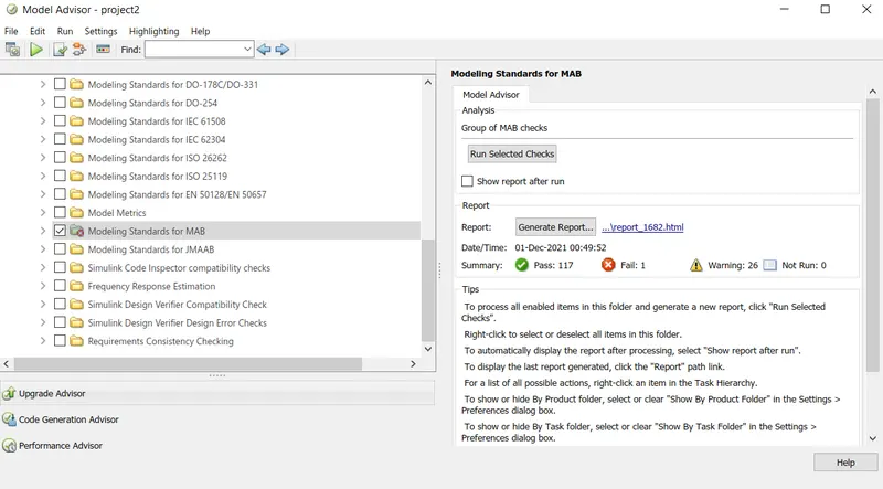
We can generate the report of the model by clicking the option of generate report where it is saved as a file.
Conclusion-
A adaptive cruise control model is created using matlab with speficied conditions and simulations were done.