Project 2 Adaptive Cruise Control
Objective of Main Project:
- Developing Adaptive Cruise Control feature as per the Requirement Document using MATLAB Simulink.
- Follow all the MBD related processes: Requirement Tagging & Traceability, SLDD creation, Configuration Parameter changes, Model Advisor check & Code Generation.
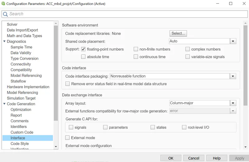
- In Configuration Parameters: enable “Support Floating Numbers” under Code Generation settings.
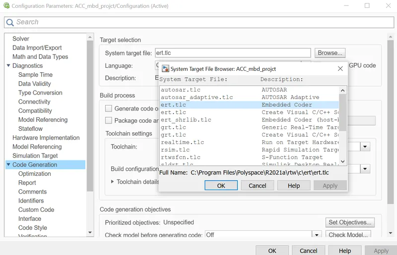
- Use Embedded Coder to generate the code.
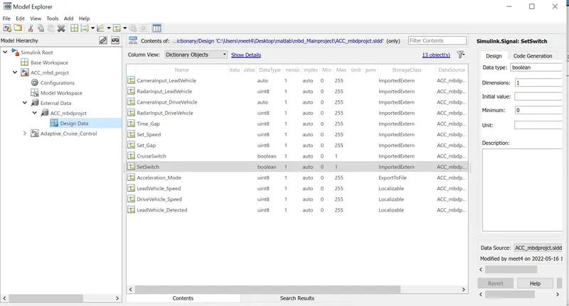
- If choosing code generation, Storage class for Input signals: ImportedExtern; Storage class for Output signal: Export to File; Storage class for local signals: localizable; Storage class for calibration signals: Const.
- Choose sample time for all signals as 0.01s
General Overview:
Adaptive Cruise Control Feature for passenger cars allows the host vehicle to adapt to the speed in line with the flow of traffic. Driving in heavy traffic or keeping a safe distance to the preceding vehicle calls for a high level of concentration. The Adaptive Cruise Control feature can reduce the stress on the driver by automatically controlling the vehicle speed & maintaining a predefined minimum distance to the preceding vehicle. As a consequence, the driver enjoys more comfort & can concentrate on the road little better.
A radar sensor is usually at the core of the Adaptive Cruise Control. Installed at the front of the vehicle, the system permanently monitors the road ahead. As long as the road ahead is clear, cruise control feature maintains the speed set by the driver. If the system spots a slower vehicle within its detection range, it gently reduces speed by releasing the accelerator or actively engaging the brake control system. If the vehicle ahead speeds up or changes lanes, the cruise control automatically accelerates to the driver’s desired speed.
Standard Adaptive Cruise Control can be activated from speeds of around 30 km/h (20 mph) upwards and supports the driver, primarily on cross-country journeys or on freeways. The cruise control stop & go variant is also active at speeds below 30 km/h (20 mph). It can maintain the set distance to the preceding vehicle even at very low speeds and can decelerate to a complete standstill. When the vehicle remains stopped longer, the driver needs only to reactivate the system, for example by briefly stepping on the gas pedal to return to cruise control mode. In this way, cruise control stop & go supports the driver even in heavy traffic and traffic jams.
Since Adaptive Cruise Control is a comfort and convenience system, brake interventions and vehicle acceleration only take place within defined limits. Even with Adaptive Cruise Control switched on, it remains the driver’s responsibility to monitor the speed and distance from the vehicle in front.
Steps Involved:
- Create SLDD file with the given datas:
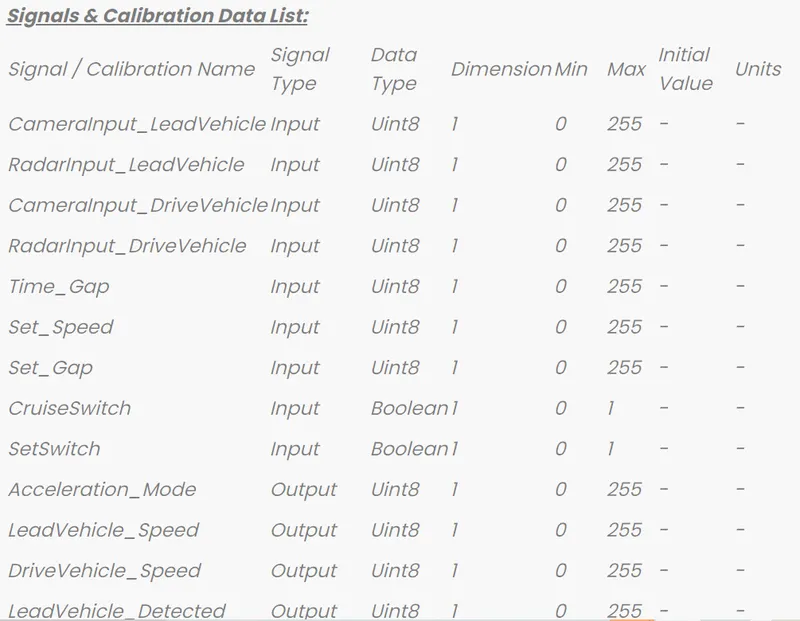
Simulink Data Dictionary (SLDD):
Data Dictionary file required for all signals/ parameters used by MBD feature; additional signal / parameter attributes required for MBD. MBD feature Data Dictionary is managed in 3 different formats: SLDD-file, m-file, mat-file.
Create SLDD file:
- Click on modeling--link to data dictionary--browse and select--ok.
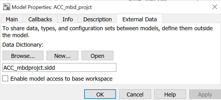
- Model explorer SLDD
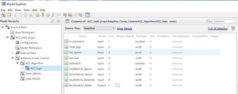
- Model explorer ACC Logic
Simulink model:
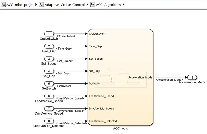
Create a subsystem called adaptive cruise control and again create 3 subsystems inside it according to the requirements given. There are 9 input signals and an output signal. Connect required number of inports and outports to the subsystems and name it accordingly.
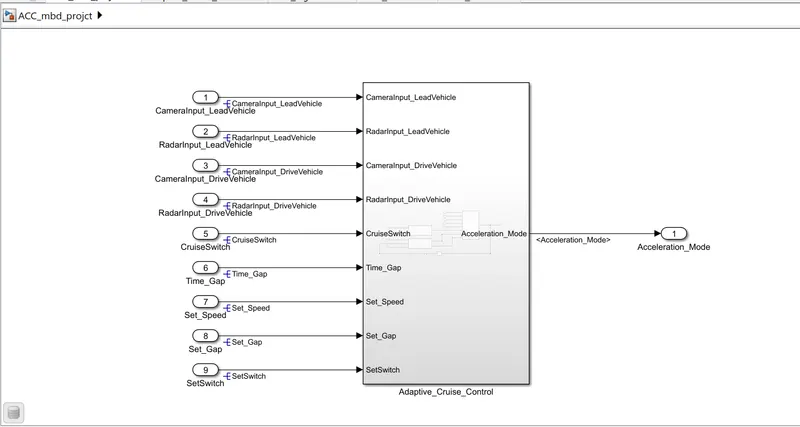
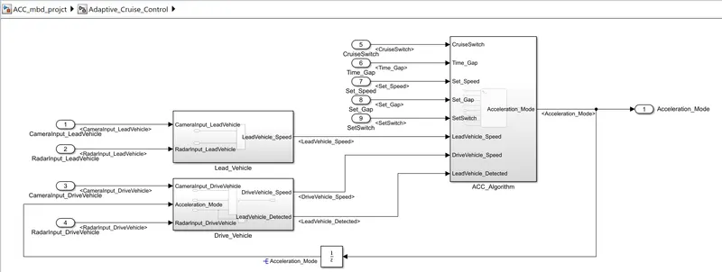
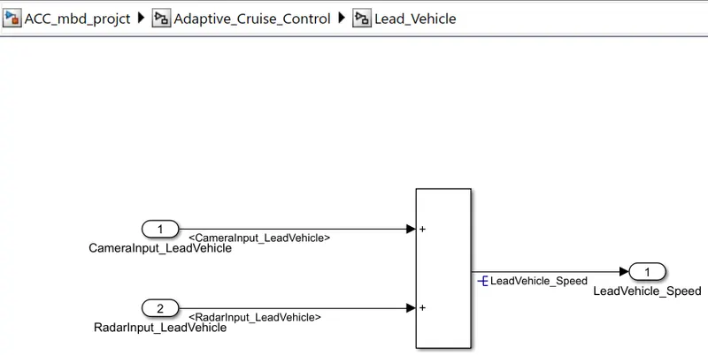
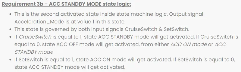
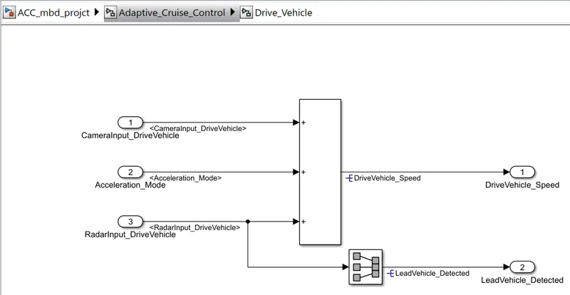
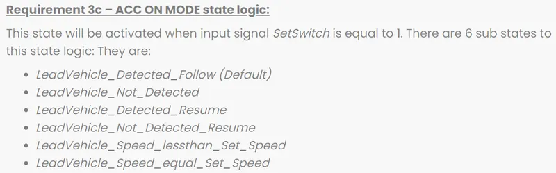
Chart: A stateflow chart contains either;
State diagrams: A chart that contains states.
Flowcharts: A chart that doesnot use any states; uses only transition and conditions logic.
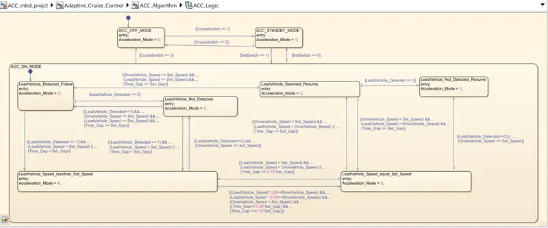
Requirement 3c (i) – LeadVehicle_Detected_Follow (ACC ON MODE):
- This is the default sub state inside ACC ON MODE state. Output signal Acceleration_Mode is equal to 2.
- Condition to transit from LeadVehicle_Detected_Follow to LeadVehicle_Not_Detected; Input signal condition LeadVehicle_Detected == 0.
- Condition to transit from LeadVehicle_Detected_Follow to LeadVehicle_Speed_lessthan_Set_Speed; Input Signals condition (LeadVehicle_Detected == 1) && (LeadVehicle_Speed < Set_Speed) || (Time_Gap < Set_Gap).
Requirement 3c (ii) – LeadVehicle_Not_Detected (ACC ON MODE):
- Output signal Acceleration_Mode is equal to 1.
- Condition to transit from LeadVehicle_Not_Detected to LeadVehicle_Detected_Follow; Input signals condition [(LeadVehicle_Detected==1) && (DriveVehicle_Speed == Set_Speed) && (LeadVehicle_Speed >= Set_Speed) && (Time_Gap >= Set_Gap)]
- Condition to transit from LeadVehicle_Not_Detected to LeadVehicle_Speed_lessthan_Set_Speed; Input signals condition [(LeadVehicle_Detected == 1) && (LeadVehicle_Speed < Set_Speed) || (Time_Gap < Set_Gap)]
Requirement 3c (iii) – LeadVehicle_Detected_Resume (ACC ON MODE):
- Output signal Acceleration_Mode is equal to 3.
- Condition to transit from LeadVehicle_Detected_Resume to LeadVehicle_Detected_Follow; Input signals condition [(DriveVehicle_Speed == Set_Speed) && (LeadVehicle_Speed >= Set_Speed) && (Time_Gap >= Set_Gap)]
- Condition to transit from LeadVehicle_Detected_Resume to LeadVehicle_Not_Detected_Resume; Input signal condition LeadVehicle_Detected==0.
- Condition to transit from LeadVehicle_Detected_Resume to LeadVehicle_Speed_equal_Set_Speed; Input Signal condition [(DriveVehicle_Speed < Set_Speed) && (LeadVehicle_Speed > DriveVehicle_Speed) && (Time_Gap >= Set_Gap)]
Requirement 3c (iv) - LeadVehicle_Not_Detected_Resume (ACC ON MODE):
- Output signal Acceleration_Mode is equal to 1.
Requirement 3c (v) - LeadVehicle_Speed_lessthan_Set_Speed (ACC ON MODE):
- Output signal Acceleration_Mode is equal to 4.
- Condition to transit from LeadVehicle_Speed_lessthan_Set_Speed to LeadVehicle_Not_Detected; Input signal condition [(LeadVehicle_Detected == 0) && (DriveVehicle_Speed == Set_Speed)]
- Condition to transit from LeadVehicle_Speed_lessthan_Set_Speed to LeadVehicle_Speed_equal_Set_Speed; Input signals condition [((LeadVehicle_Speed*1.25>=DriveVehicle_Speed) && (LeadVehicle_Speed * 0.75<=DriveVehicle_Speed)) && (DriveVehicle_Speed < Set_Speed) && ((Time_Gap<=1.25*Set_Gap) && (Time_Gap >=0.75*Set_Gap))]
Requirement 3c (vi) - LeadVehicle_Speed_equal_Set_Speed (ACC ON MODE):
- Output signal Acceleration_Mode is equal to 5.
- Condition to transit from LeadVehicle_Speed_equal_Set_Speed to LeadVehicle_Not_Detected_Resume; Input signal conditions is [(LeadVehicle_Detected == 0) || (DriveVehicle_Speed <= Set_Speed)]
- Condition to transit from LeadVehicle_Speed_equal_Set_Speed to LeadVehicle_Detected_Resume; Input signal conditions [(DriveVehicle_Speed < Set_Speed) && (LeadVehicle_Speed > DriveVehicle_Speed) || (Time_Gap >= Set_Gap)]
- Condition to transit from LeadVehicle_Speed_equal_Set_Speed to LeadVehicle_Speed_lessthan_Set_Speed; Input signals conditions [(LeadVehicle_Speed<Set_Speed)&&(LeadVehicle_Speed<DriveVehicle_Speed)||(Time_Gap==0.75*Set_Gap)]
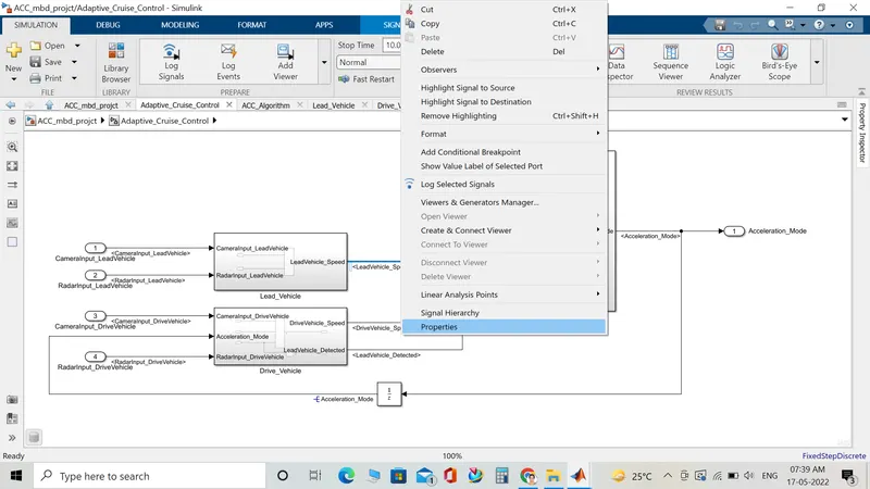
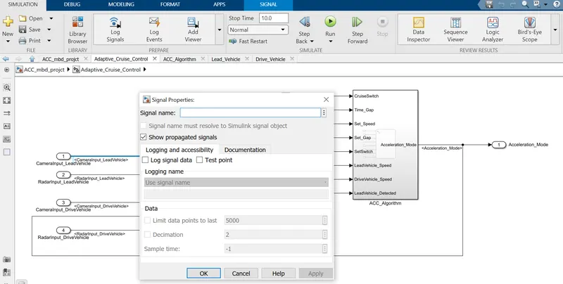
- Resolving and Propogating signal: Right click on model select properties, for the signal appearing first time give corresponding the signal name and resolve it. For signal appearing second time in model select on propagate signal option.
Requirement Tagging:
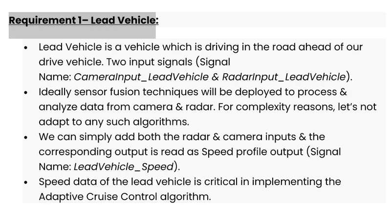
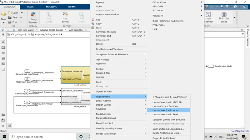
Requirements are provided as word documents and are saved in the working folder. It is tagged to their corresponding subsystem in model. First select the requirement 1 heading and highlight it and then go to model -- right click-- select requirements-- link to selection in word.
For each subsystem or block corresponsing requirement functionality from the document can be tagged for better understanding. Subsystem or components which are tagged with requirements, when selected gets highlighted to yellow color.
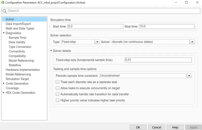
Simulink Model setting: Solver and code generation
- Under solver selection keep solver type as fixed step
- Fixed step size as 0.01
- Select Solver as discrete
- Under code generation select embedded coder
- Under Interface -- support-- uncheck all the box and select floating point numbers only.
Check for Modeling Standards:
MAB (Mathworks Advisory Board): The MAB Guidelines are a set of modeling guidelines developed by an independent industry working group for the usage of MATLAB®, Simulink®, Stateflow® and Embedded Coder®. The guidelines are the culmination of years of engineering expertise and best practices for developing, maintaining and documenting control algorithm models used in the development of production software.
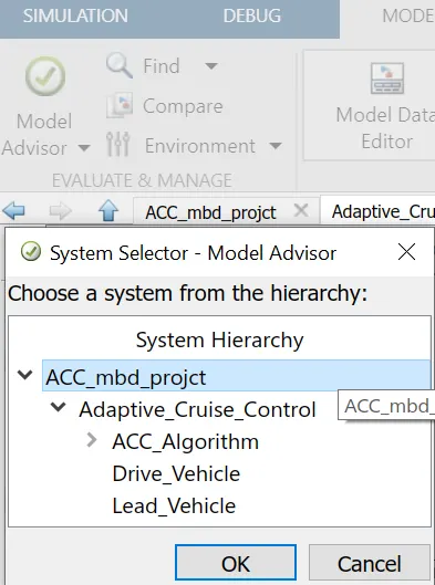
- Go to model advisor--choose system--select modeling standard for MAB
- Tick on modeling standard for MAB and run selected checks.
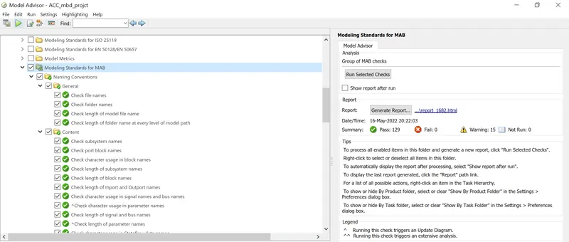
- Model advisor report : It shows that there is no failed test cases.
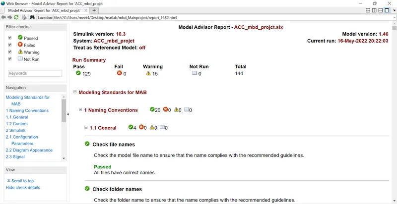
- Now finally download the report by clicking on generate report option.
Code generation:
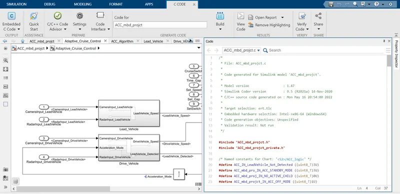
- Now to generate code click on Apps-- Select embedded coder.
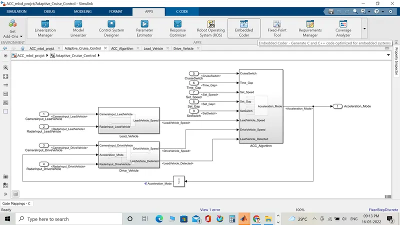
- Now select on build option.
- Adaptive Cruise Control code is generated as shown.
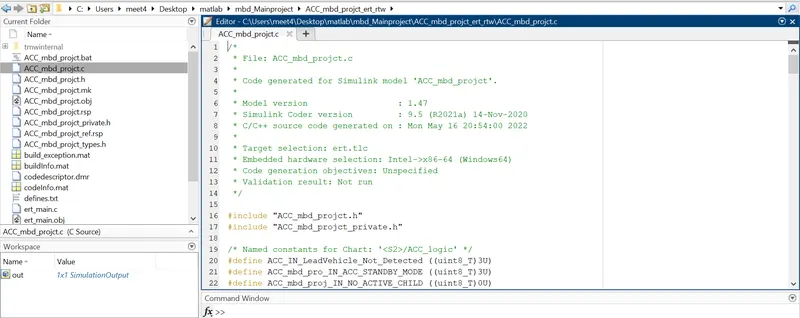
- We can also access the code from current folder.
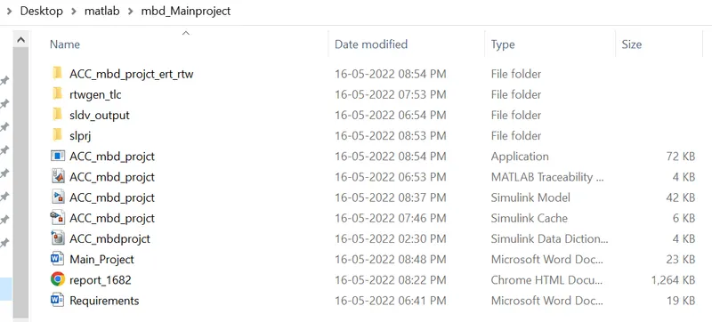
- These are files we will be having at the end of simulation.
Result:
- Created SLDD file from the given datas.
- Created the model from the requirements given.
- Resolved and propogated signals.
- Done requirement tagging.
- Configured model parameters.
- Checked for modeling standards- MAB guidelines.
- Run the selected checked under MAB guidelines and generated the model advisor report.
- The report shows there are 0 failed checks.
- Developed C code for Adaptive Cruise Control.