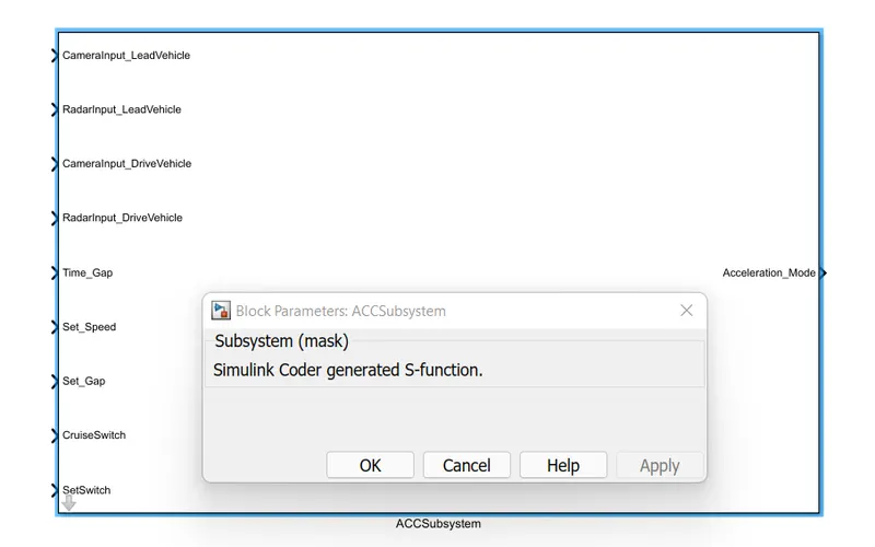
Project 2 Adaptive Cruise Control
Steps:
- Create requirement documents from 1 to 3c(vi)
- Create the main subsystem with 9 inputs and one output i.e. Acceleration mode:
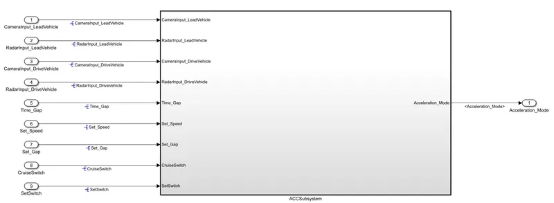
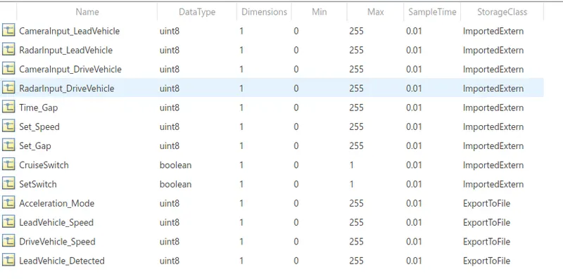
- Create SLDD and declare all the signals as per the given list and sample time is 0.01s for all
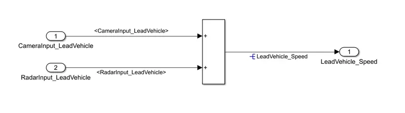
- As per requirement 1, create a subsystem and add the RADAR and Camera signals to give leadvehicle_detected signal as output
- As per requirement 2, create a subsystem to take camera and RADAR input for drive vehicle with acceleration feedback and give two outputs DriveVehicle_Speed and LeadVehicle_Detected
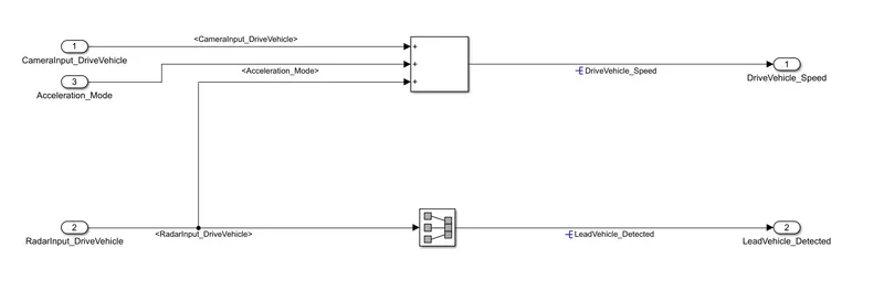
- A signal conversion block is used to copy the signal from RadarInput_DriveVehicle to LeadVehicle_Detected
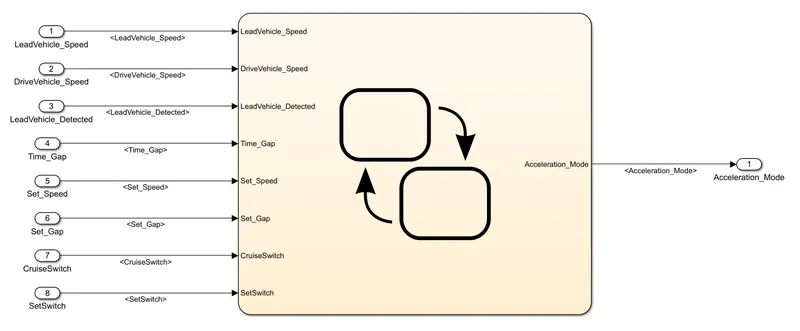
- As per requirement 3, create a subsystem to take 8 signal inputs and gives output as Acceleration_Mode
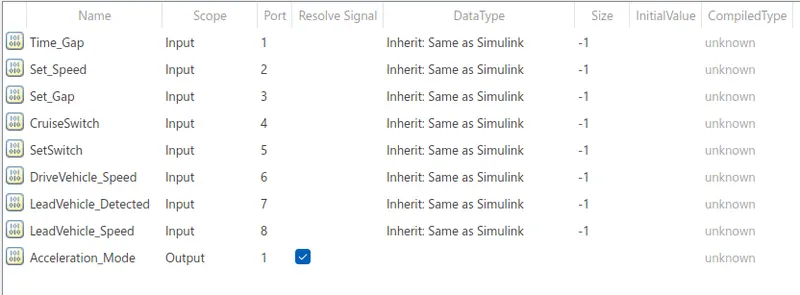
- In the model explorer, add the stateflow signals
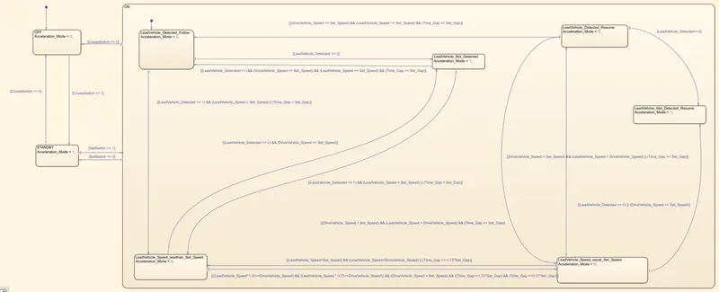
- As per Requirements 3(c) to 3c(vi), the following chart is prepared
- The output Acceleration_Mode is sent via a unit delay block back to Requirement 2 subsystem

- All the signals and propagated and input and output signals are resolved
- The model configuration parameters are set as per standard
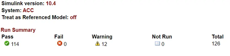
- Using Model Advisor, model checks are done as per ISO26262, JMAAB and MAB guidelines
- As per the warnings, the parameters are changed to minimise warnings and no errors were found
- To generate code, the main subsystem is treated as an Atomic unit
- S-function is generated from the subsystem and .c and .h files are generated with no errors