Project 1 (Mini Project on Vehicle Direction Detection
Steps:
- Create 2-word documents with requirement 1 and requirement 2
- As per the 2 requirements, there are two inputs: yaw rate and camera signal and one output: Vehicle_Direction_Indicator
- A subsystem called Vehicle _Direction_Detection is created with the above input and output
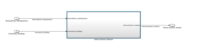
- Inside the subsystem, A subsystem named Turn_Compare is created as per Requirement 1 and linked to the doc file.
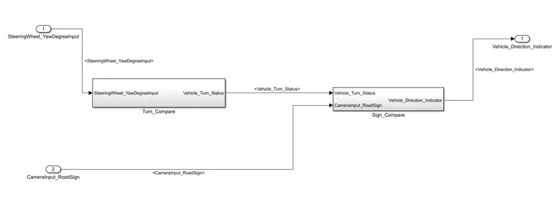
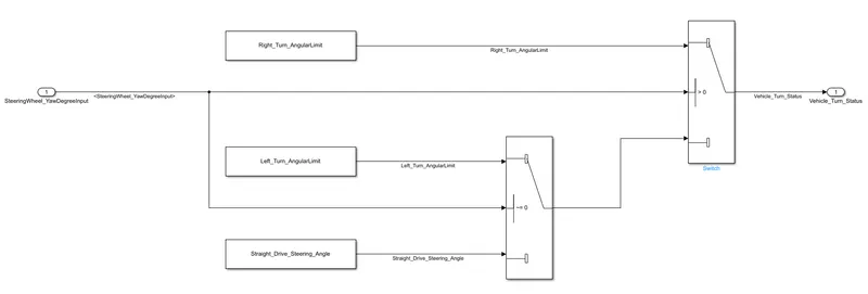
- Turn_Compare subsystem takes SteeringWheel_YawDegreeInput as and it is compared with the calibration signals as follows:
- If yaw degree > 0; Vehicle_Turn_Status = Right_Turn_AngularLimit
- else if yaw degree < 0; Vehicle_Turn_Status = Left_TurnAngularLimit
- else Vehicle_Turn_Status = Straight_Drive_Steering_Angle which is equal to 0
- Inside the Vehicle _Direction_Detection subsystem, A subsystem named Sign_Compare is created as per Requirement 2 and linked to the doc file.
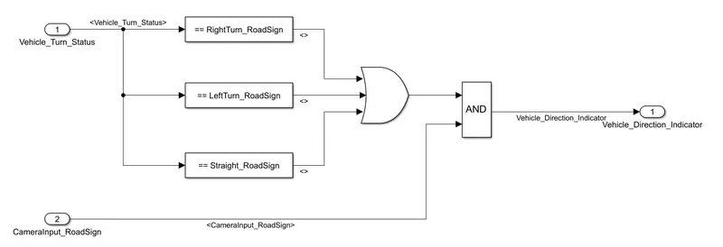
- Sign_Compare subsystem takes Vehicle_Direction_Indicator as and it is compared with the calibration signals as follows:
- If yaw degree == (RightTurn_RoadSign or LeftTurn_RoadSign or Straight_RoadSign); the output is 1
- If the CameraInput_RoadSign == 1, it gives a confirmation that there is a road sign actually present
- If the camera sign == 1 and Road sign == 1; it indicates that the vehicle is in the correct direction, else, if the output is 0, then the vehicle is in the wrong direction.
- After that, we can create the SLDD as per the given signals.
- After the subsystem is converted to Atomic unit, a SIL Test Harness is created, and signals are uploaded in the signal builder, and the result is displayed as follows:
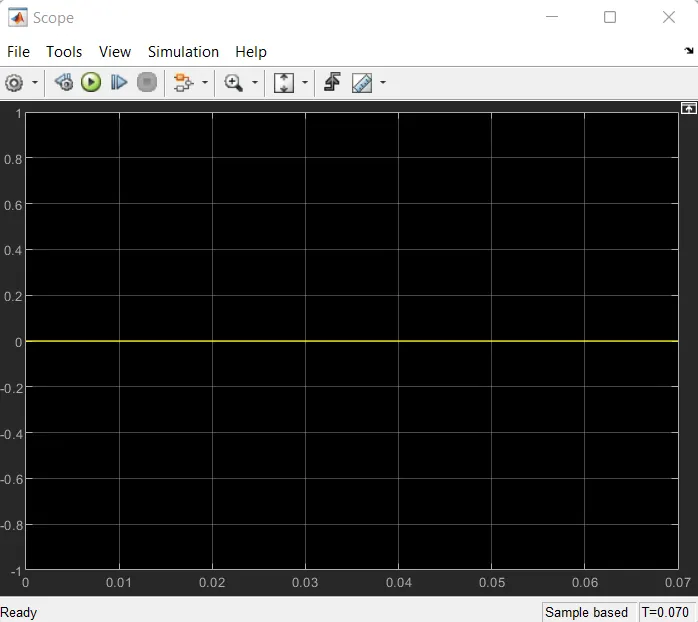
- Ensuring 0 throughout means the model is working as expected.