Project 2
Given Data:
1. Span of Bridge = 10m
2. Width of Deck Slab = 10.5m & Thickness of Deck Slab = 1.5m
3. Height of Pier = 12m
4. Size of Pier = 1.2 x 1.2 m & Size of Cross Beam = 0.75 x 1.2 m
5. The deck of the slab is supported by four I Girders. Each I Girder is 1.6 m height with a top and bottom flange width of 2m. The thickness of flange and web is 0.3m
6. The maximum crest elevation for the wave = 3 m
7. Assume constant r = 5
8. Assume Cva = 3
9. The Storm elevation = 8.5m
10.Cr = 0.4
11. The high flood level is 4 m above the Bottom of foundation level
12. The mean velocity of the river is 2.5 m/s.
13. The bridge is subjected to a live load of Class 70R tracked vehicle and radius of curvature in the bridge is 2 m.
14. The design speed of the vehicles is 50 km/hr
15. The deck of bridge is flat with B <30 degree. The depth of accumulation of snow is 1250 mm.
16. The Dead weight tonnage of Panamax vessel is 25000 DWT
17. Speed of the Barge = 60Km/hr = 16.7 m/sec (Assumed)
18. Hydrodynamic coefficient = 1.25 (Assumed)
Temperature load for the RC bridge with M40 grade to be constructed in Delhi (Assumed)
Calculating the water current forces ,centrifugal forces, wave forces, snow loads, temperature loads, Barge Impact load as per given data.
Staad Pro Modelling:
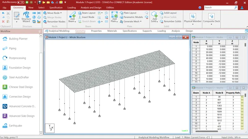
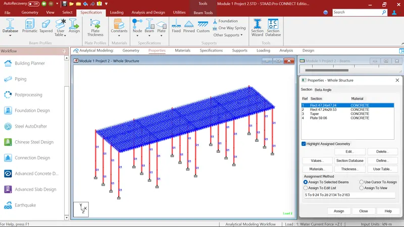
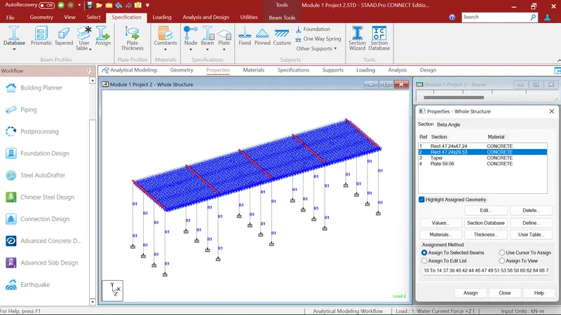
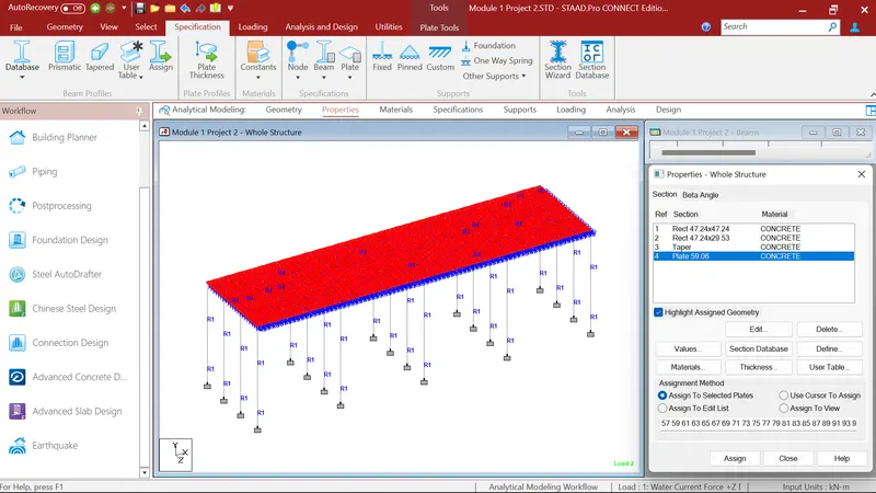
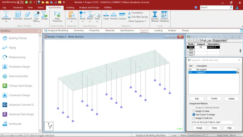
First I created the model in staad pro as per the given data. Where I modeled my bridge as per the given data. After that I defined the properties as per given data, then I provide fixed support to the piers.

Water Current Forces load Calculation:
As per IRC: 6-2014, P = 52KV2
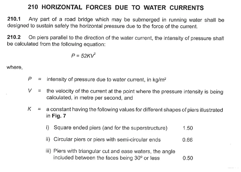
As I have Sqaure piers so shape factor K = 1.50
Height of H.F.L from foundation is 4m so water forces will be acting at 4m height of piers so,
Maximum Velocity, V = □">√2x Vmean
Mean Velocity = 2.5 m/sec (Given)
So, V = square root`2 x 2.5
V= 3.53
Water Current Force, P = 52 x K X V2
= 52 x 1.50 x 3.53 x 3.53
P = 971.9 kN/m2
As Pier size is 1.2m x 1.2m, so final P = 1.2 X 971.9 = 1166.28kN/m2
Staad Pro Water Current Force Load and Analysis:
After that I define the load cases. Where I defined two load cases for my structure.
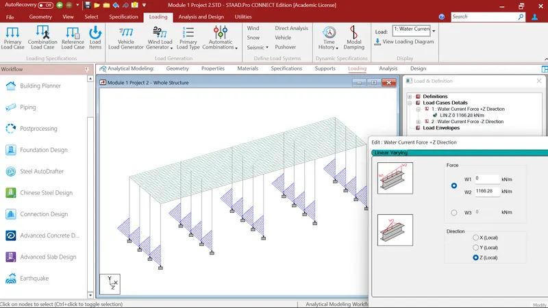
Load case 1: I go to the load case 1 where i go to member load then linear varying load. And gave load W2=1166.28kN/m2 in local Z direction and assigned it to the pier at a height of 4m.
Load case 2: I go to the load case 2 where i go to member load then linear varying load. And gave load W2=-1166.28kN/m2(For opposite direction) in local Z direction and assigned it to the pier at a height of 4m.
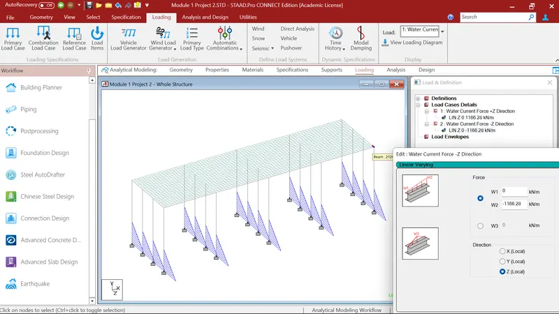
After that I gave the run analysis command and goes to the Post Processing mode.
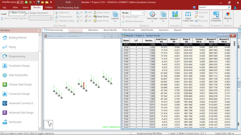
Where i firstely select the Beams and go to the reports, section forces and checked for the Maximum Bending Moment in MY for load cases. Where I got maximun bending moment in MY 2867.737kN-m.
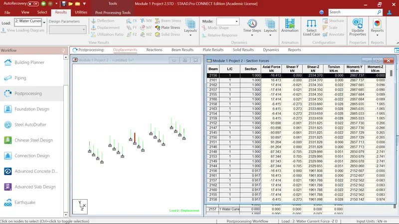
After that i again select the Beams and go to the reports, section forces and checked for the Maximum Bending Moment in MZ for load cases. Where I got maximun bending moment in MZ 2.741kN-m
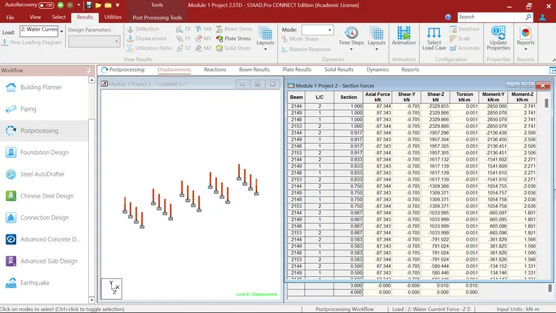
After that i again select the Beams and go to the reports, section forces and checked for the Maximum Shear Force in FY for load cases. Where I got maximun Shear Force in FY 0.705kN
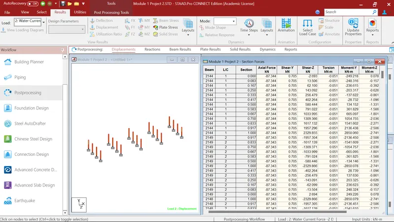
After that i again select the Beams and go to the reports, section forces and checked for the Maximum Shear Force in FZ for load cases. Where I got maximun Shear Force in FZ 2334.37kN.
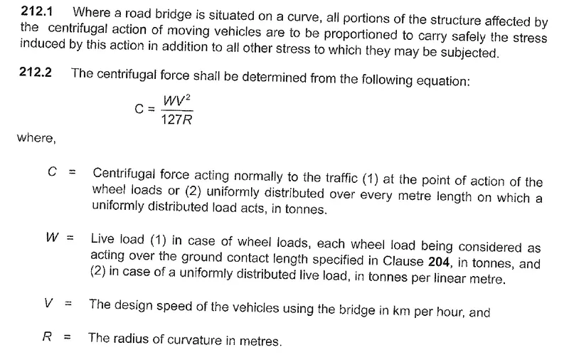
Centrifugal Load Calculation: As per IRC 6 -2016, Centriffugal load is given as
C = WV2/127R
C = (70 x 50 x 50) / (127 x 2)
C = 688.97 kN
Staad Pro Centrifugal Load and Analysis:
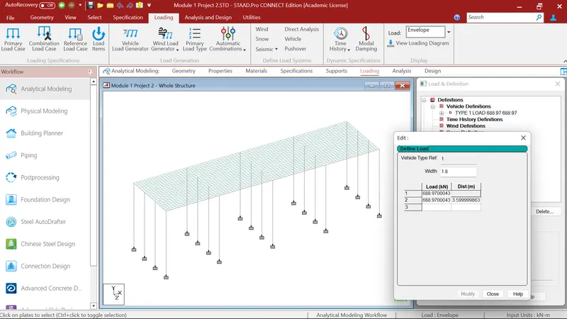
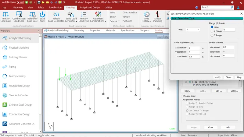
After that I applied the centrifugal force. Fo that I go to loading, load definition, in load definition I select vehicle definition where i defined the vehicle width 1.8m, centrifugal load 688.97kN at 3.6m distance. After that I go to Load case details where I generated 90 load generations. After that I defined X,Y,Z Cordinates with an x increment of 0.5.
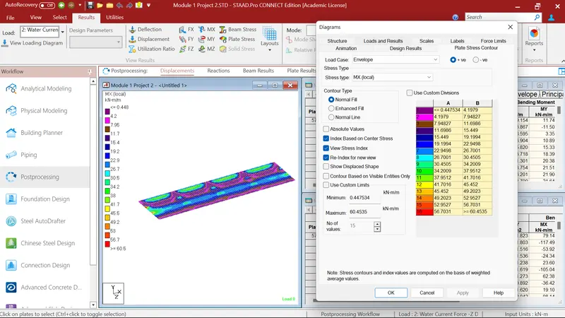
After that I gave the run analysis command and goes to the Post Processing mode. Where I select the Deck Slab and goes to the plate results for that I choose load cases of centrifugal forces and stress type MX i.e. bending moment in X direction. Where I got Maximum Bending moment of 60.45 kN-m/m
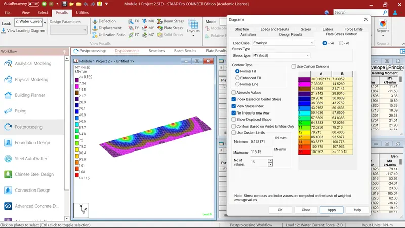
After that I again select the Deck Slab and goes to the plate results for that I again choose load case of centrifugal forces and stress type MY i.e. bending moment in Y direction. Where I got Maximum Bending moment of 115.15 kN-m/m
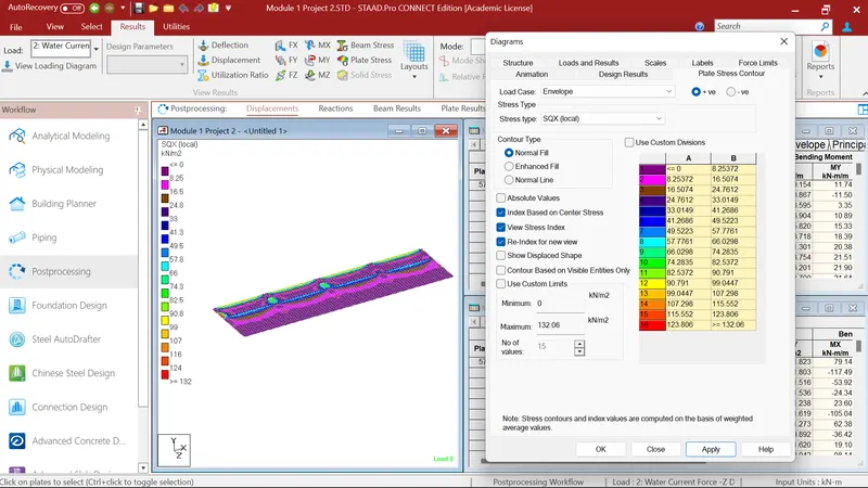
After that I again select the Deck Slab and goes to the plate results for that I again choose load case of centrifugal forces and stress type SQX i.e. Shear Force in X direction. Where I got Maximum Shear Force of 132.06 kN-m/m
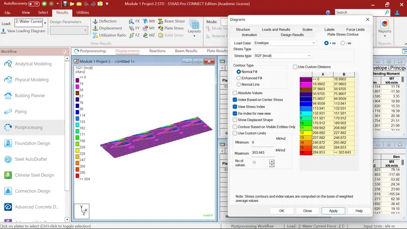
After that I again select the Deck Slab and goes to the plate results for that I again choose load case of centrifugal forces and stress type SQY i.e. Shear Force in Y direction. Where I got Maximum Shear Force of 303.843 kN-m/m
Wave Forces Calculation:
Max creast = 3m
δ">δδZh = ηmax - Centriod of I Girder`
= 3 - (1.6/2)
= 2.2m
δ">δδZv = ηmax - Elevation of bottom deck slab
= 3 - 0.75
= 2.25m
Vertical Load, Fv = r x delta Zv x AV
= 5 x 2.25 x ( 10.5 x (1.6/2)
= 94.5 kN
Horizontal Load, Fh = r x delta Zh x Ah
= 5 x 2.3 x (3 x 10)
= 345 kN
Maximum vertical load, Fvmax = cva x Fv
= 3 x 96.5
= 289.5 kN
Maximun Horizontal load, Fhmax = (1+Cr(N-1)xCva x Fh
= (1+0.4(3-1)x3x345
= 829 kN
Staad Pro Wave Load Analysis:
After that I go to the load case details where I first defined the Wave load. In wave load I go to the nodal load where I first defined the maximum horizontal load 829kN in Fz direction which I calculated earlier. After that I select the two nodes in x direction and assigned it to the selected nodes.
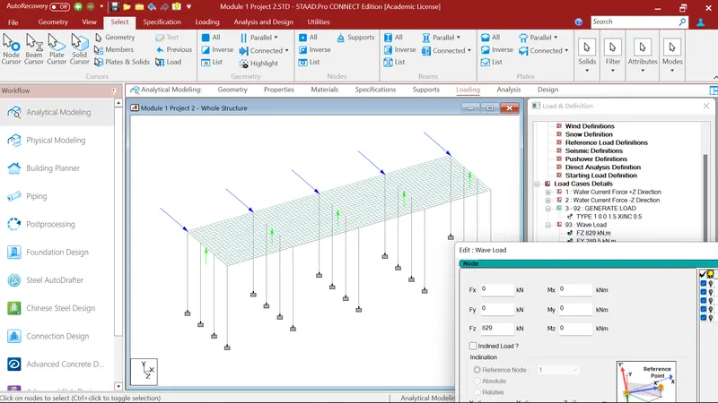
After that I again go to the nodal load where I first defined the maximum vertical load 289.5kN in Fy direction which I calculated earlier. After that I select the two middle nodes in each bay in x direction and assigned it to the selected nodes.
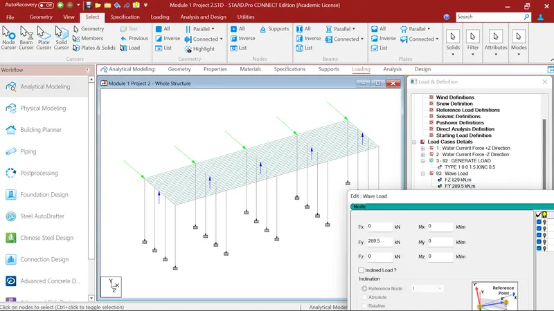
After that I run the analysis command and go to the post processing mode. Where I 1st select the deck slab plates. And checked for the maximun bending moment in Mx direction. Where maximum bending moment in Mx direction is -748.23kN-m/m.
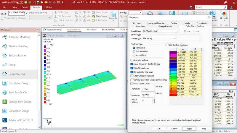
After that I again select the deck slab plates. And checked for the maximun bending moment in MY direction. Where maximum bending moment in MY direction is -71.168kN-m/m.
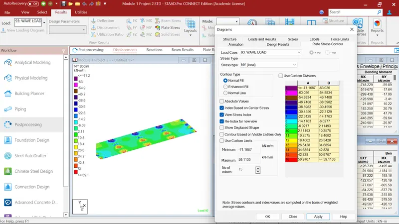
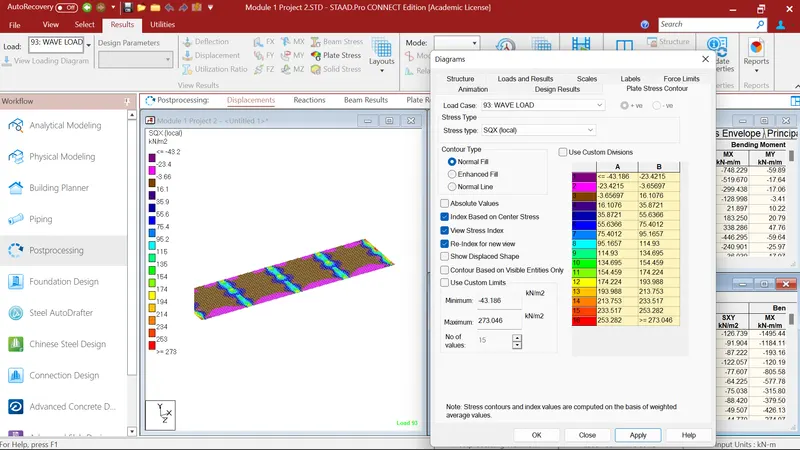
After that I again select the deck slab plates. And checked for the maximun shear force in SQX direction. Where maximun shear force in SQX direction is 273.046kN/m2.
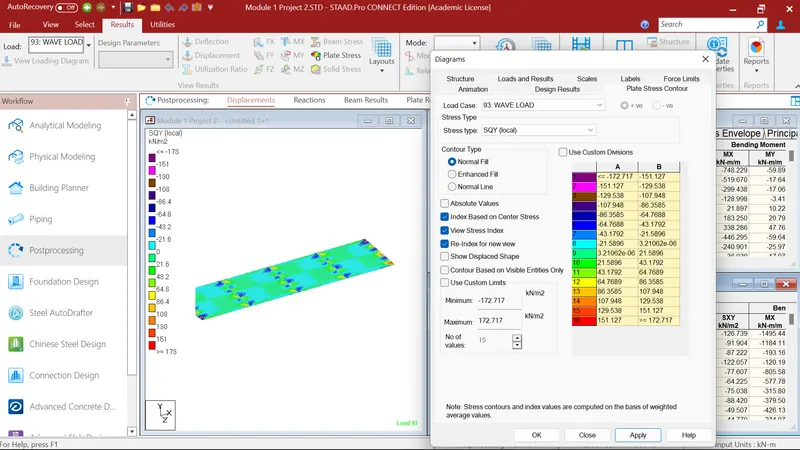
After that I again select the deck slab plates. And checked for the maximun shear force in SQY direction. Where maximun shear force in SQY direction is 172.717kN/m2
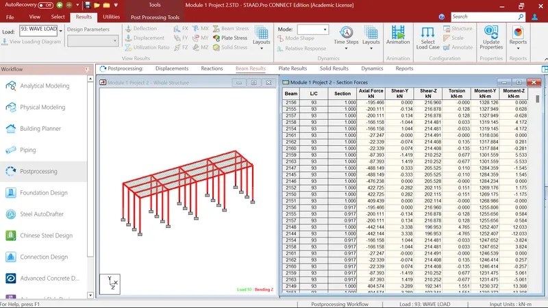
After that I go to the beam result where I select the whole structure having beam element. After that I go to the section forces where i checked for maximun bending moment in MY direction. Where I got maximun bending moment 1328.126kN-m in MY direction.
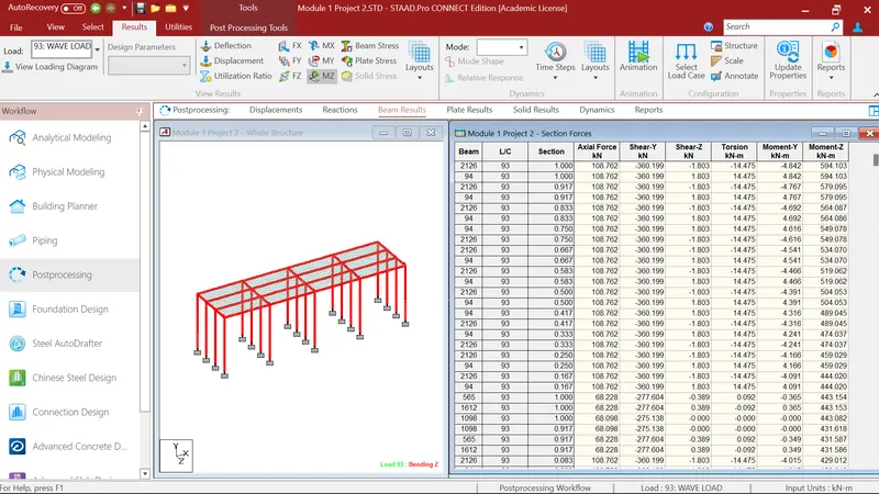
After that I again go to the section forces where i checked for maximun bending moment in MZ direction. Where I got maximun bending moment 594.103kN-m in MZ direction.
After that I again go to the section forces where i checked for maximun shear force in FY direction. Where I got maximun shear force 93.605kN in FY direction.
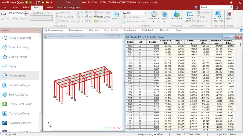
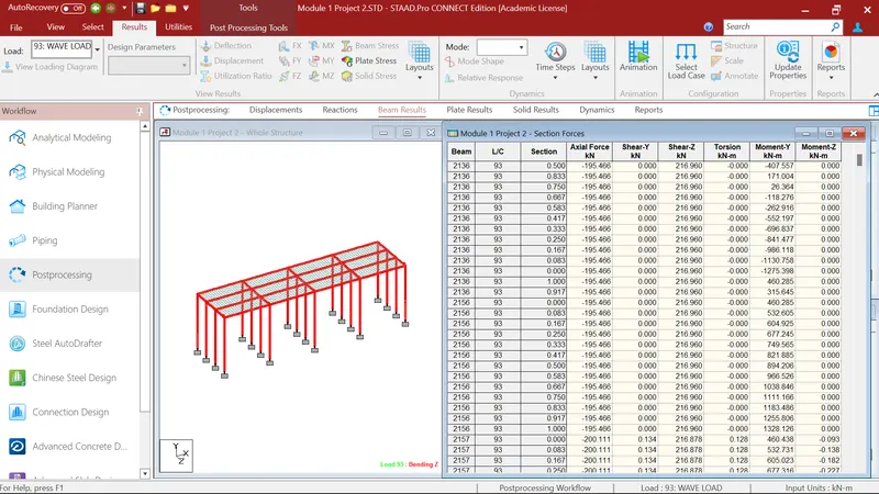
After that I again go to the section forces where i checked for maximun shear force in FZ direction. Where I got maximun shear force 216.960kN in FZ direction.
Snow Load Calculation:
Density of setteled snow = 2.5 kN/m3
Depth of snow = 1.25m
Deck of bridge is flat with β <30 degree
Snow load, So = 2.5 x 1.25 x 10
So = 31.25kN/m
Shape coefficient from As per IS: 875 (Part 4 )- 1987
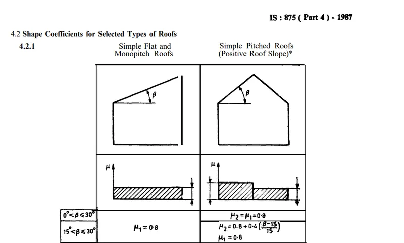
For β < 30 degree, μ1 = 0.8
Design Snow Load, S = μ x So
As per IS: 875 (Part 4 )- 1987
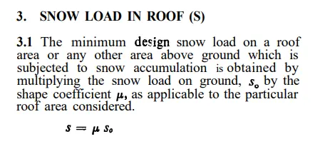
S = 0.8 x 31.25 = 25 kN/m
Staad Pro Snow load Analysis:
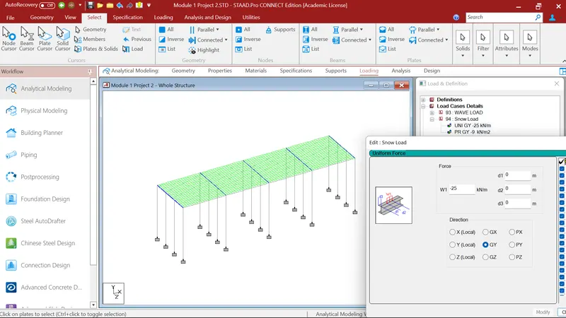
I go to the load case details where I first defined the Snow load. In snow load I go to the member load, In member load I go to uniform force where I first defined the snow load -25kN/m in GY direction which I calculated earlier. After that I select the cross beams in z direction and assigned it to the selected beams.
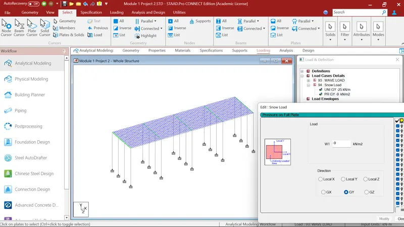
After that I again go to the load case details where I again defined the Snow load. In snow load I go to the plate load, In plate load I go to pressure on full plate where as per IS 875 Part(IV) minimum snow load of 9kN/m2 should be applied to the structure, So I applied in GY direction as W1= -9kN/m2. After that I select the deck slab and assigned it to the selected plates.
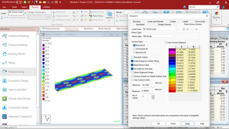
After that I run the analysis command and go to the post processing mode. Where I 1st select the deck slab plates. And checked for the maximun bending moment in Mx direction. Where maximum bending moment in Mx direction is -34.157kN-m/m
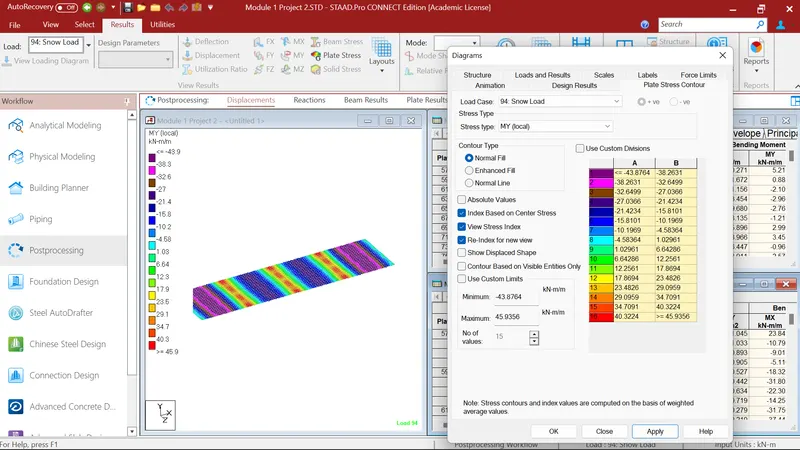
After that I again select the deck slab plates. And checked for the maximun bending moment in MY direction. Where maximum bending moment in MY direction is 45.95kN-m/m.
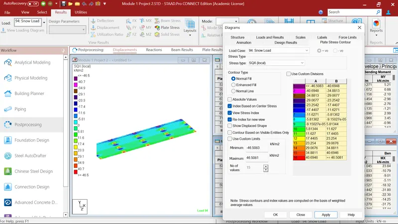
After that I again select the deck slab plates. And checked for the maximun shear force in SQX direction. Where maximun shear force in SQX direction is 46.508kN/m2.
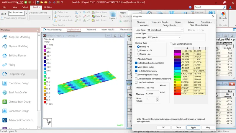
After that I again select the deck slab plates. And checked for the maximun shear force in SQY direction. Where maximun shear force in SQY direction is 63.47kN/m2
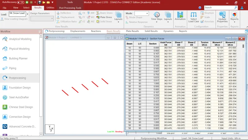
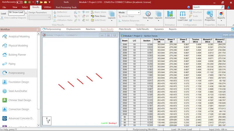
After that I go to the beam result where I select the cross beam element. After that I go to the section forces where i checked for maximun bending moment in MY direction. Where I got maximun bending moment 12.191kN-m in MY direction.
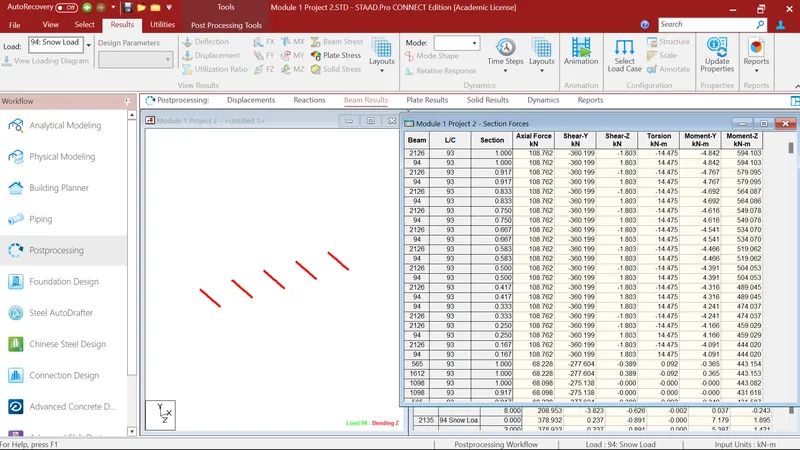
After that I again go to the section forces where i checked for maximun bending moment in MZ direction. Where I got maximun bending moment 594.103kN-m in MZ direction.
After that I again go to the section forces where i checked for maximun shear force in FY direction. Where I got maximun shear force 64.526kN in FY direction.
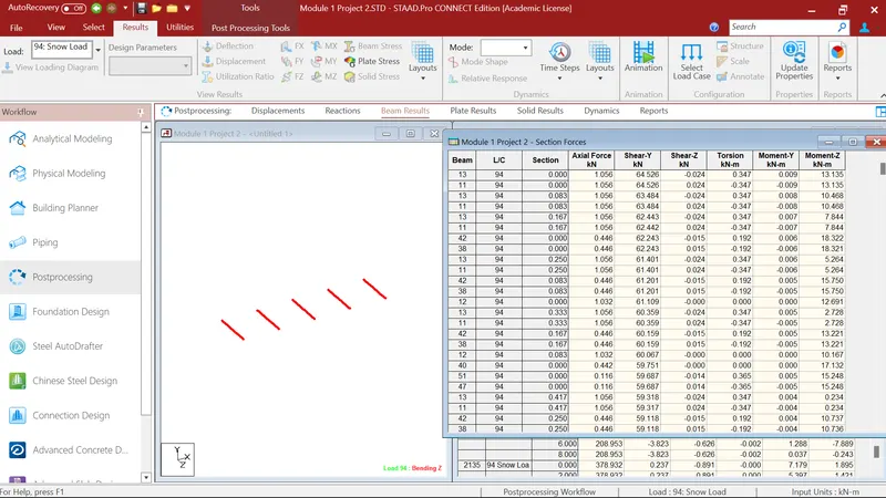
After that I again go to the section forces where i checked for maximun shear force in FZ direction. Where I got maximun shear force 6.867kN in FZ direction.
Temperature Load Calculation:
As per IRC: 6- 2016 clause 215.2 fig 8 & 9.
Maximum temp. in delhi = 47.5 degree
Minimum temp. in delhi = -2.5 degree
Effective temprature difference
= (47.5+(-2.5)/2+10
= 32.5 degree
Stress due to temperature = α x deltaT x E
= 11.27 x 10^(-6) x 32.5 x 5000(40)^(0.5)
= 11.58kN/m2
Max permissible stress = (2/3) x 0.7 x √fck
= 2/3 x 0.7 x (40)^(0.5)
= 2.95kN/m2
Hence, the stresses are restricted to 3 kN/m2.
Positive temprature difference
Temperature at top = 47.5 degrees
Temprature at bottom = (2.1/17.8) x 47.5
= 5.60 degrees
Staad Pro Temperature Load Analysis:
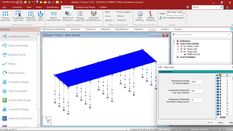
I go to the load case details where I first defined the Temperature load. In Temperature load I go to the Temperature loading, where I gave the value of 32.5 degrees in Temp change for axial alongation which I calulated eariler. And for temp difference from top to bottom I gave 5.6 degrees which I calulated eariler. After that i assigned it to the whole structure by using command assign to view.
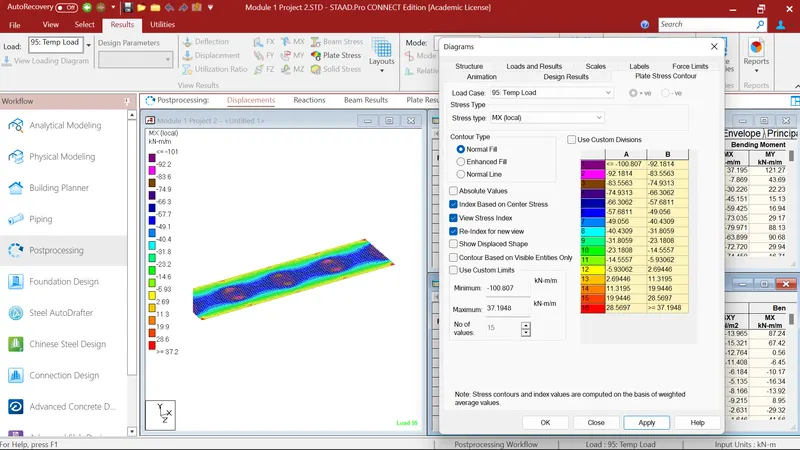
After that I run the analysis command and go to the post processing mode. Where I 1st select the deck slab plates. And checked for the maximun bending moment in Mx direction. Where maximum bending moment in Mx direction is -100.807kN-m/m.
After that I again select the deck slab plates. And checked for the maximun bending moment in MY direction. Where maximum bending moment in MY direction is -222.862kN-m/m.
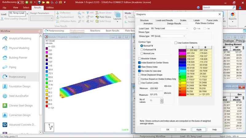
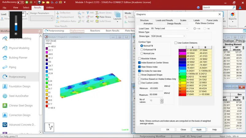
After that I again select the deck slab plates. And checked for the maximun shear force in SQX direction. Where maximun shear force in SQX direction is -65.93kN/m2
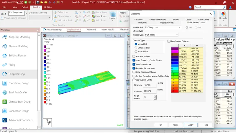
After that I again select the deck slab plates. And checked for the maximun shear force in SQY direction. Where maximun shear force in SQY direction is -137.03kN/m2
After that I go to the beam result where I select the whole beam element. After that I go to the section forces where i checked for maximun bending moment in MY direction. Where I got maximun bending moment 1328.126kN-m in MY direction.
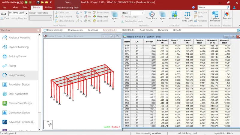
After that I again go to the section forces where i checked for maximun bending moment in MZ direction. Where I got maximun bending moment 594.103kN-m in MZ direction
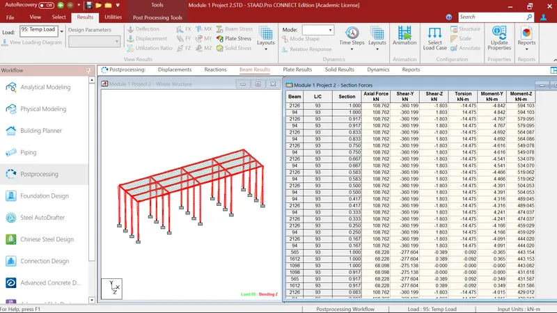
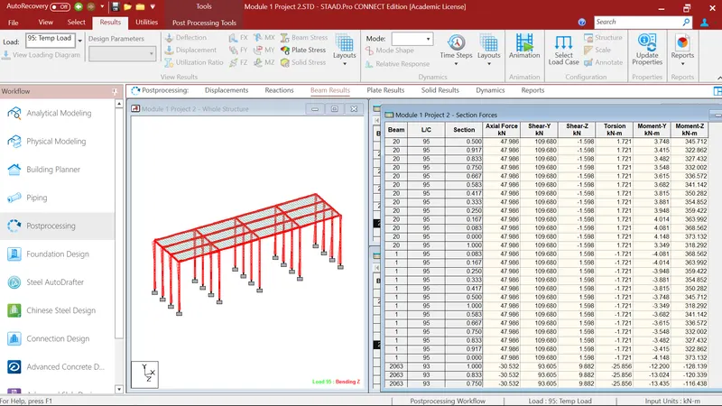
After that I again go to the section forces where i checked for maximun shear force in FY direction. Where I got maximun shear force 109.690kN in FY direction.
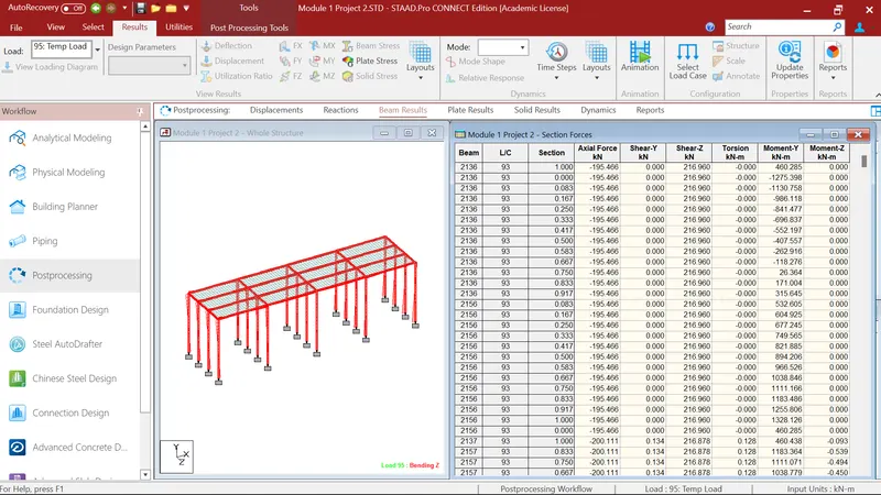
After that I again go to the section forces where i checked for maximun shear force in FZ direction. Where I got maximun shear force 216.960kN in FZ direction.
Barge Impact Load Calculation:
As per IRC : 6, Barge collision Energy KE = 500 x W x Ch x V2
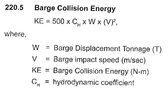
KE = 500 X 25000 X 1.25 X (16.7)^2
KE = 4.35 X 10^9 N-m
Barge Damage Depth
aB = 3100 x ([1 + 1.3 x 10^(-7) x KE]^(0.5)-1)
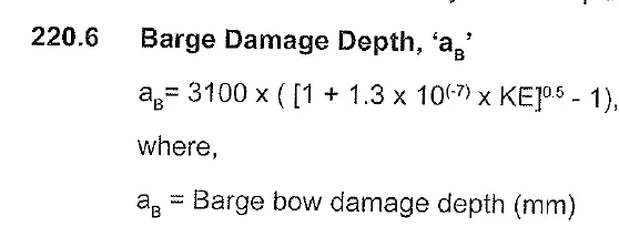
aB = 73783 mm
Barge Collision Impact Force, 'PB'
as per above solution ab > 100mm, So, PB = 6.0 x 10^6 + 1600 x (aB)

PB = 124052800 N = 124052.8kN
Staad Pro Barge Impact Load Analysis:
I go to the load case details where I first defined the Barge Impact Load in +Z Direction. Where in Barge Impact Load I go to the Node loading, where I gave the value of Fz 124052.8 kN which I calulated eariler. And I gave the value of Fz -124052.8 kN for -Z direction. After that i assigned it to the middle node on each span.
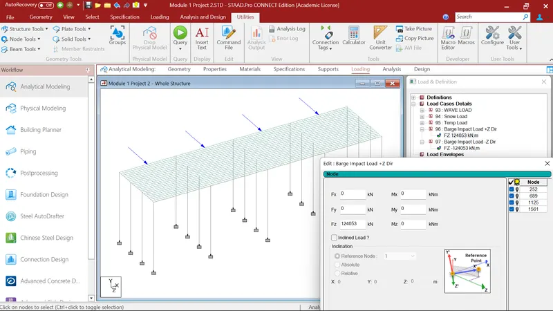
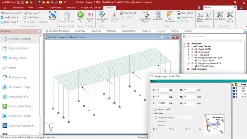
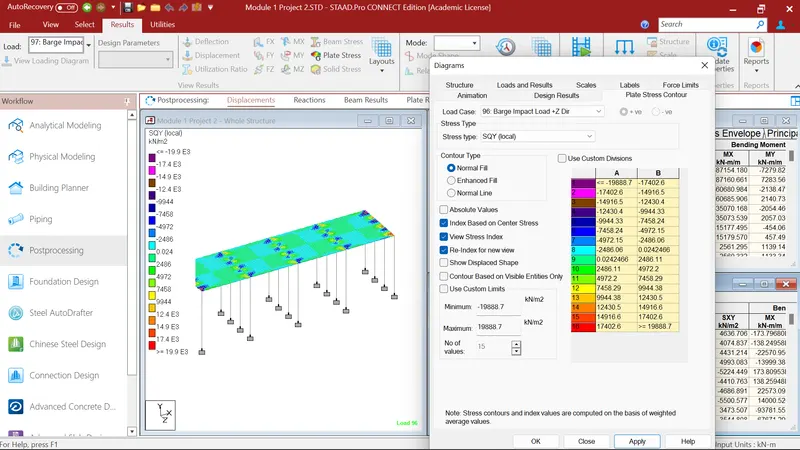
After that I run the analysis command and go to the post processing mode. Where I 1st select the Barge Impact load in +Z direction in deck slab plates. And checked for the maximun bending moment in Mx direction. Where maximum bending moment in Mx direction is 87160.7kN-m/m.
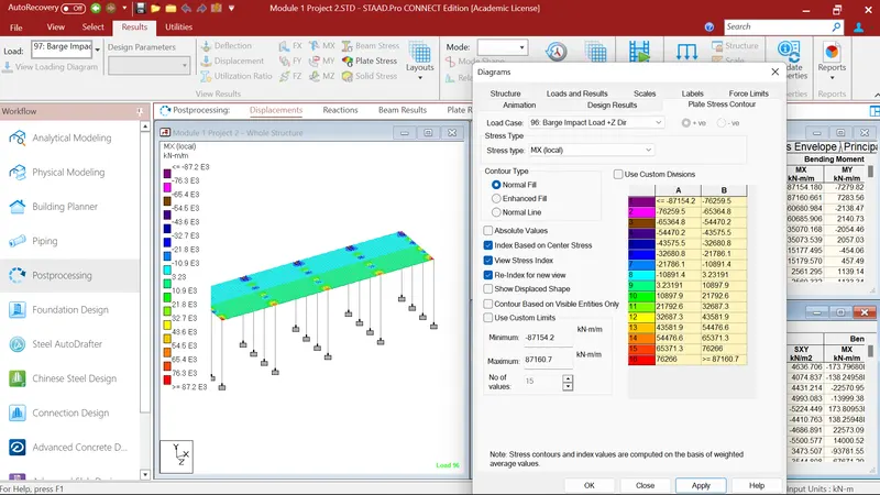
After that I again select the deck slab plates. And checked for the maximun bending moment in MY direction. Where maximum bending moment in MY direction is 7772.68kN-m/m.
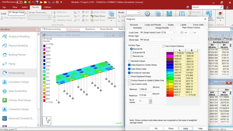
After that I again select the deck slab plates. And checked for the maximun shear force in SQX direction. Where maximun shear force in SQX direction is 29184.7kN/m2.
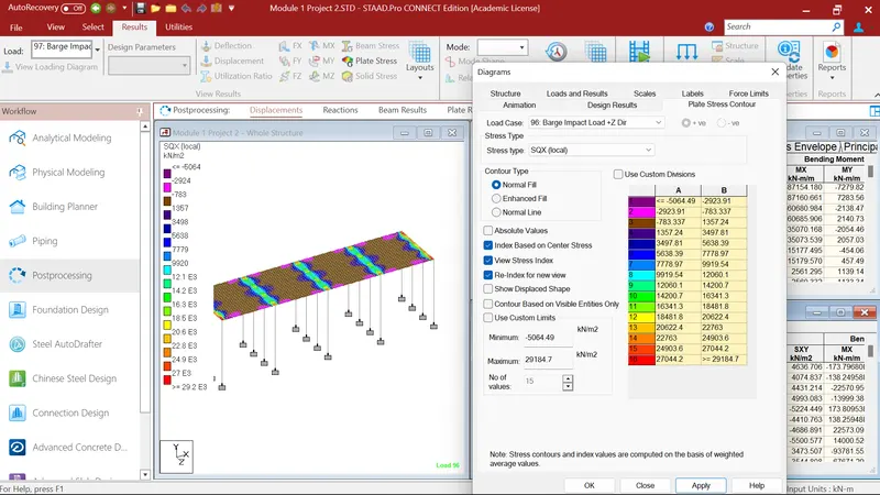
After that I again select the deck slab plates. And checked for the maximun shear force in SQY direction. Where maximun shear force in SQY direction is 19888.7kN/m