Project 2
QUESTION :
Develop general arrangements for the RC office building. Analyze and design the building as per IS standard code in TEKLA STRUCTURAL DESIGNER. Refer to the attached plan and elevation. The building is to be designed for dead, live, wind and seismic loading.
Report of each member to be generated and extract drawings for structural plans, beam reinforcement details from the software.
ANSWER :
AIM: To develop a model as per the given plan and analyze and design the structure.
TOOLS USED :
- Paint.
- Manage property sets.
- Construction levels.
- Grids.
- Columns.
- Beams.
- REports.
- Model report.
- Show report.
- Interactive design.
- Slabs on beams.
- Frames.
- Roof panels.
- Wall panels.
- Loads.
- Load cases.
- Seismic wizard.
PROCEDURE :
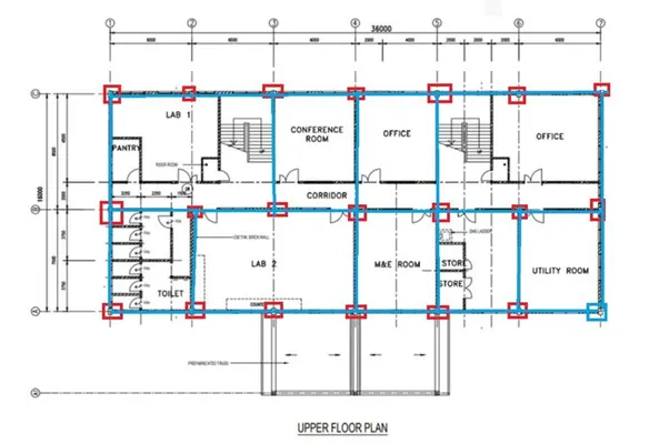
- Take the screenshots of the plan and open them in paint.
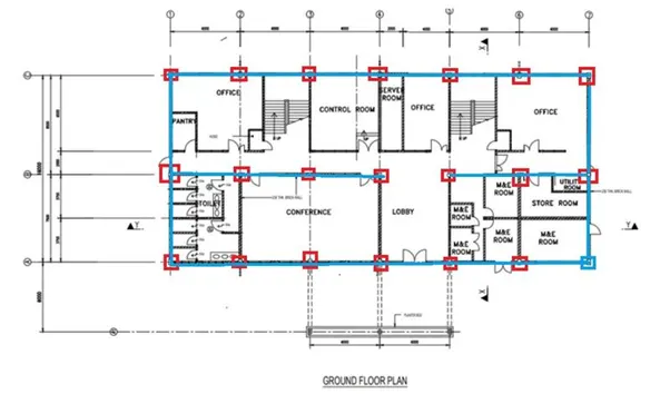
- Draw the positions of columns and beams in paint.
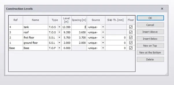
- Open the Tekla file and create the construction levels for the structure according to the plan.
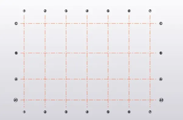
- Construct horizontal and vertical grid lines.
- Select the size of the concrete column section used in the construction as per the requirement.
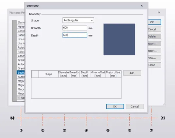
- Go to manage property sets and create members used for the modelling.
- Go to the model tab and insert concrete columns in the structure.
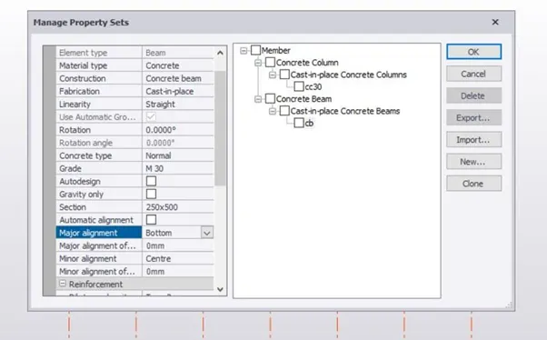
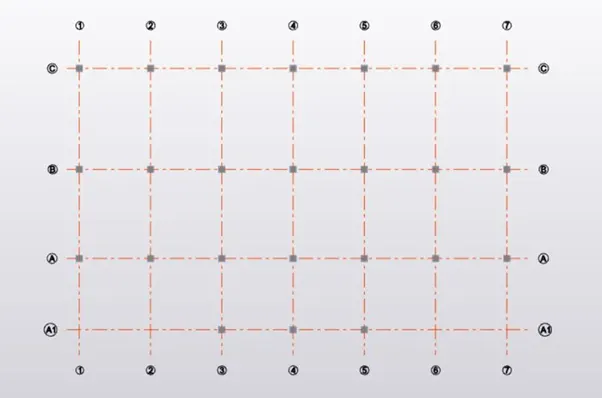
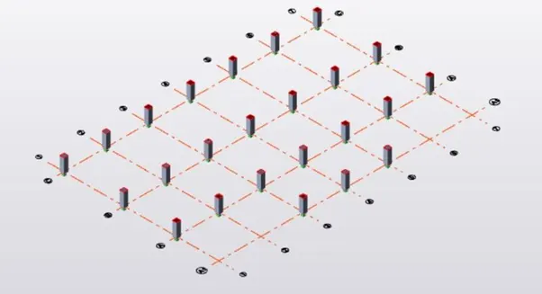
- Go to the model tab and select the beams tool and draw the beams as per the plan.
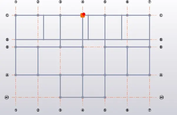
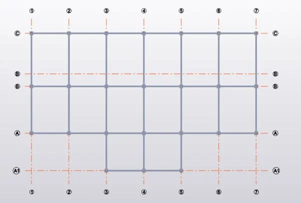
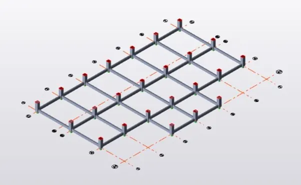
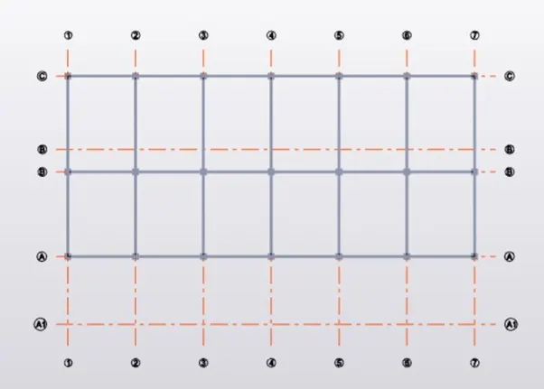
- We can check the structure in 3D for a neat view.
- Repeat the same process for the levels as per the plan.
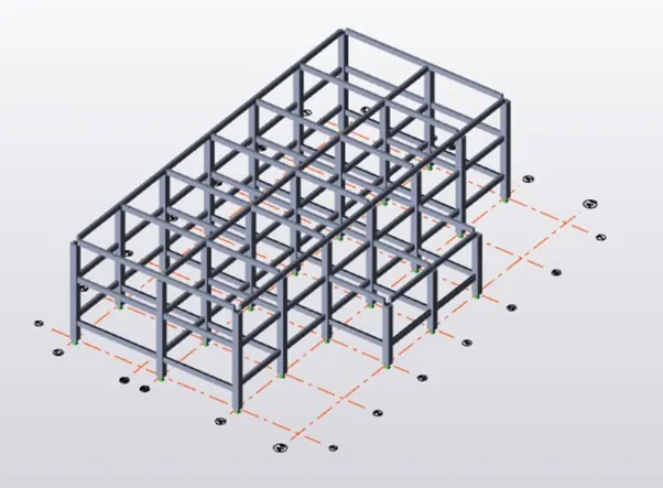
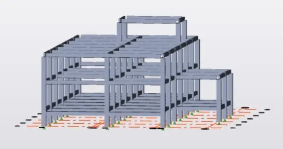
- Select slabs on beams and insert slabs for all the floors, where ever required.
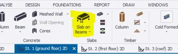
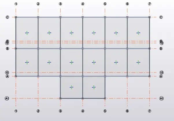
- Go to 3D view to get a clear view of the slabs inserted.
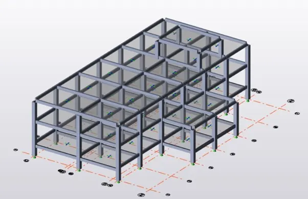
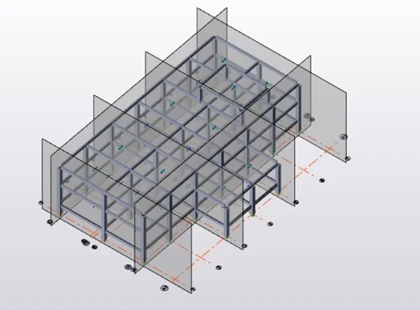
- Insert frames that will be helpful while applying loads on the structure.
- Add wall panels to the structure.
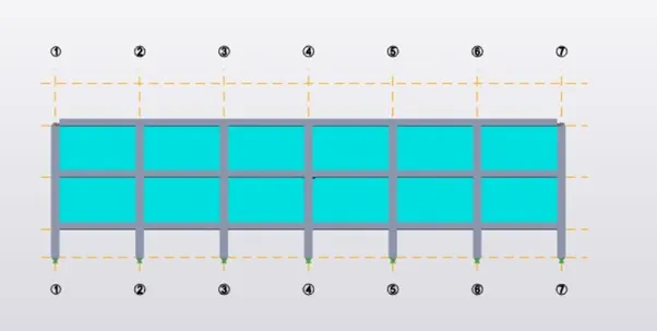
- Repeat the same step for all the walls.
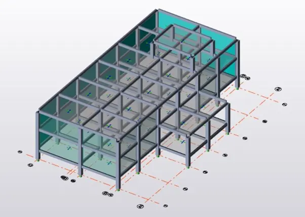
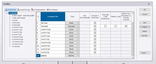
- Go to loads and create new load cases.
- Add the dead load on the beams.
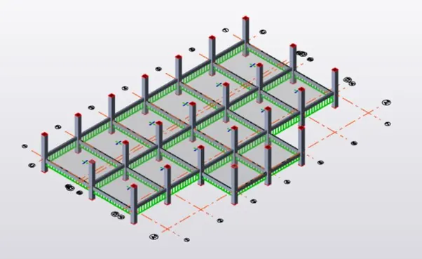
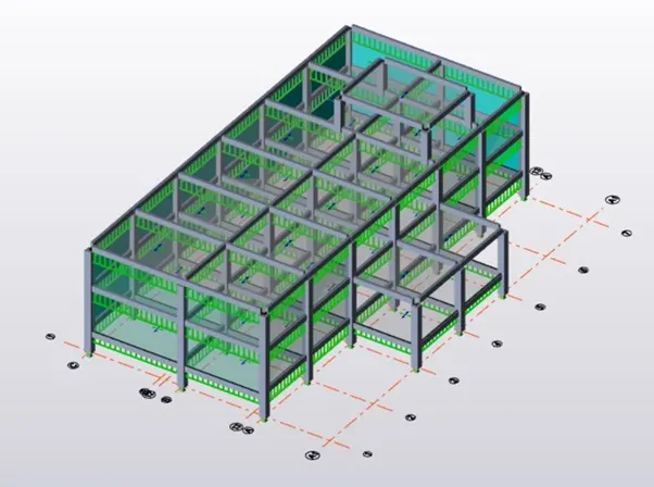
- Add the dead loads on the slabs.
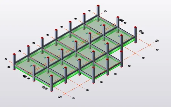
- Repeat the same step for all the floors.
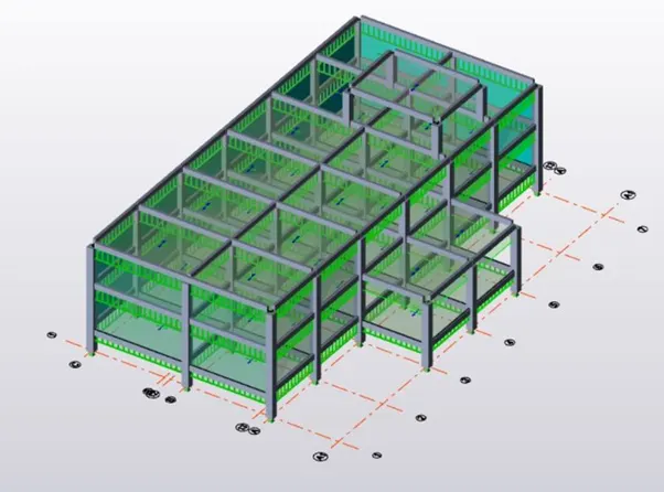
- Add live load on the structure for all the floors.
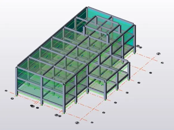
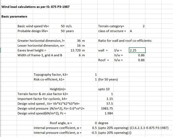
- Do the wind load calculation for all the sides for both X and Y ( including both +Cpi and -Cpi values).
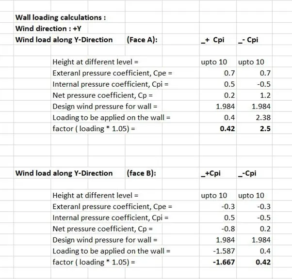
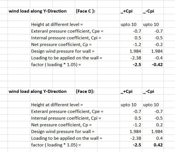
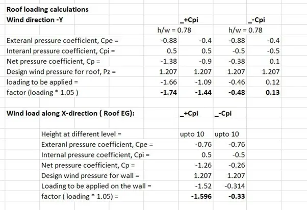
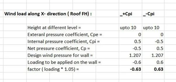
- Start applying the wind loads on the structure.
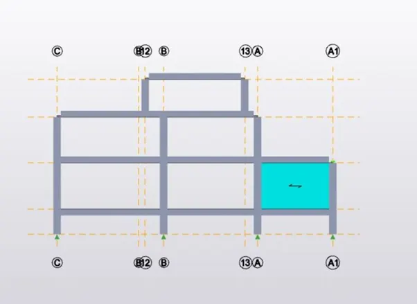
- Repeat the same process for all the sides.
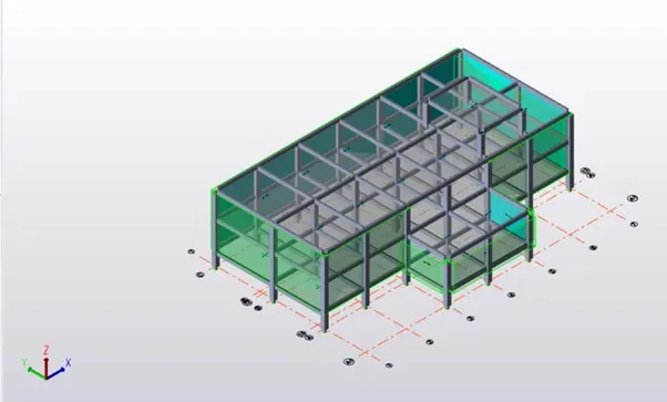
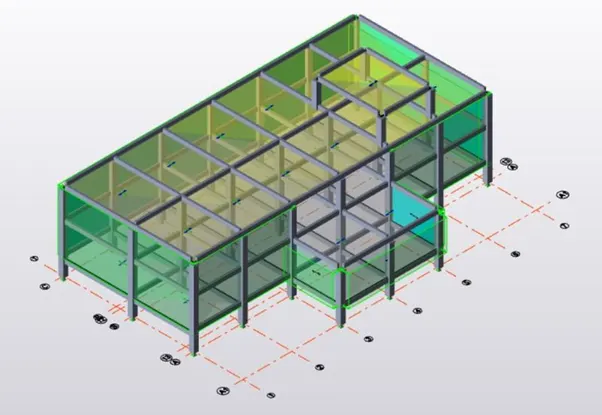
- Add roof panels to the structure and also add roof load.
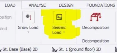
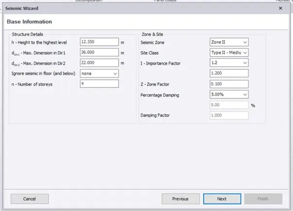
- Apply seismic load on the structure by selecting seismic wizard.
- A seismic wizard dialogue box appears.
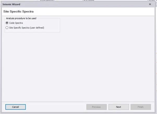
- Enter the required values required for seismic load calculation.
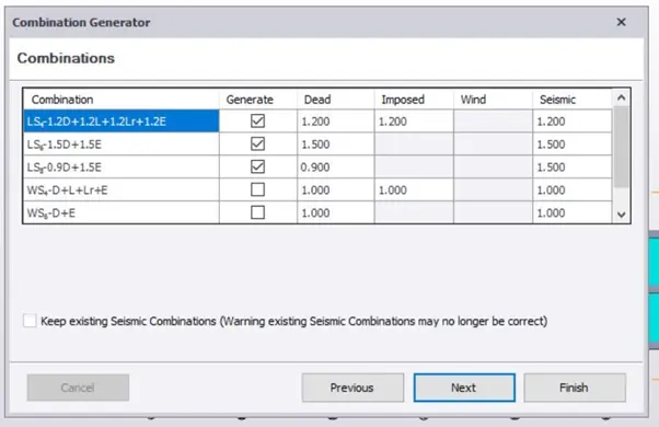
- Add loads that will be applied are visible now.
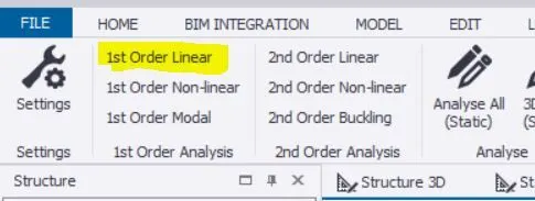
- Analyze the structure by selecting the 1st order Linear option.
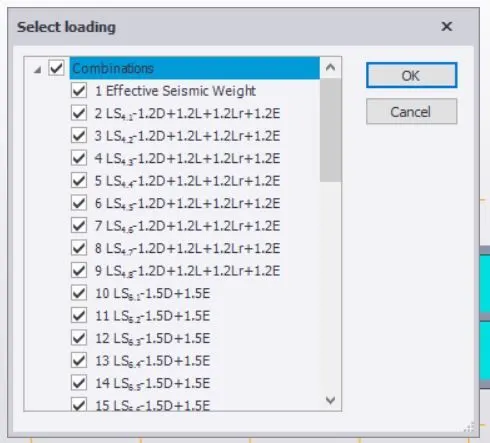
- Select all the loadings required for the analysis.
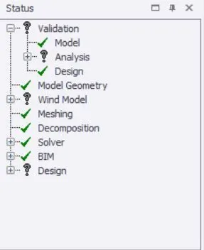
- Validate the model to check that there are no errors.
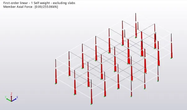
- Check the axial load diagram.
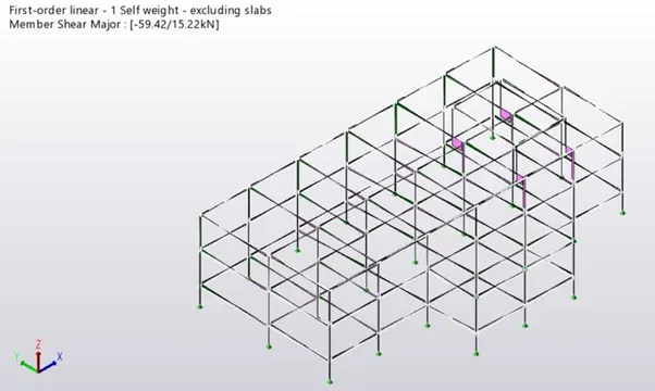
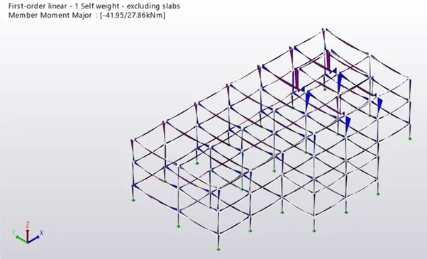
- Check the shear force and bending moment diagram.
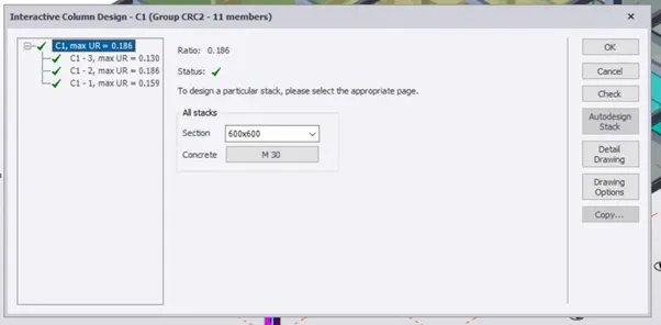
- Check each column and perform interactive design.
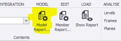
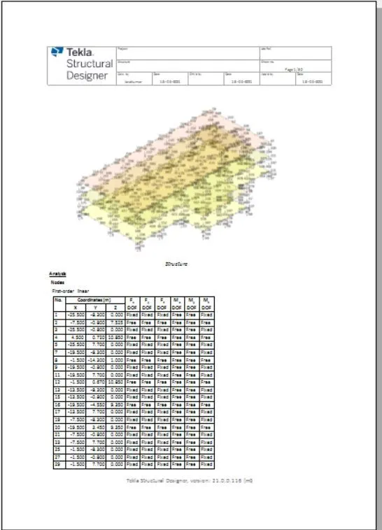
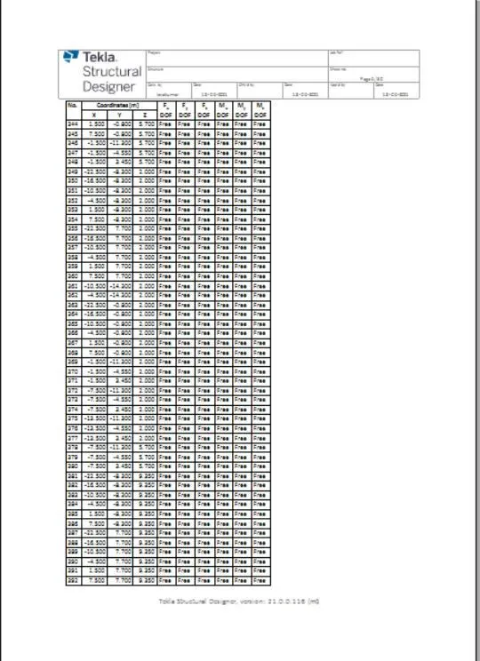
- Now we can model the structure by pressing on the model report to obtain the reports.
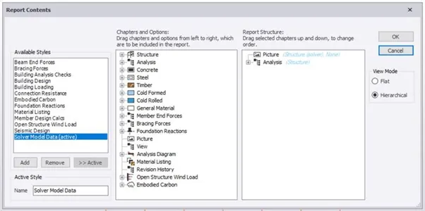
- Select what all reports we need.
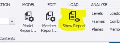
- Now for seeing the reports we have to press on the show reports option.
RESULT :
With the above steps, we can design and model the structure as per the given plan. We can add loads ( dead, live, wind and seismic) to the structure and analyze the structure.