Project 2
Ans
Aim and Introduction:-
- The primary aim of this challenge is to arrive at optimum bearing articulation using two bearing and one bearing system.
- To model the bridge as per the given dimension and apply all the load combinations on it. Then to analyze the results.
- The substructure such as pier need to be checked by modelling the structure in ASBD software and to check the efficient section by optimiziing the size of the section.
- Then to check all the needful checks as per the relevant code IIRC 112 and to the present the detailing as per the calculation.
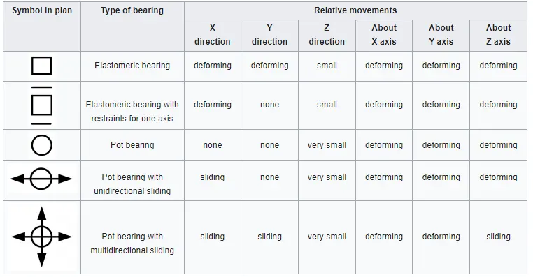
Bearings
Basically bearings are provided to trasfer the load of the super structure to the sub structure. It resisit the lateral and transverse movement of the super structure.
Movements can be either permanent (irreversible) or transient (reversible).
Generally, the structure will rotate about longitudinal and transverse axes at its supports and these rotations must either be accommodated in the bearings or the bearings must be designed to resist them (in which case the effects on the structure must also be considered). In some cases, there is also a rotation about a vertical axis (associated with plan bending of the structure) but this is usually small in magnitude.
Horizontal displacements at supports arise both from an overall change in length of the structure and due to bending in a vertical plane (since the centroidal axes are above the levels of the supports). Since it is necessary to resist horizontal forces at at least one position, it is usual to do so by preventing horizontal displacement at that position; this means that horizontal displacements at other positions are due to the expansion/contraction of the length from the fixed bearings and to the (vectorial) sum of the movements due to bending rotation.
The following recommendations relate to the articulation arrangements for typical highway bridges.
As bearings and the expansion joints introduce a maintenance liability, it is good practice to limit the number of bearings required and to minimise the movement to be accommodated by an expansion joint. Spans should be arranged so as to avoid uplift at bearings positions (it is a very complex and costly matter to provide restraint against uplift in a bearing), particularly when dealing with skewed structures.
The designer should avoid locking in forces that would hinder bearing replacement. Restraint against longitudinal forces should be provided at one support, with guided restraints aligned to allow movement at the other supports. Similarly, restraint against transverse forces should be provided at only one bearings at each support. The construction sequence of the structure should also be considered, to establish the permanent displacements.
The articulation scheme that the designer chooses should be shown on the drawings and will form the basis of a bearing schedule.
- Bearing articulation using 2 bearings:-
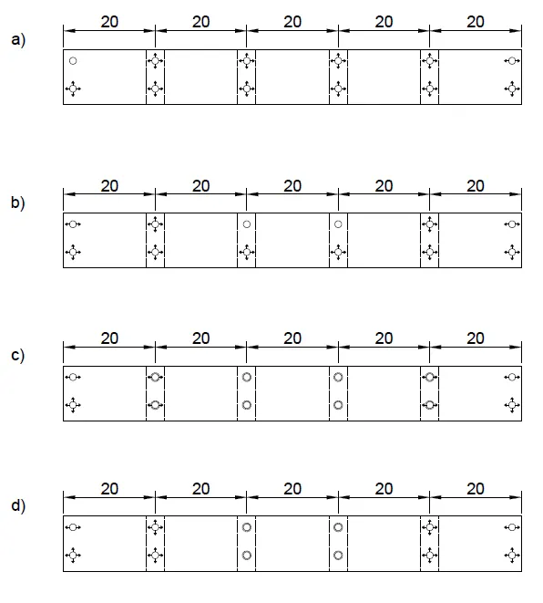
- The superstructure is of 5 span bridge with length of spans as 20m each.
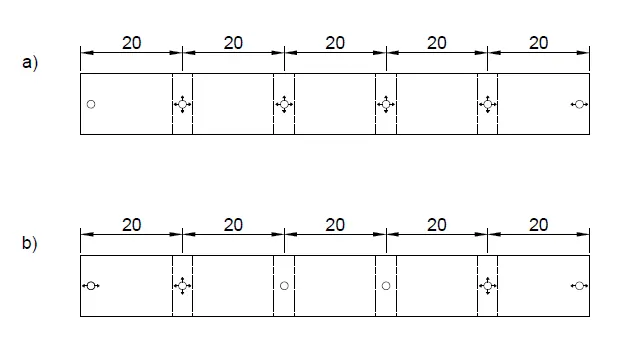
- The articulation for the bearing of the continues structure is as follows.
- There are four possible arrangements.
- a) may be used if longitudinal loads can be resisted at the abutment
- this leads to the largest bearing movements (at the far end)
- intermediate guided bearing(s) are needed if the deck cannot span laterally between abutments
b) reduces the maximum movement compared to (a)
- a strong pier is required at the fixed bearing to resist the longitudinal loads.
- the deck acts in plan as a two-span beam.
c) If the pier columns are flexible laterally, each bearing may be guided; if the central columns are strong enough, they may provide the longitudinal restraint, as in (b).
d) If the central piers are tall and flexible, they may share in providing longitudinal restraint.
Note that in (c) and (d) the columns are restrained transversely at the top by the deck.
- The articulation for the bearing of the continues structure is as follows.
- Bearing articulation using 1 bearings:-
- a) may be used if longitudinal loads can be resisted at the abutment
- b) reduced maximum movement
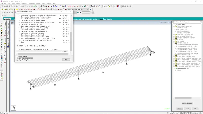
- STAAD Model
- The nodes for the pier has been created.
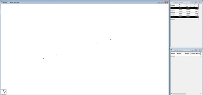
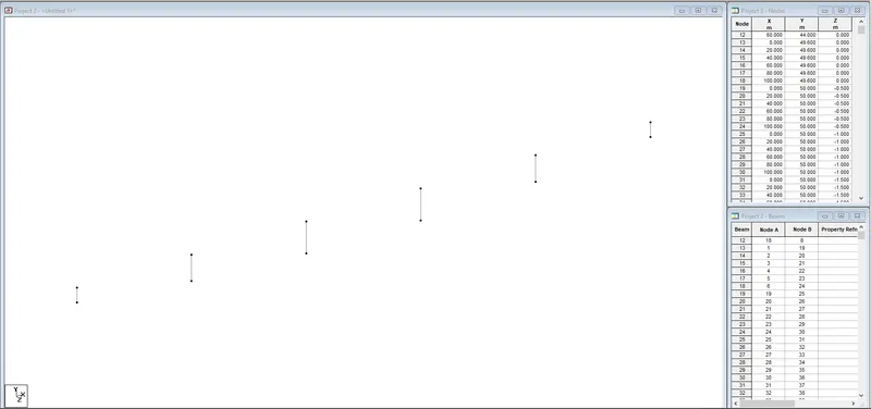
- the piers and abutments has been created as per the given dimension.
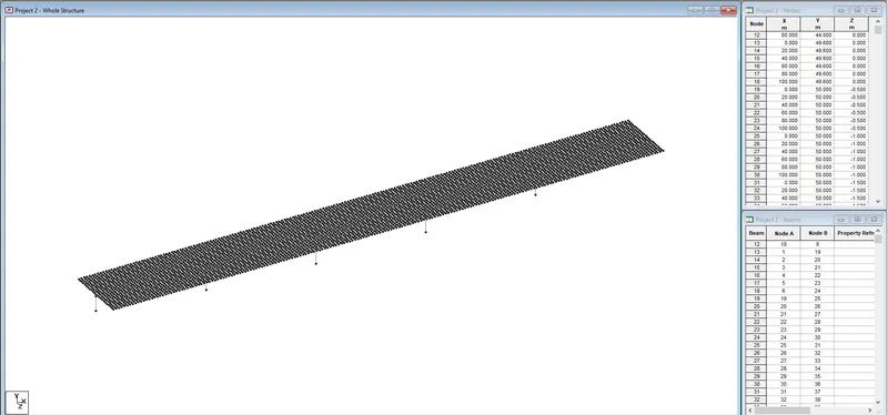
- The Deck has been created.
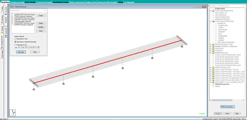
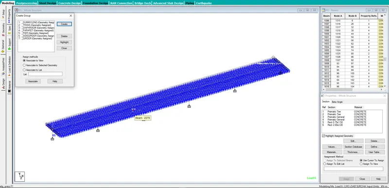
- Groups has been assigned.
- Properties has been created and assigned.
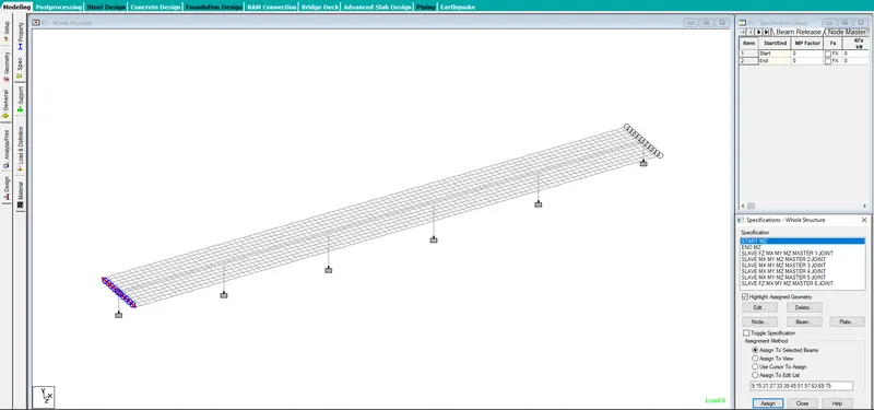
- Master Slave for different nodes has been assigned.
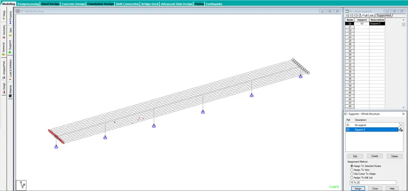
- Fixed supports has been assigned to the model.
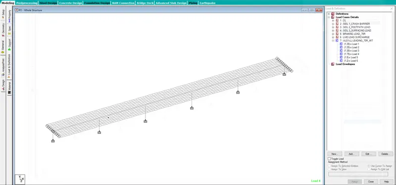
- Different load criterias has been calculated and assigned to the structure.
- The model is being analyzed and results as 0 error.
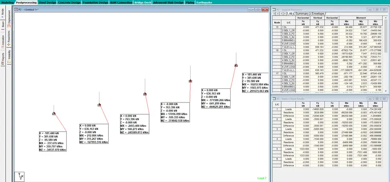
- RESULT & OUTPUT
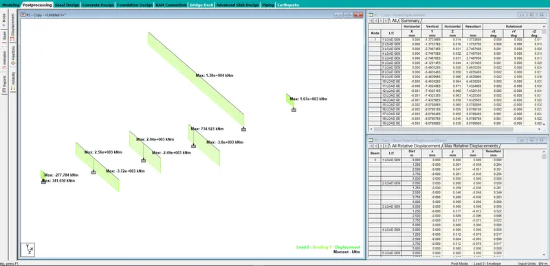
- Max BM Mz for the normal load case
- Max BM My for the normal load case
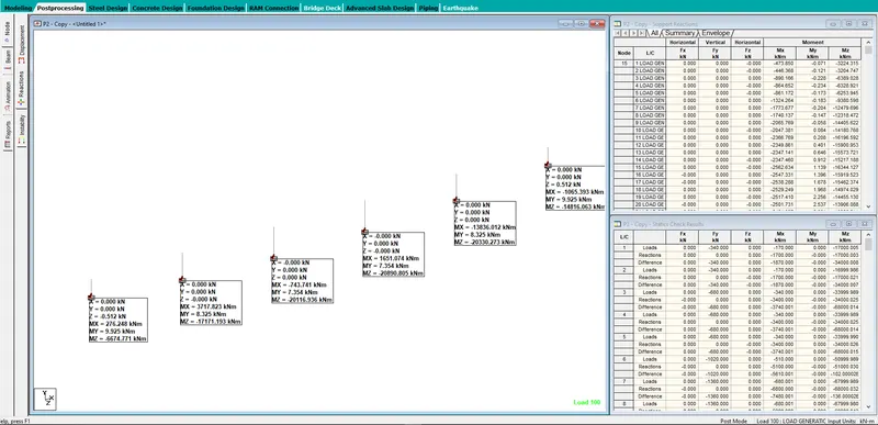
- The axial force
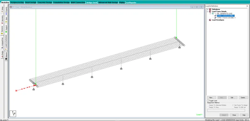
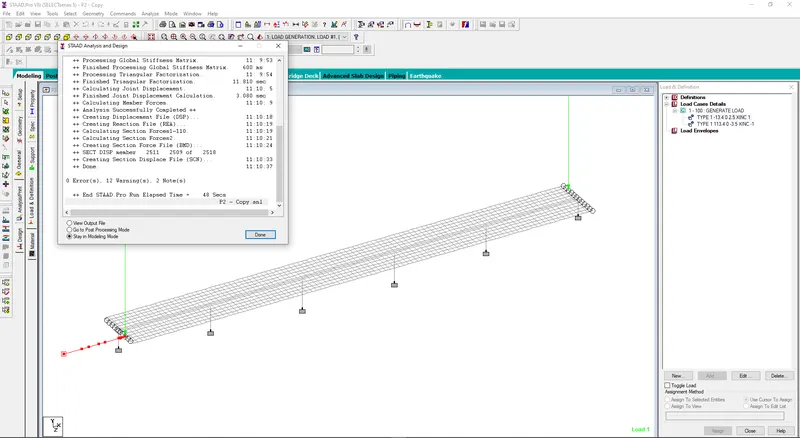
- Another Model has been created to apply only live load i.e. vehicular load.
- Generating loads for moving loads.
- The model is being analyzed and results as 0 error.
- RESULT & OUTPUT
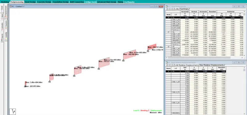
- Max BM Mz for the vehicular load case
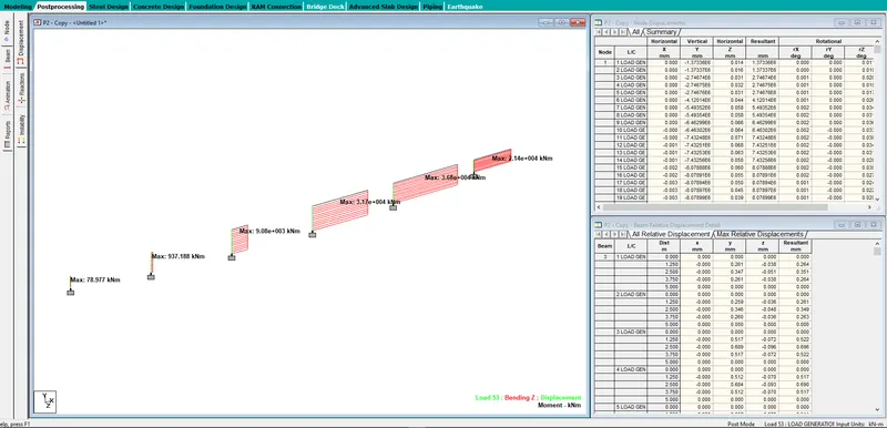
- Max BM My for the live load case.
- The axial force
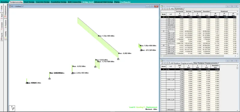
| Load Combination (Normal Case) | Live Load | Live Load | |||||||||||
| Load Case | Structure | Axial Force(KN) | Bending Moment (KNm) (Longitudinal Mz) | Bending Moment (KNm) (Transverse My) | Shear Force (KN) | Axial Force(KN) | Bending Moment (KNm) (Longitudinal Mz) | Bending Moment (KNm) (Transverse My) | Shear Force (KN) | Axial Force(KN) | Bending Moment (KNm) (Longitudinal Mz) | Bending Moment (KNm) (Transverse My) | Shear Force (KN) |
| ULS1-LL LEADING_70R_WT | Pier | 764 | 445000 | 172000 | 2230 | 764 | 55200 | 1920 | 2877 | 1528 | 500200 | 173920 | 5107 |
Design of Fixed Rectangular column using ASBD software
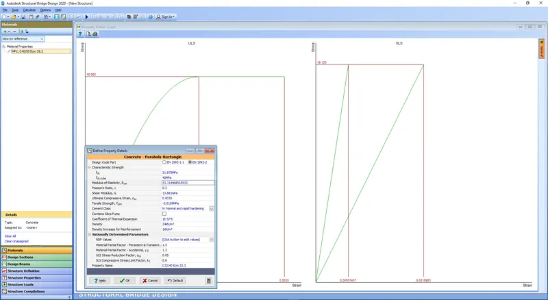
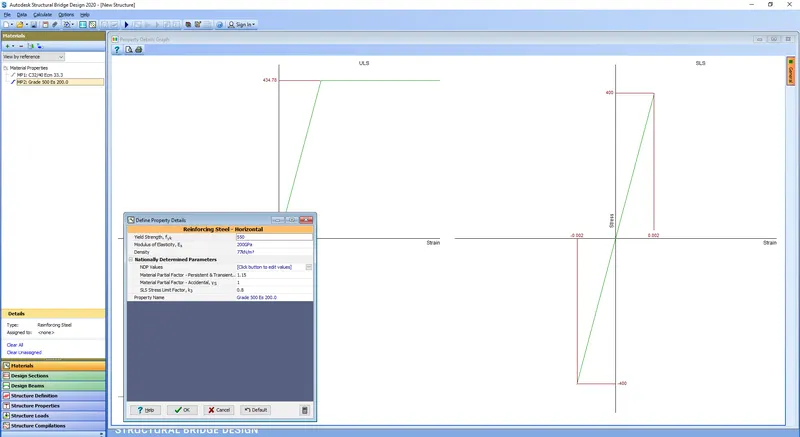
First of all defining the material properties in ASBD software.
- Concrete Properties- Taking Characterstic Strength as 40MPa
- Steel Properties - Taking Characterstic Strength as 550MPa
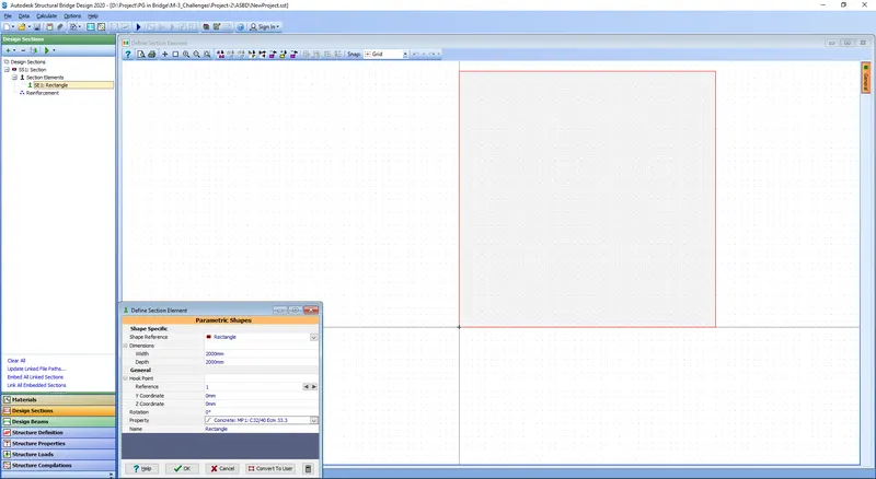
- Defining Section properties as Pier size - 2m x 2m
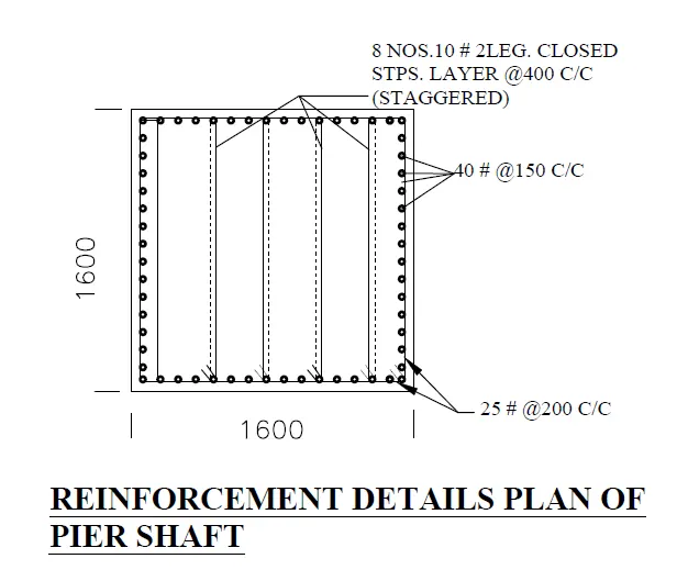
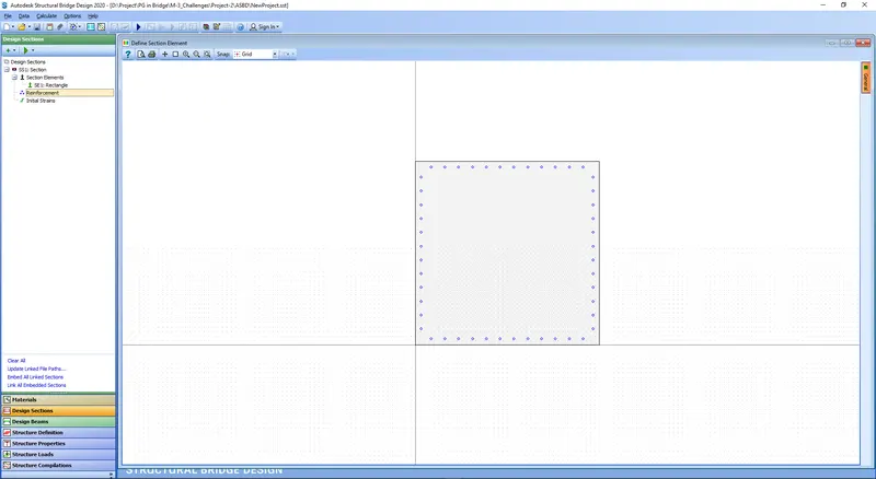
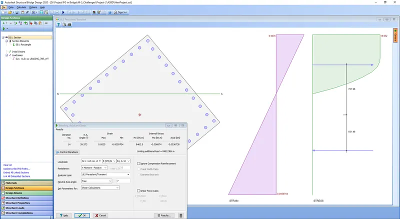
- Providing reinforcement of 32 mm dia at 150 mm spacing in all the faces with 50 mm cover.
- Defing the load details as per the staad model.
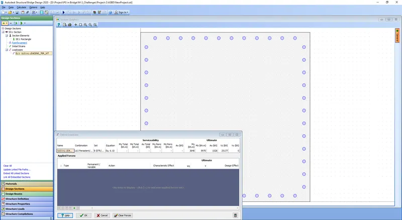
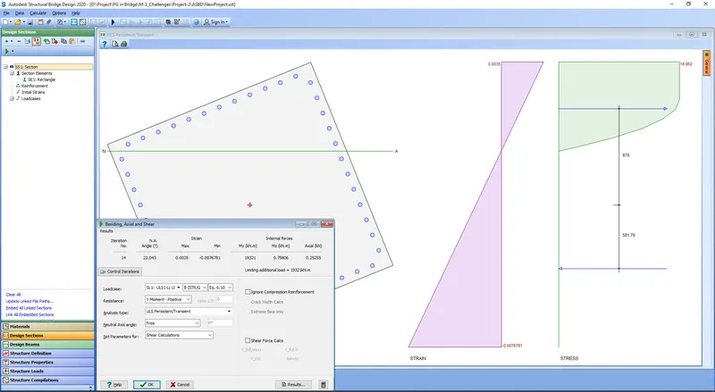
- The section is safe.
- Again considering & optimizing the section to 1.6m x 1.6m. Then also the structure is safe.
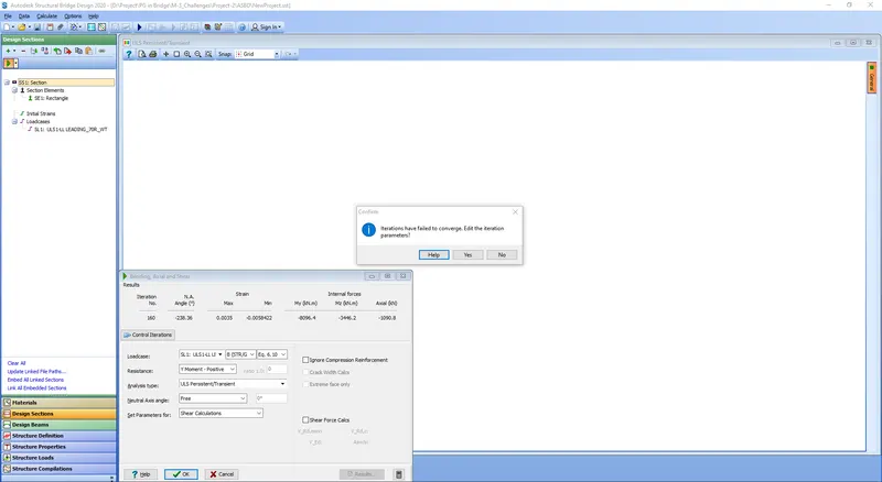
- Again considering & optimizing the section to 1.2m x 1.2m and the structure is not safe.
- So the size of the pier as 1.6m x 1.6m has been taken.
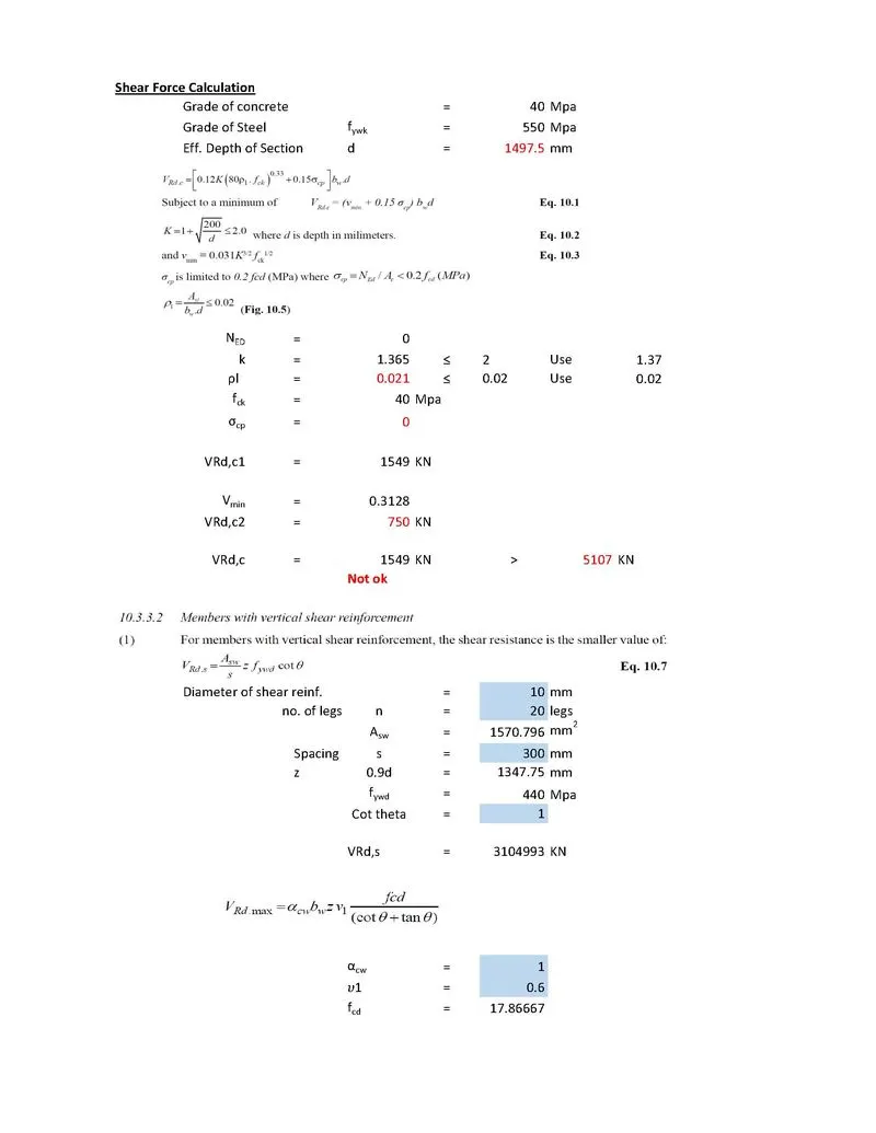
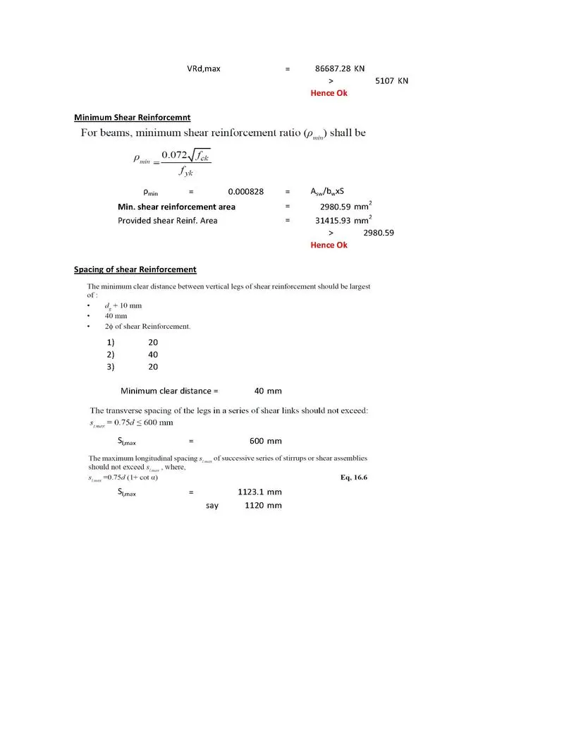
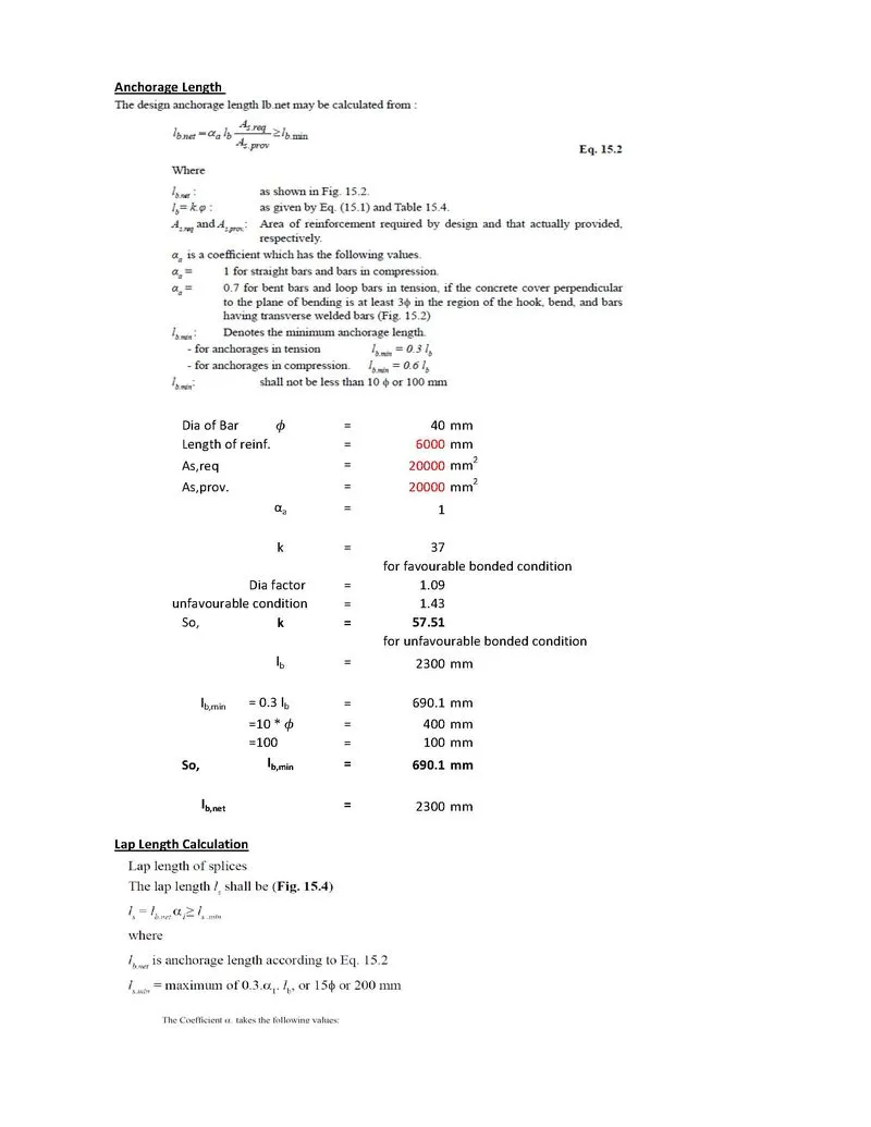
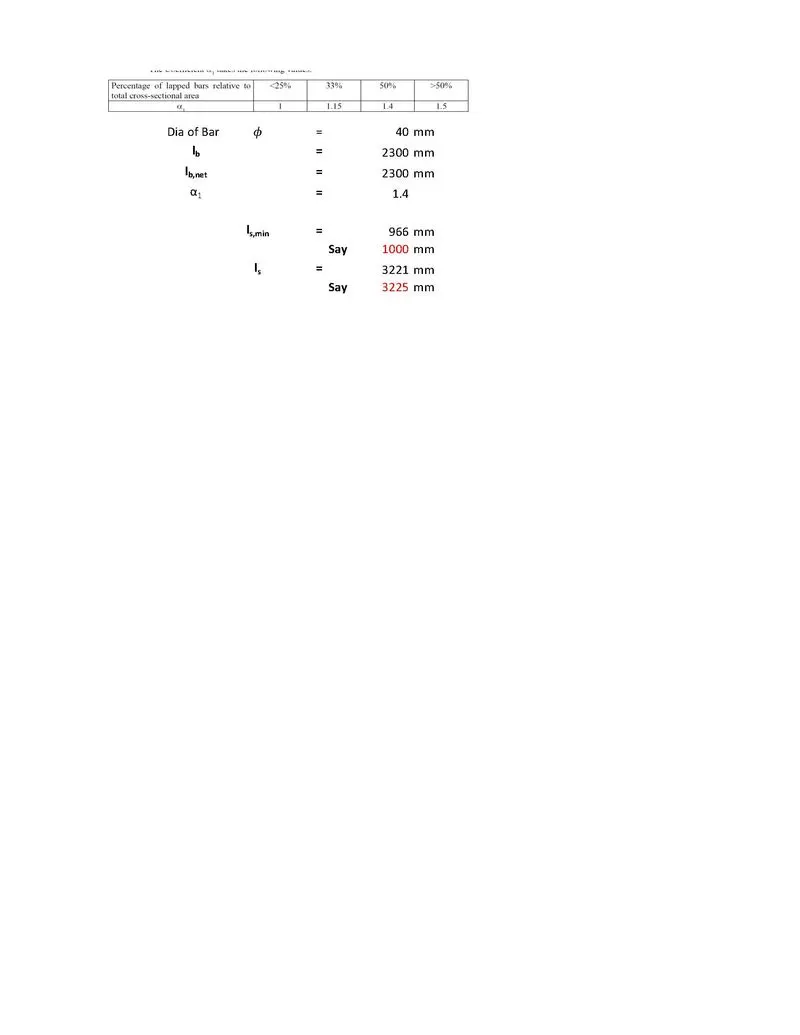
Details Claculations & Checks
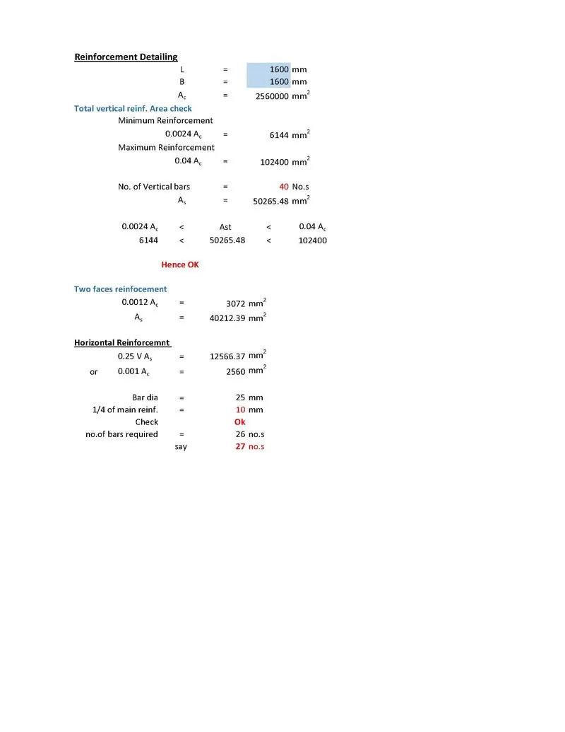
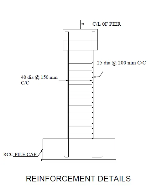
- Reinforcement Detailing
- The reinforcement detailing of the pier is as below.