Project 2
Using MATLAB/simulink and the drive cycle from the attached excel sheet, find-
- The max heat generation of the battery
- The SOC of the battery at 2 *104second of the battery operation
| Time | Time Step | Battery Current |
| 00:00.4 | 0.1 | -0.9632 |
| 00:00.5 | 0.2 | -0.952 |
| 00:00.6 | 0.3 | -0.9072 |
| 00:00.7 | 0.4 | -0.9632 |
| 00:00.8 | 0.5 | -1.0304 |
| 00:00.9 | 0.6 | -0.9632 |
| 00:01.0 | 0.7 | -1.0304 |
| 00:01.1 | 0.8 | -1.008 |
| 00:01.2 | 0.9 | -0.9856 |
| 00:01.3 | 1 | -0.9632 |
| 00:01.4 | 1.1 | -0.9184 |
| 00:01.5 | 1.2 | -0.9296 |
| 00:01.6 | 1.3 | -0.9296 |
| 00:01.7 | 1.4 | -0.9296 |
| 00:01.8 | 1.5 | -0.9184 |
| 00:01.9 | 1.6 | -0.9408 |
| 00:02.0 | 1.7 | -0.896 |
| 00:02.1 | 1.8 | -0.9072 |
| 00:02.2 | 1.9 | -0.9072 |
| 00:02.3 | 2 | -0.9408 |
| 00:02.4 | 2.1 | -0.9296 |
| 00:02.5 | 2.2 | -0.9296 |
| 00:02.6 | 2.3 | -0.9968 |
| 00:02.7 | 2.4 | -0.9968 |
| 00:02.8 | 2.5 | -0.9408 |
| 00:02.9 | 2.6 | -0.9408 |
| Battery resistance | 2 milli ohm |
Consider the battery resistance is 0.5 mOhm, delta time is 0.1 and entropic factor is 2
MATLAB code
Given data is imported to matlab workspace and saved in .mat file. Later it is imported to code.
clc
clear
load("p2data.mat")%loading given data to workspace
r=2e-3;%battery internal resistance
t=pdata.Time;
i=pdata.BatteryCurrent;
tavg=mean(t);%average time
imax=max(i);%max current
h=(imax^2)*r*tavg;%max heat
ef=2;%entropy factor
ht=h+ef*h%total max heat
Output
ht =

   9.1989e-08
SOC of battery
Simulink model is developed for this
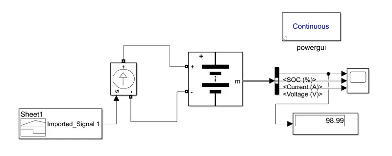
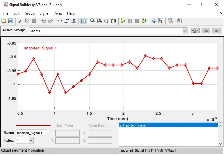
with the given data, a custom signal is generated and fed to controlled current souce. It looks as shown below.
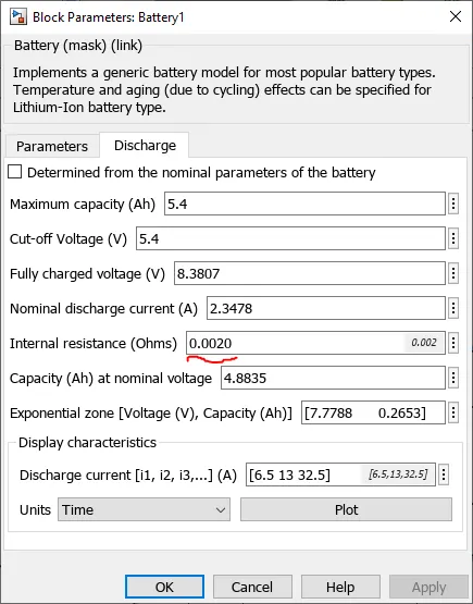
Battery parameters are
Output is obtained as shown below
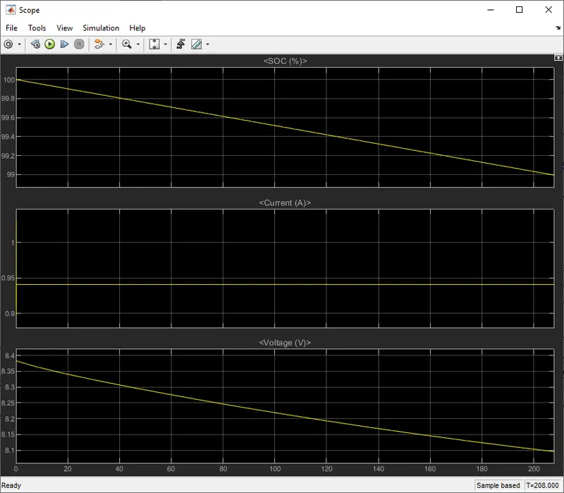
From the results, we can see that SOC at end of 2*104 secs is 98.99 %