PROJECT-2_TAIL GATE WIRING HARNESS ROUTING
AUTOMOTIVE WIRING HARNESS PROJECT 2
WIRING HARENESS ROUTING FOR TAIL GATE
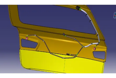
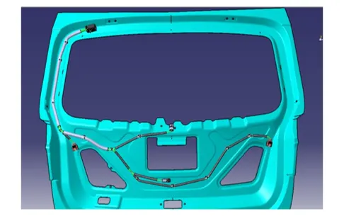
PROCEDURES AND STEP FOLLOWED FOR WIRING HARNESS ROUTING
- Created new product file and named it as “BACK DOOR WIRING HARNESS CONTEXT”.
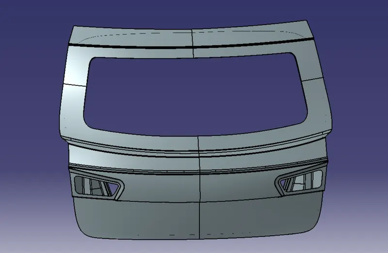
- In that product I have opened the CAD file given for the Tail gate.
- Created another product file inside the wiring harness context assembly file.
- And named “GEOMETRICAL HARNESS BUNDLE BACKDOOR”
- I have made ready all the required connector, Clips, Clamps and protective CAD Data.
- Each components defined electrically by giving respective features.
- Created catalogue documents for particular groups.
- After creating the catalogues, added required connectors and clips from the catalogue browser.
- Using manipulation tool placed all the connectors and clips as required.
- Now for starting the routing first electrically defined the geometrical bundle assembly file using the command Geometrical Bundle.
- That leads to create new multi-blanchable part file inside the GEOMETRICAL HARNESS BUNDLE BACKDOOR.
- Then click on the multi-branchable command led to wiring harness installation work bench from there Using branch definition command started the routing.
- Given all the required parameters like wire radius, bending radius, slack and route definition.
- Created Branch points for adding branches on required positions.
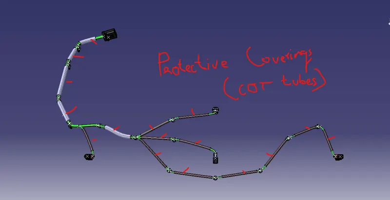
- After well completion of all the connection routing added protective coverings for the wires.
Connectors and Clips used:
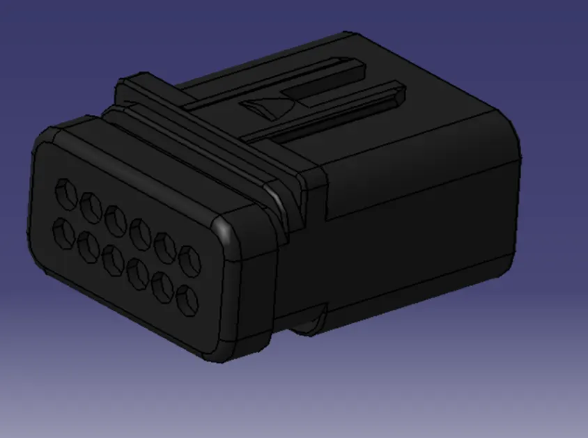
Figure a: 12 pole connector
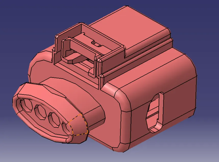
Figure b: 4-pole connector
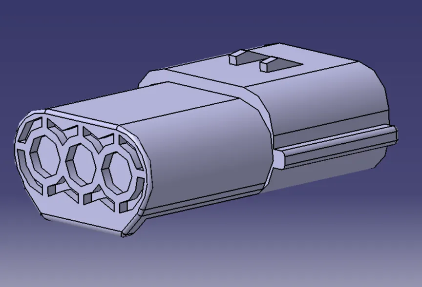
Figure c: 3-pole connector
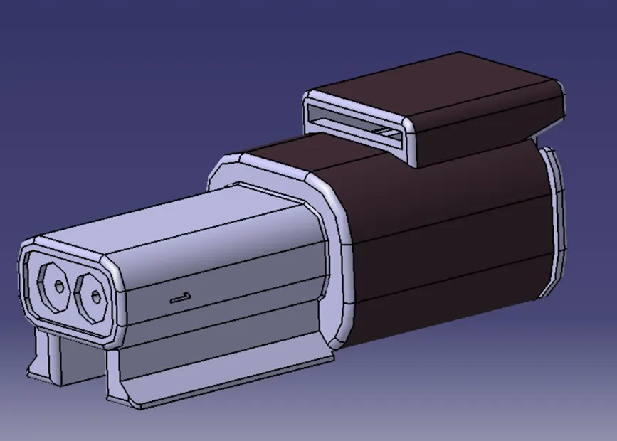
Figure d: 2-pole connector
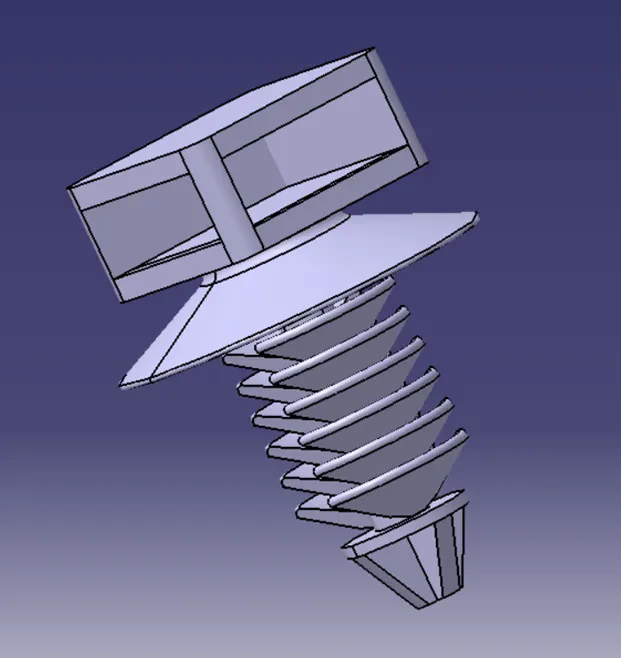
Figure e: Fir Tree clip
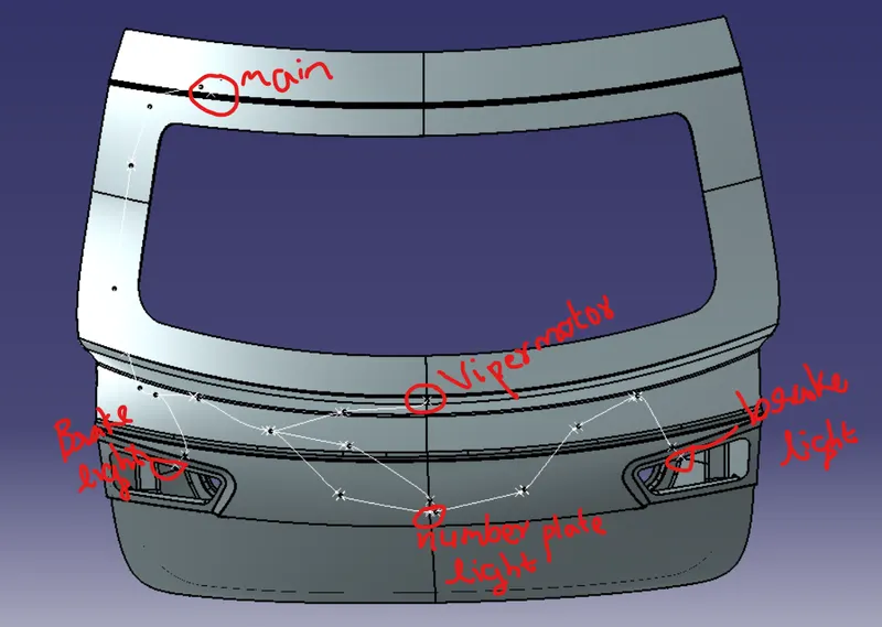
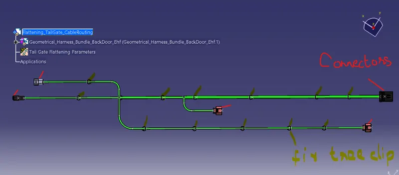
In the below figure red marked are connectors and green marked are fir tree clips
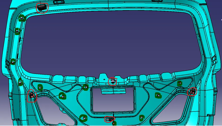
Figure f:Positions of connectors and pins
Branch definition is shown in below figure and the parameters like bend radius, diameter of bundle and slack% is given.
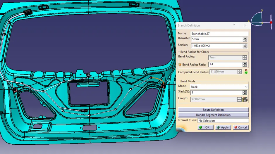
Figure g:Branch definition
Route Definition tab is shown in below figure, here the routing is done between the red marked clip and green marked connector.
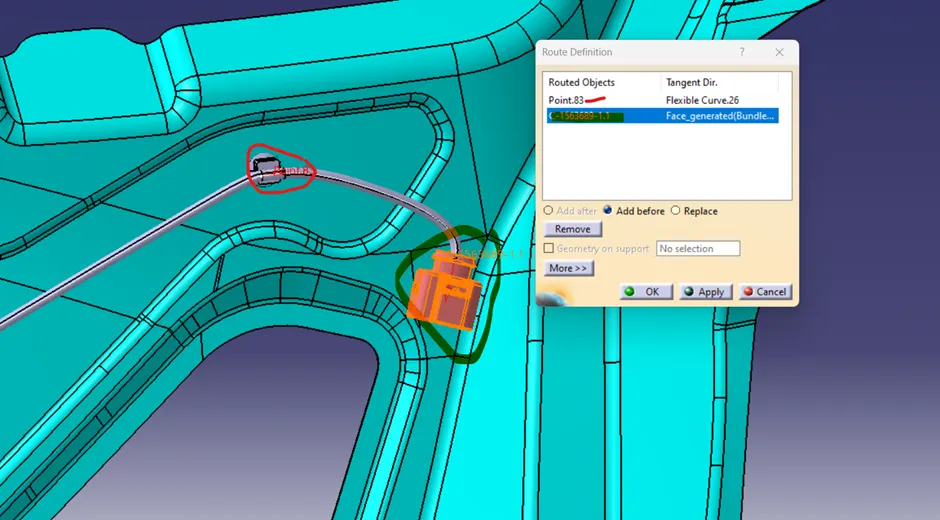
Figure h:Route Definition
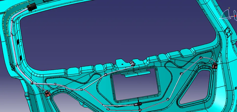
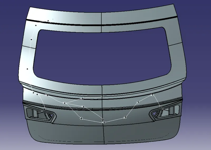
Figure i: Complete routing
Below figure showing the details about adding of protective coverings for the bundle.
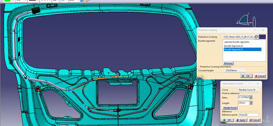
Figure j: After adding protective coverings.
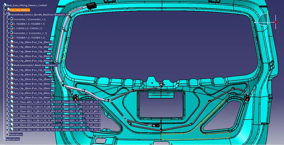
Figure k: Completed routing with expanded tree structure
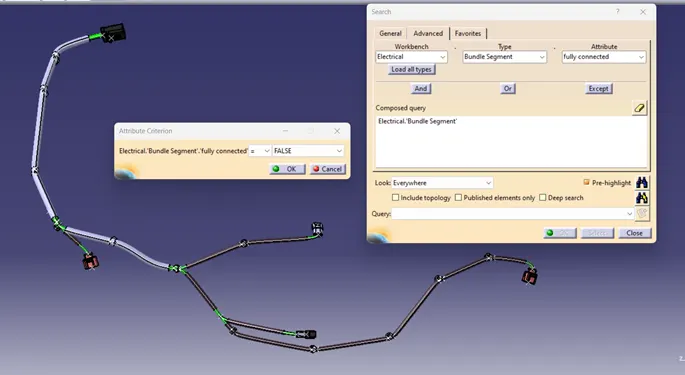
Figure l:Bundle connectivity checking
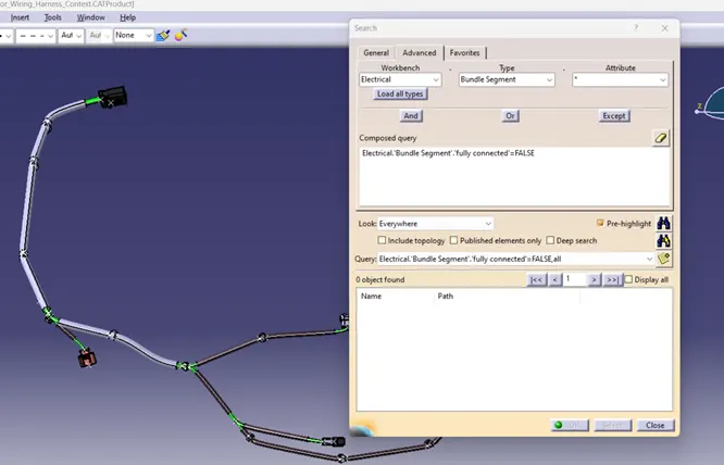
Figure m:Result " When query is fully connectd" -false
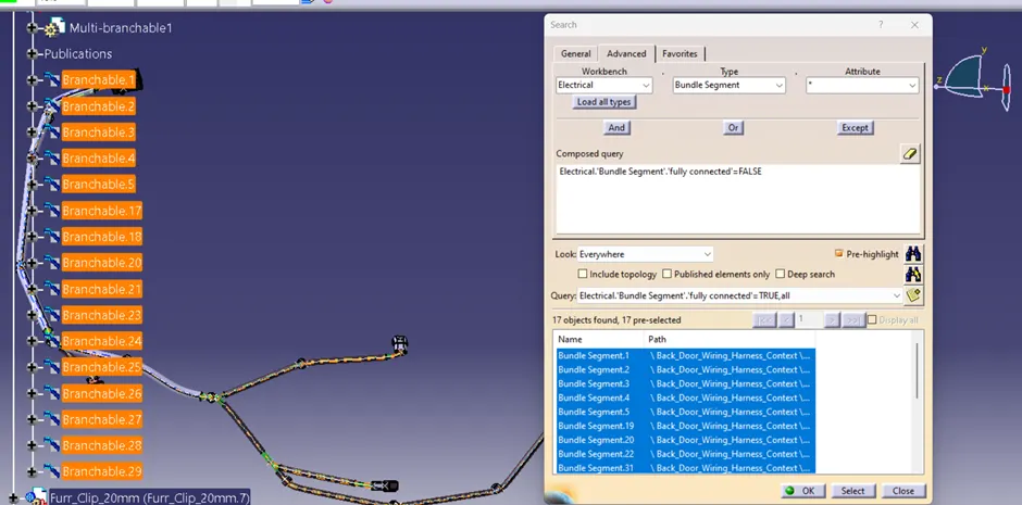
Figure n: Result when query "is fully connected" -True
PROCEDURES AND STEPS FOLLOWED FOR FLATTENING AND DRAWING
- Created new product and named “Flattening TailGate CableRouting”. Then jumped to electrical harness flattening work bench.
- Provided Harness Flattening Parameters.
- Then using extract command, the tail gate flattened routing is created.
- Using the commands like rotate, quick roll and roll etc. aligned the cables in a good manner.
- And saved the file
- Created new drawing document.
- Added front view of the routing flattened view.
- BOM table is created.
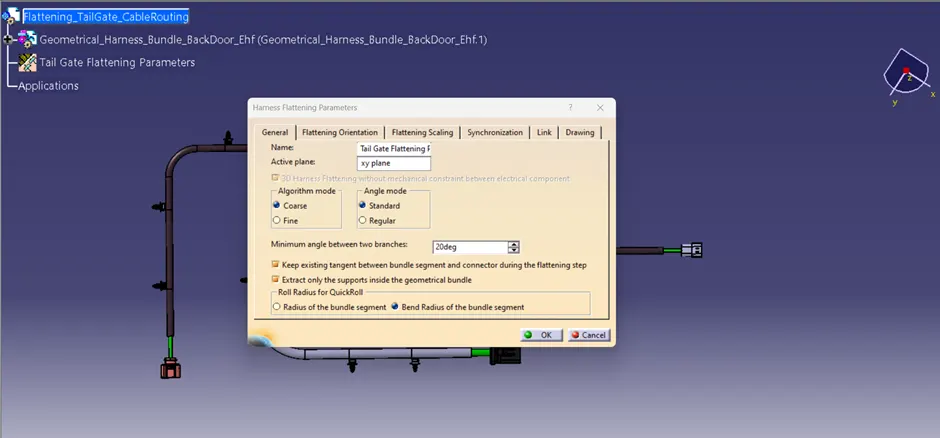
Figure o: Harness Flattening parameter tab
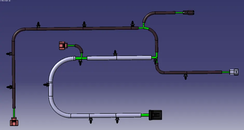
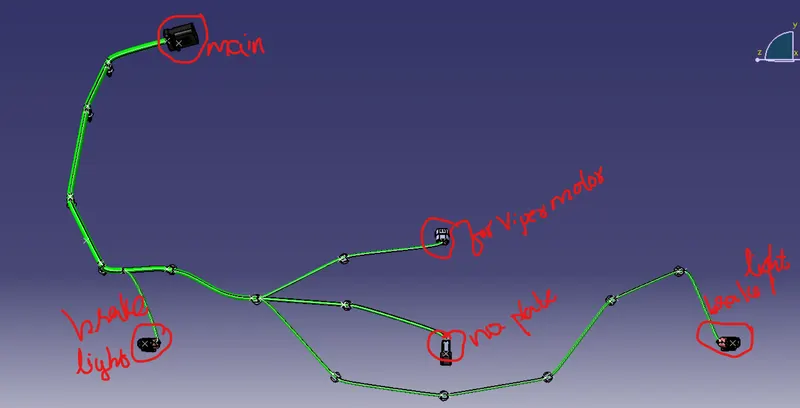
Figure p: Flattened view after aligning all the bundles
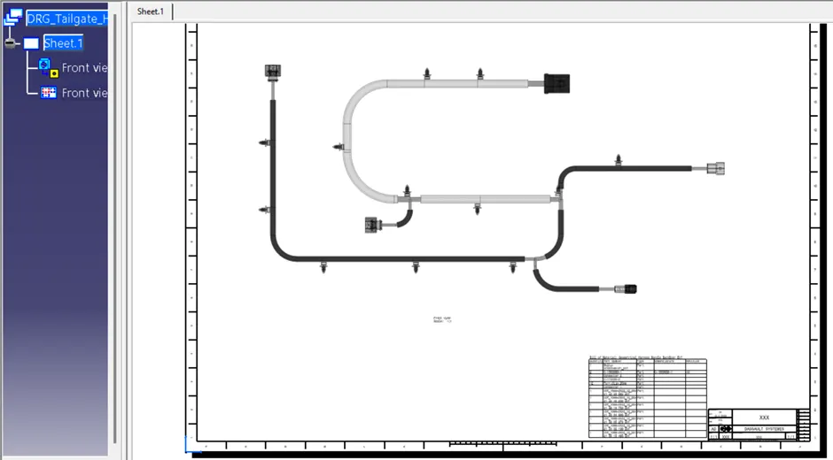
Figure q:Drawing sheet
SOME ROUGH SNAP DURING WORKING