Project 2
SOLUTION) :
Fuel cell electric vehicle model set-up:
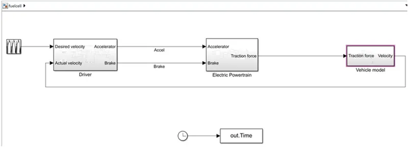
This model set-up consists of,
- Driver model
- Electric powertrain model
- Vehicle model
Driver block:
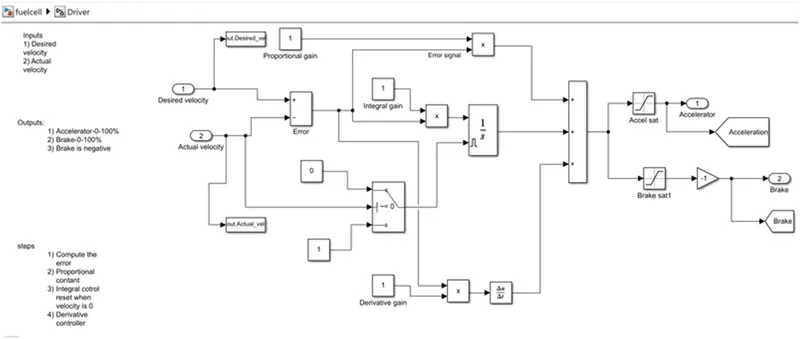
The PID controller is used to obtain the driver model. Two inputs is given as desired velocity and actual velocity. Two output is taken as accelerator and brake.
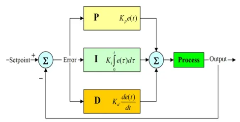
The formula to obtain a PID controller is given below.

Vehicle model block:
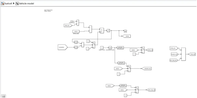
These are the formula to obtain vehicle model.
Rolling resistance:
Fr = M*g*u*cos(u)
M - mass
g - gravity
u - angle of slope
Aerodynamic drag:
Fa = (1/2)*delta*Af*Cd*(V*V)
Delta - density of surrounding air
Af - vehicle frontal area
Cd - drag coefficient
V - velocity of vehicle
Grade resistance:
Fg = M*g*sin(u)
M - mass
g - gravity
u - angle of slope
Electric power train model:
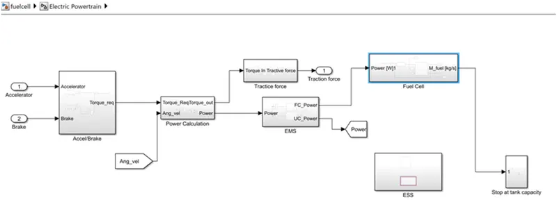
The power train model consists of,
- Battery model
- Fuel cell model
- Ultracapacitor model
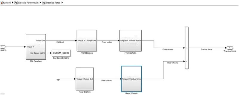
The tractive force is given as below.
- motor map has to translate to vehicle velocity
- this is done by tractive force
- tractive force is fed to vehicle velocity
The gear box output is depend on torque input from energy management and efficiency of gear box.
Wheel angular velocity=veh. velocity/veh. radius of tire
EM speed=gear box ratio*wheel speed
Brake torque= brake signal*veh.mass*ground friction*gravity*tire radius
Torque= radius of wheel*force
Velocity= radius*angular velocity
Fuel cell model:
- stack current/area of FC determines current density
- cell polarisation curve plot stack voltage from current density and cathode presure
- cathode pressure by current demand from FC
- EMS decide power to demant from fuel cell
- FC has feedback loop to minimum difference between demand and actual
- power demand fed to power Vs current map
- compressor run on current Vs rpm map to neccessary oxygen
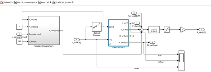
This the subsystem for fuel cell,
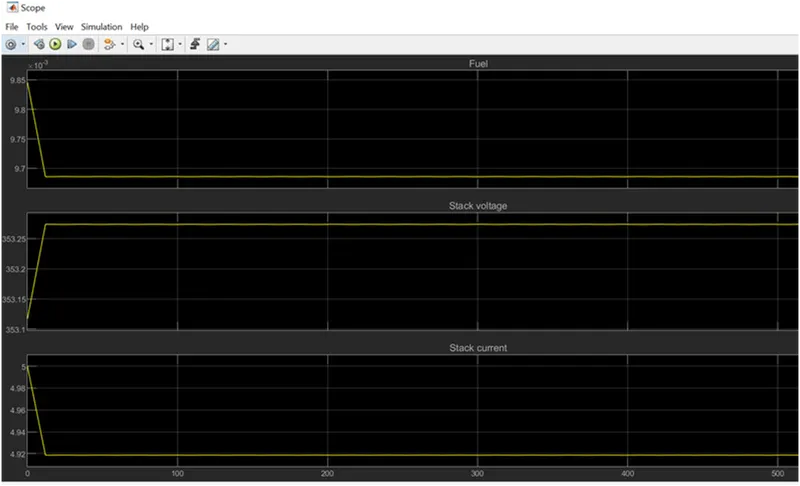
Result is shown from the fuel cell,