Project 2
Introduction : By using revit, we can get the realistic view of how the model which we created will be once we completed. By using dynamo, we can create the model by using visual script with nodes.
1) Twisting tower
Aim : To create one model multi storeyed twisting tower with maximum architectural features.
Procedure:
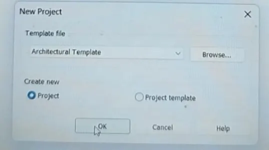
Launch revit software. Click on new and select architecture template and click on ok.
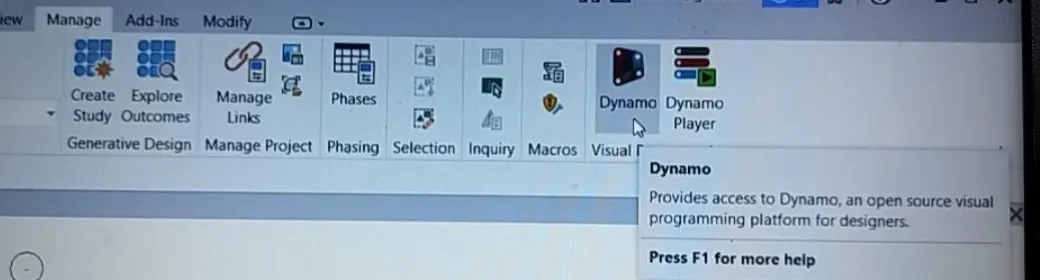
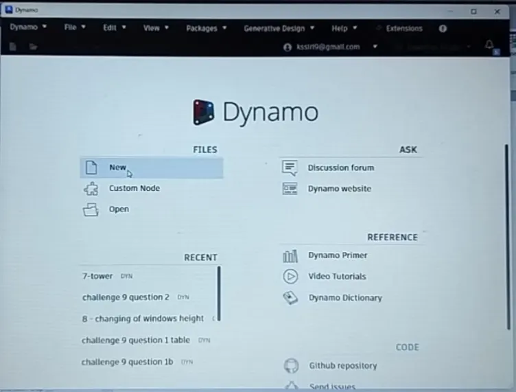
Click on dynamo present in the manage tab. A dialogue box will appear and click on new .
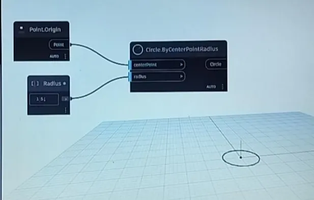
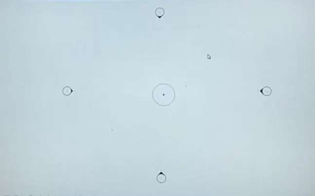
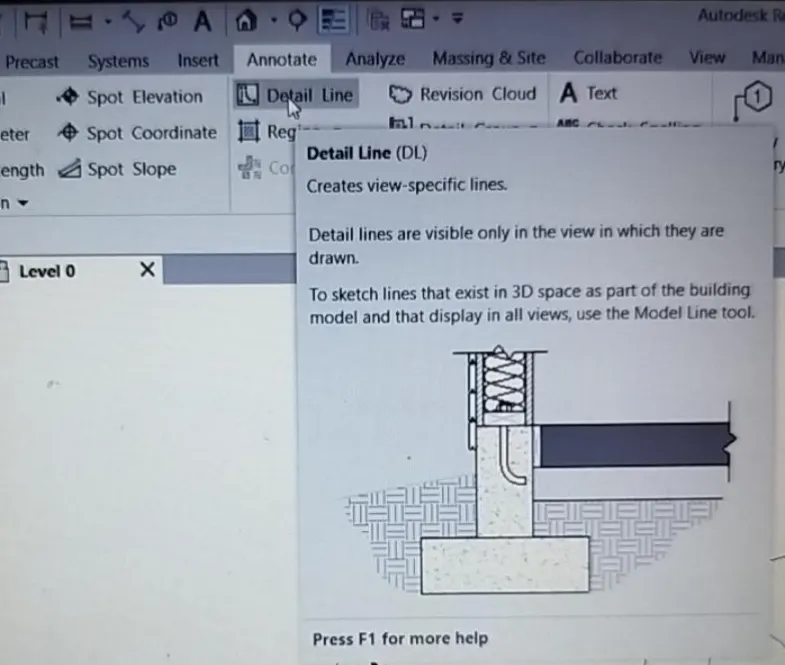
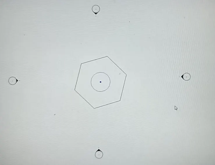
Select circle by centre point radius with input as point origin and radius as 5. We can see circle at centre. Now go to revit and we can see circle formed in the level 0. By using detail line present in annotate draw the polygon around the circle.
Search for select model elements in revit. Click on select in dynamo and select polygon which we have drawn in revit. Elements location will be automatically displayed in the model elements in dynamo. Search for element geometry in dynamo and give input as output of select model elements. Now search for flatten list and attch the previous output to the input. Search for polycurve by joined curves and attach output of list to the input of curves. Now attach the output of polycurve to the geometry input of geometry transform.
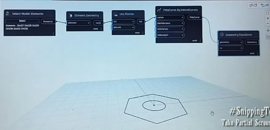
Now for the input of CS in geometry transform . We should search for coordinate system by origin in which input of only z should be given. Input of z is height of the tower and space . The output of coordinate system by origin will be the input of the CS in geometry transform. After joining we will see the geometry figure in dynamo. By changing the space we can see change in the dynamo outline.
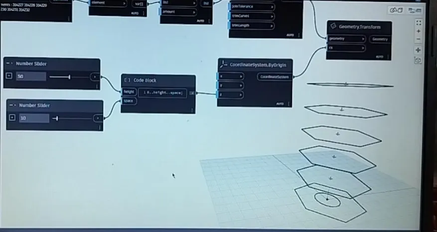
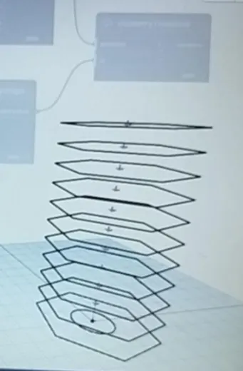
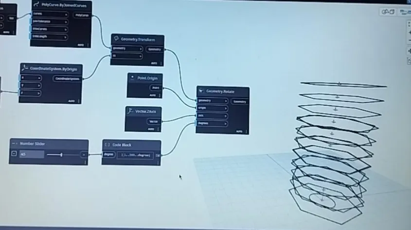
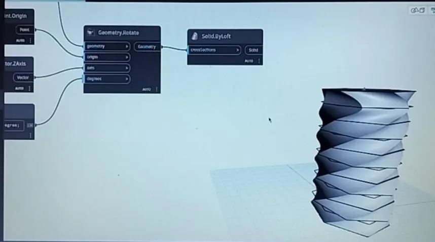
Search for geometry rotate and select it. Now Give the input of geometry rotate with output of geometry transform, point origin , vector z axis, degree. Now we can see at what angle we can rotate the tower. Add solid by loft. Input for solid by loft will be output of geometry rotate.
Result:
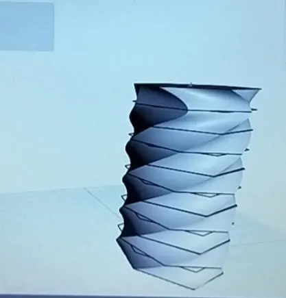
We can see solid form of the twisting tower as below.
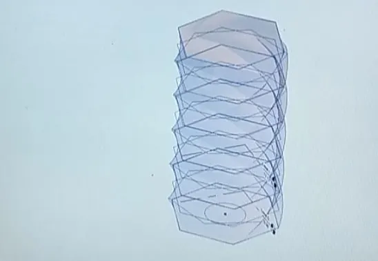
We can also see the twisting tower in revit 3D view as below.
2)To add facade design
Aim : To add facade design using massing for twisting tower.
Procedure: Open twisting tower which we have created previously in revit.
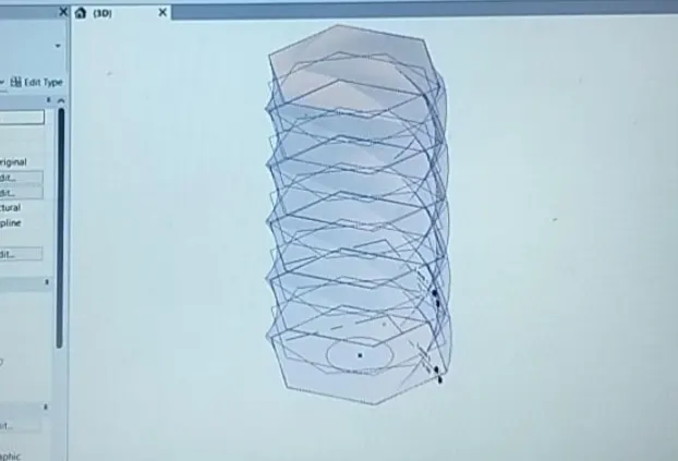
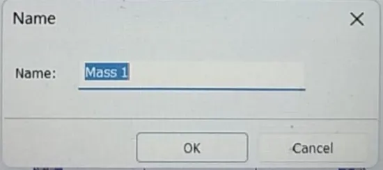
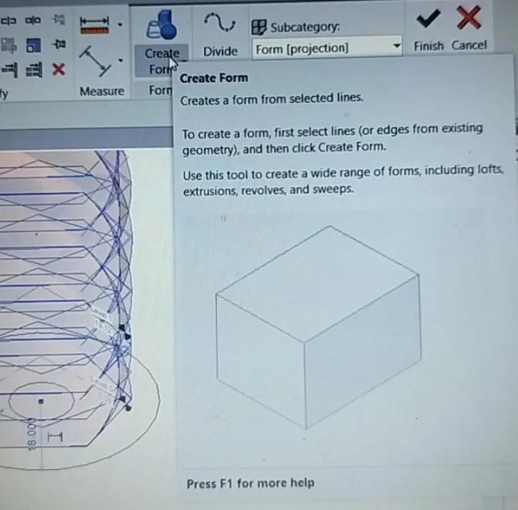
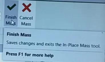
Select in place mass option present in massing and site. A dialogue box will appear which contains name. Type the name and click on ok. Now go to revit 3D view top elevation plan and draw circle around tower . Create solid form and click on finish mass.
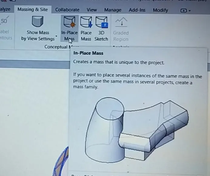
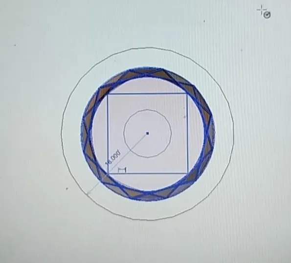
Solid form created around tower will be as below.
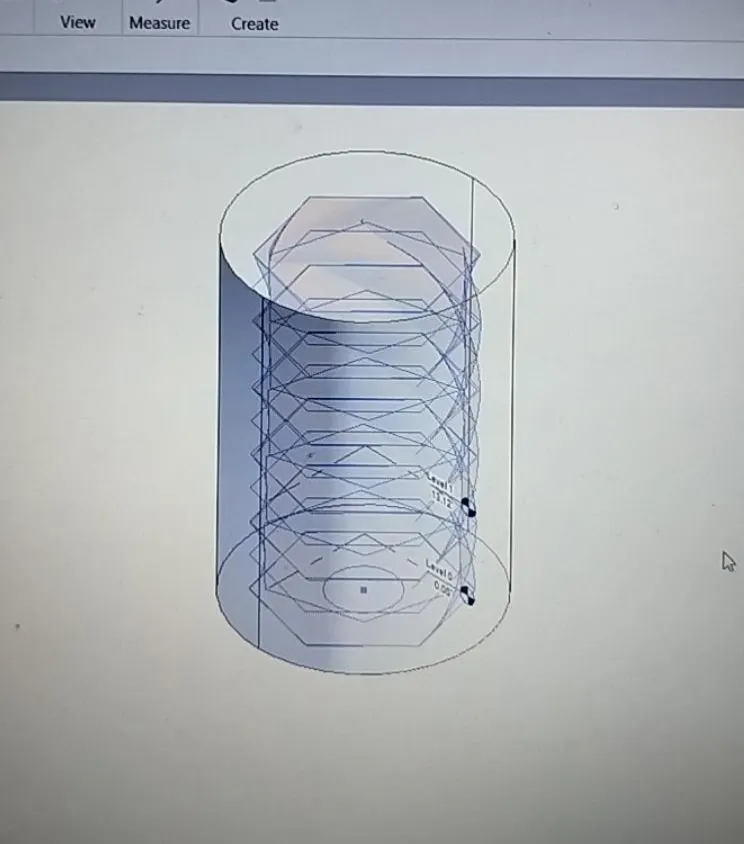
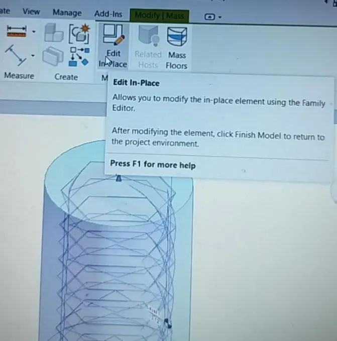
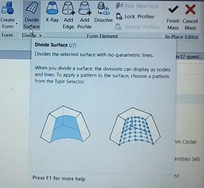
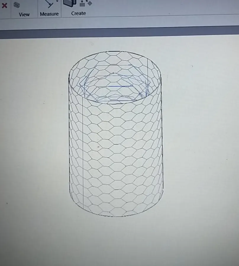
Click on solid form created. Select edit-in-place option. Now select the solid surface and click on divide surface. Now select the type of pattern you want from properties. Click on finish mass. Facade deign for tower is added.
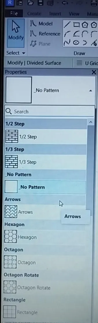
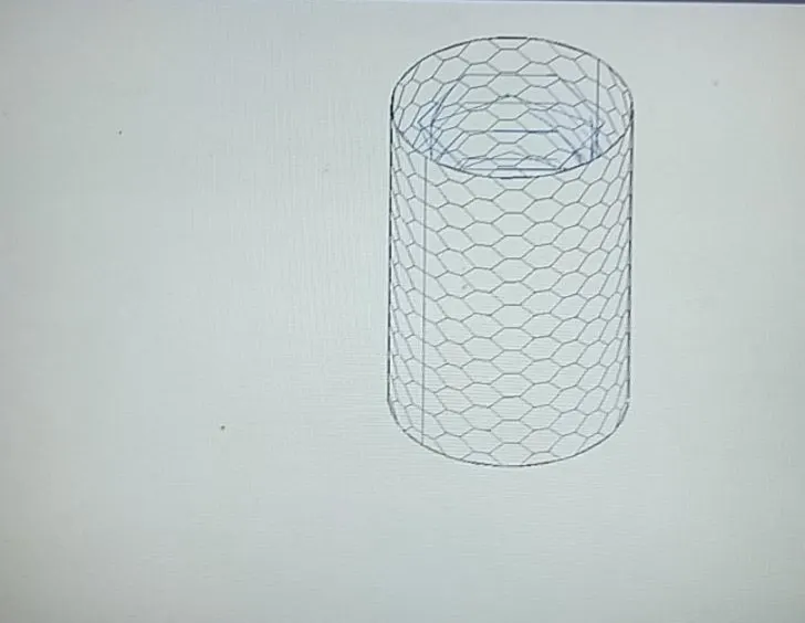
Result: Facade deign for the twisting tower is added.
3)To print 3D Views from different locations.
Aim : To print 3D Views from different locations and to create walk through videos as well as exterior rendered images.
Procedure : Open revit file of project 1.Go to 3Dview and click on the camera. Project the camera as you want in different views and in different directions. All different views will be saved in 3D Views. We can create different sheets by using them and we can also print them.
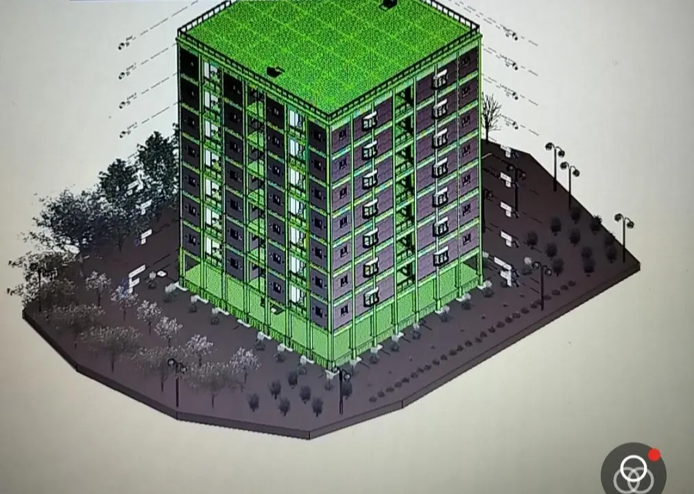
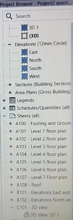
Click on sheets present in project browser. In sheets we have already created 3D view sheet. Click on it and sheet which we created will be shown.
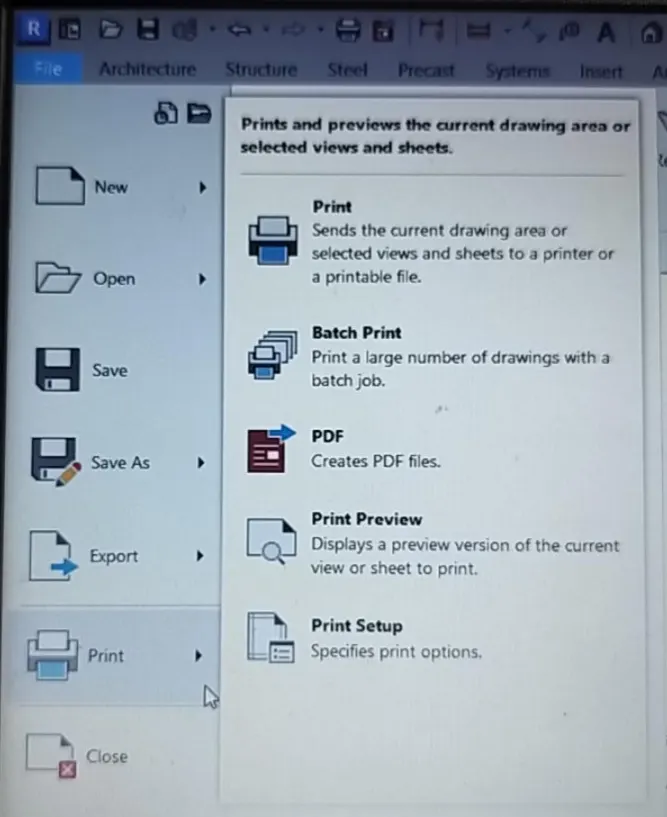
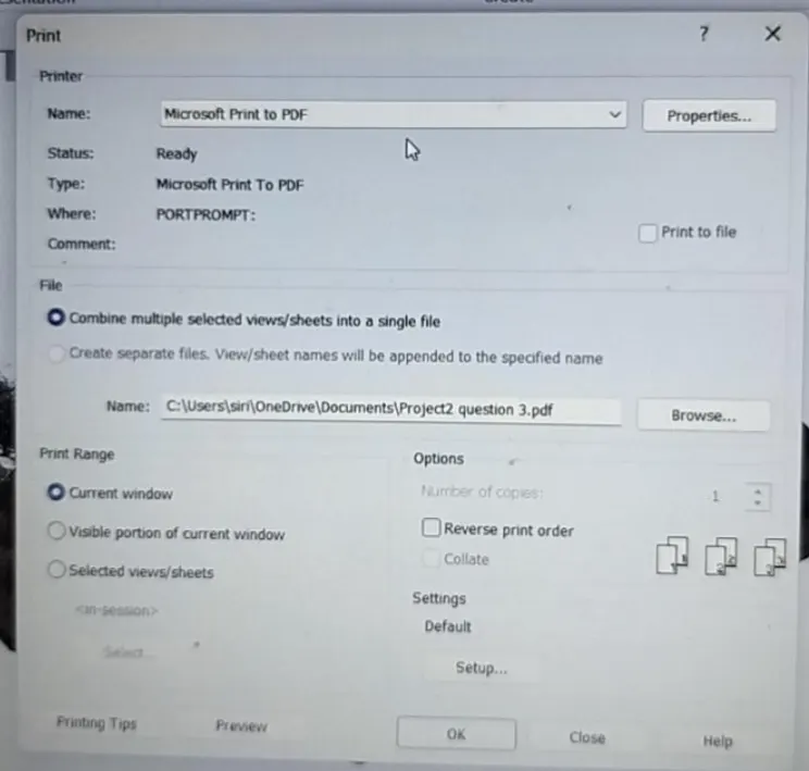
Press print present in file tab. A dialogue box will appear. By pressing on ok we can print the required sheet. We can also save the sheet as pdf by changing printer option to pdf.
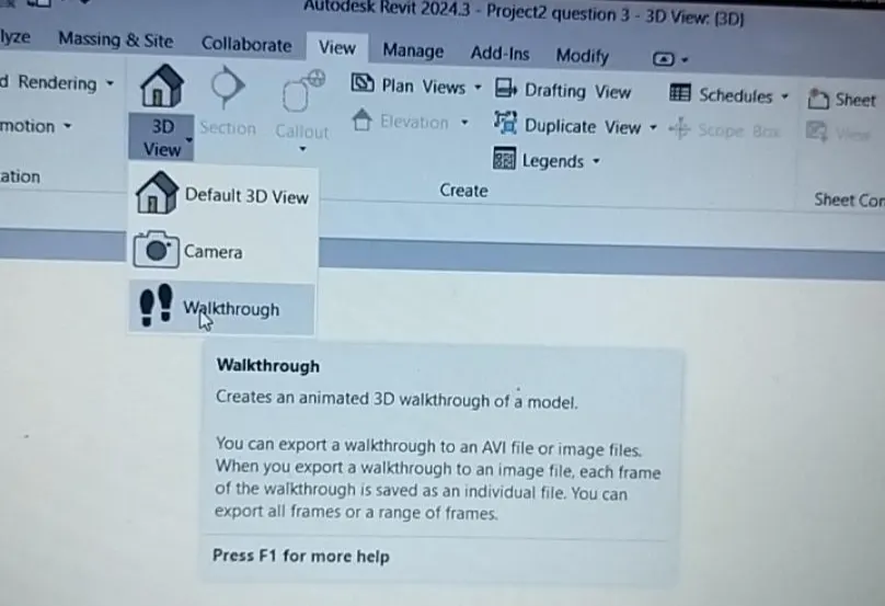
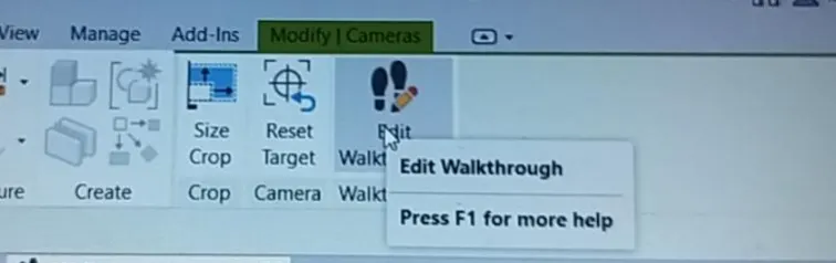
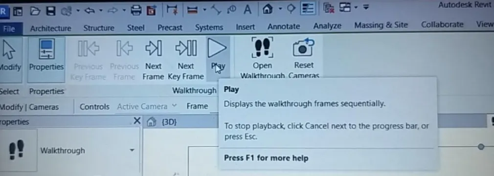
For walk through, click on walk through present in 3DView in the view tab. Select any floor plan and click on walk through and draw the path through which you want walk through. By clicking on edit walk through, and clicking on play we can see the video of walk through. Similarly we can play walkthrough of the exterior model. We can see the walk through we created in project browser.

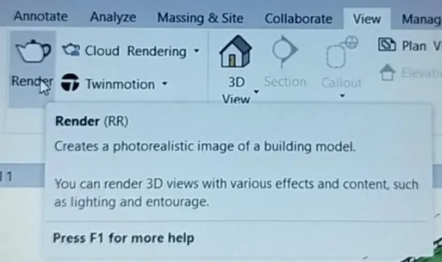
For rendering, open any 3DView. Click on render present in the view tab. A dialogue box will appear, We can change the settings or background or lighting and then click on render. Render image of the 3Dview will be formed.
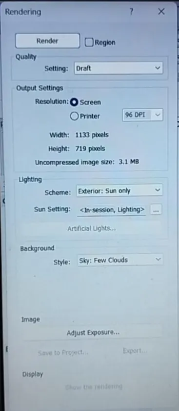
Similarly we can create render images for different 3Dviews. We can also print them by creating sheets and by following above procedure. Some of the render images are as below.
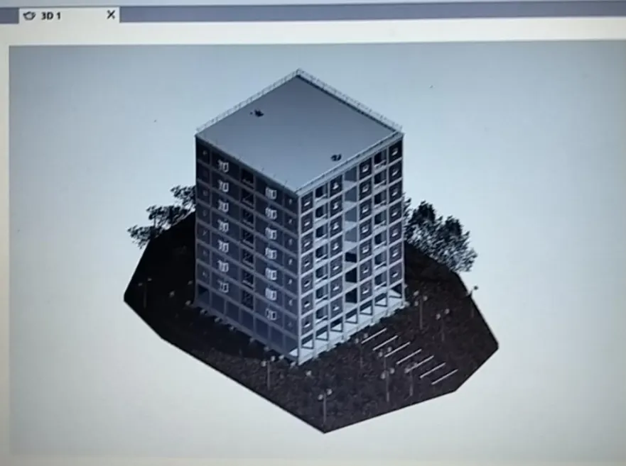
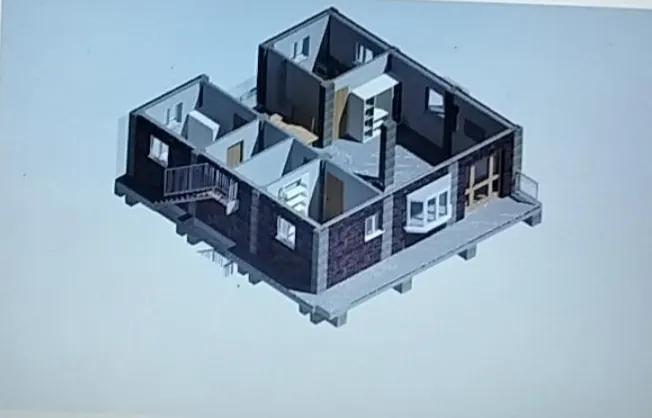
Result : For the model, we can print, go to walkthrough and render.
4)Aim : To prepare a report regarding the pros and cons of applying the BIM processes in the project.
Pros:
- It helps in better communication, collaboration between the team members.
- It helps in execution of the project at correct time.
- It helps us to reduce errors/ clashes of elements in the project.
- It saves time .
- It helps in reducing cost of the project.
Cons:
- Cost of the software
- Lack of skilled professionals
- Lack of usage/knowledge of the BIM by the customer or contractor.