Creating Architectural and Structural model with 3D rendering using REVIT
1) The type of structure I want to build is multi unit residential building.
2)Aim : To identify the modelling requirements based on assumptions for regional and location details for your project based on NBC.
Introduction : The NBC is a national building code , a national instrument providing guidelines for regulating the building construction activities across the country. The modelling requirements for a multi unit residential building are assumed based on the regional and location details of the NBC.
Procedure :
- This model is on a plain terrain. It comes under NBC Part 4 fire safety , group A : residential buildings and subdivision A-4.
- The basement height is in between 2.5 m to 4.5 m.
- Height of the room is 10 feet.
- Thickness of a wall is 8 inches.
- The minimum staircase width is 1.25m.
3) Aim : Using the structural model, include different components related to structure.
Introduction : The structure model components include framework of a building like foundation, columns , beams, floors, roof, shaft openings in floor for elevators and stairs.
Procedure :
Open structure template in new and save the file. Now by using collaborate tab make this structure template as a central model and synchronise it. Now draw grids one horizontal and other vertical. Select the manage tab to specify coordinates as 0',0' and save it by synchronising the model. Now close the structural model.
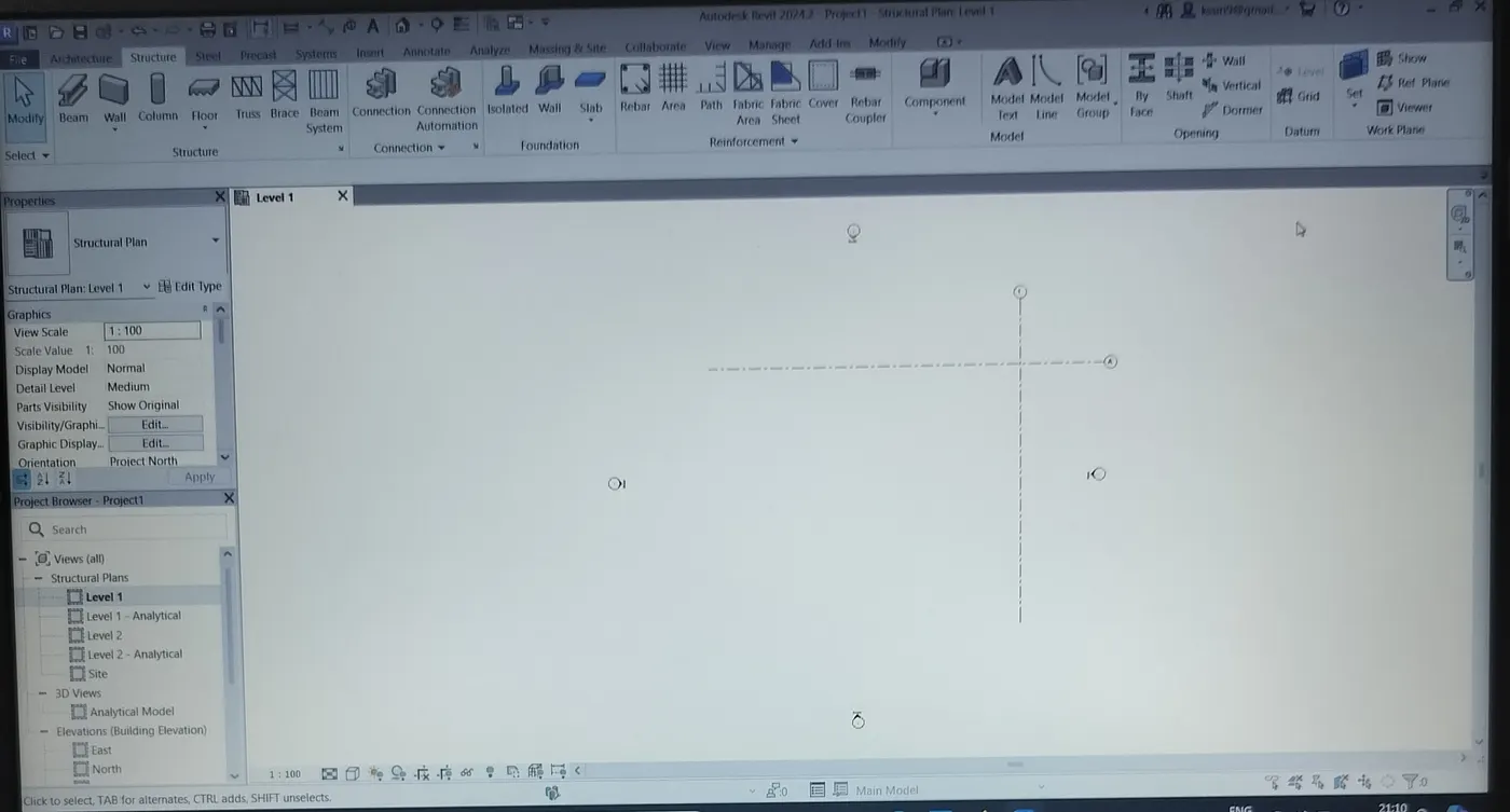
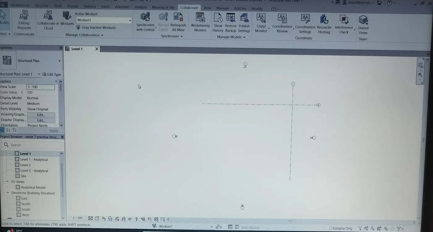
Open architecture template in new and save the file. Now by using collaborate tab make this architecture template as a central model and synchronise it. Now draw grids one horizontal and other vertical. Select the manage tab to specify coordinates as 0',0' and save it by synchronising the model.
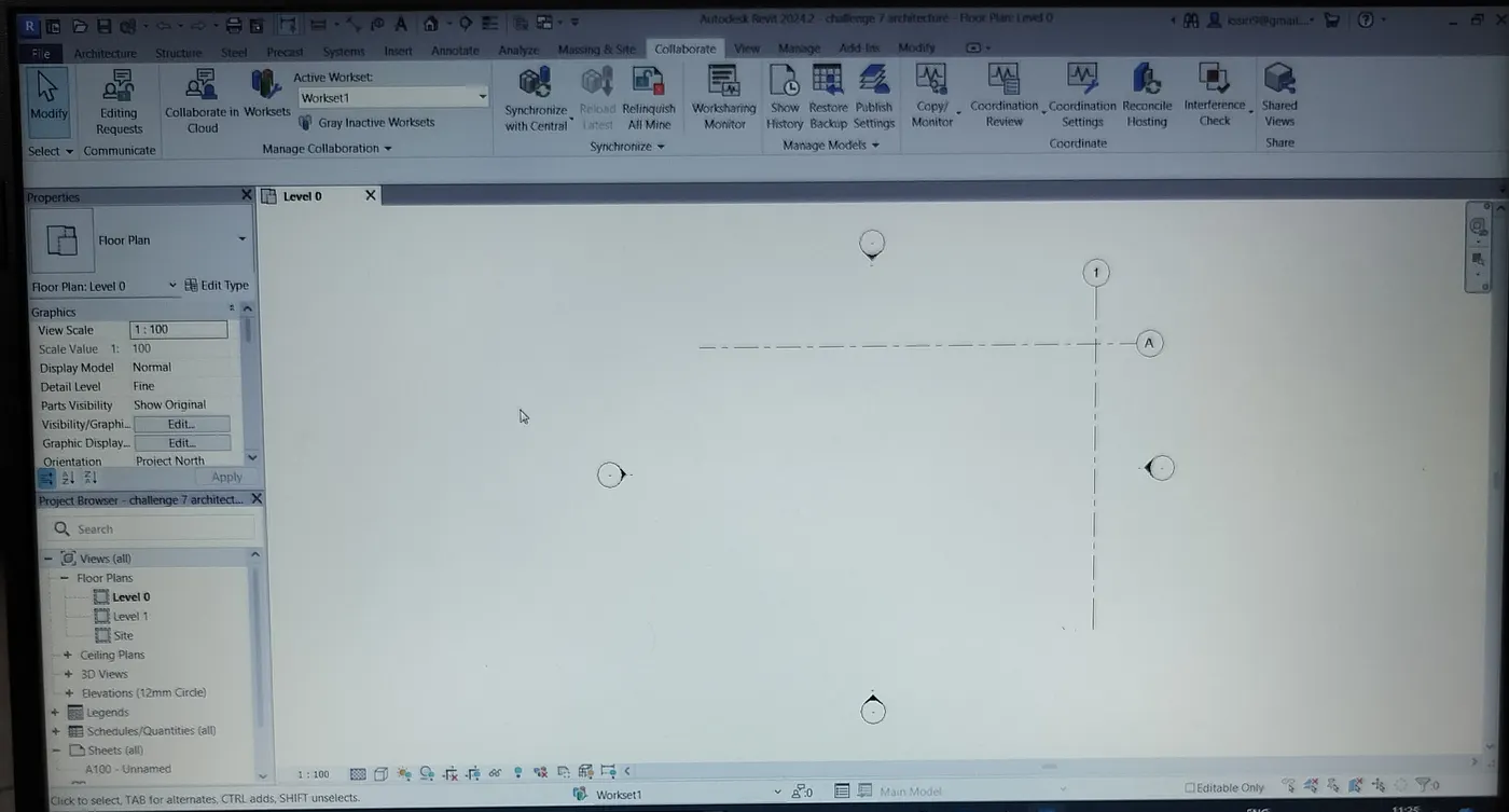
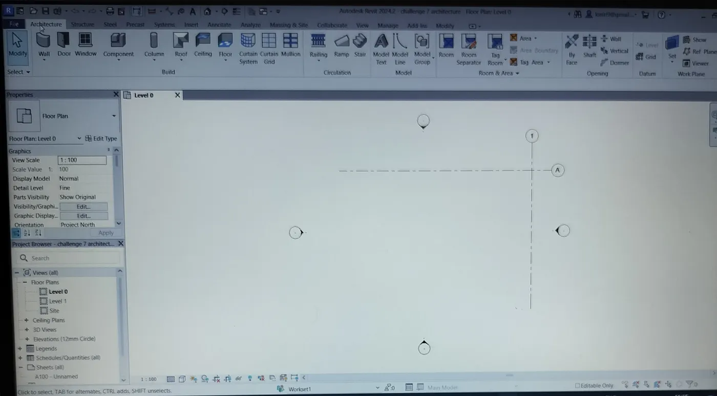
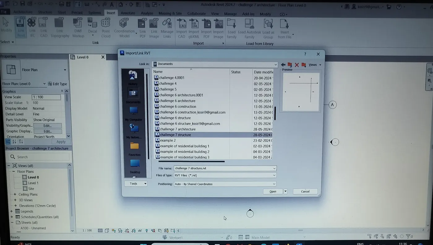
Open manage tab and select manage link and add structure model into architecture model or open insert tab and select revit link and link structural model by using shared coordinates. Both grids will appear. Now select acquire coordinates and select the link. Now specify the coordinates. Both the grids of structural and architectural model will overlap. Save the file by synchronising the central model. Now close the architectural model.
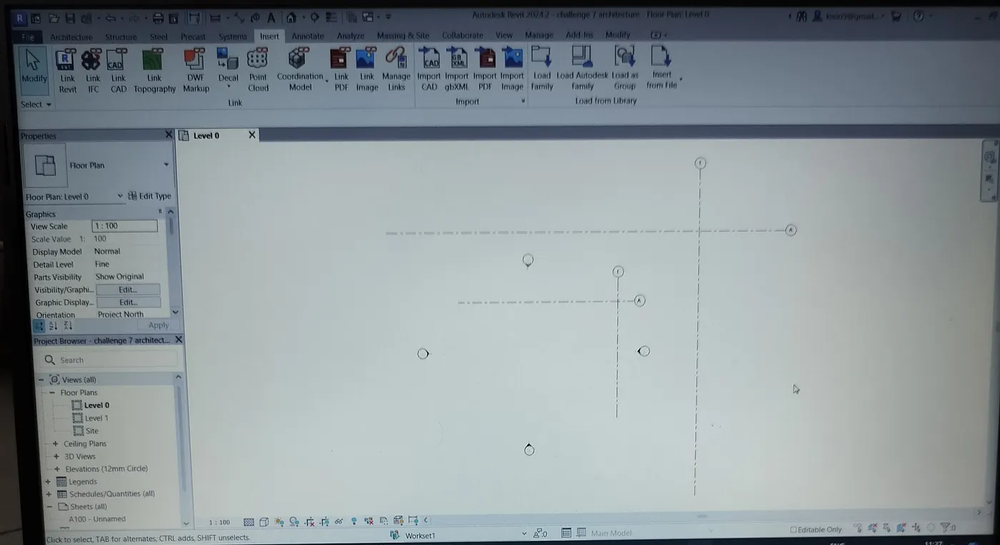
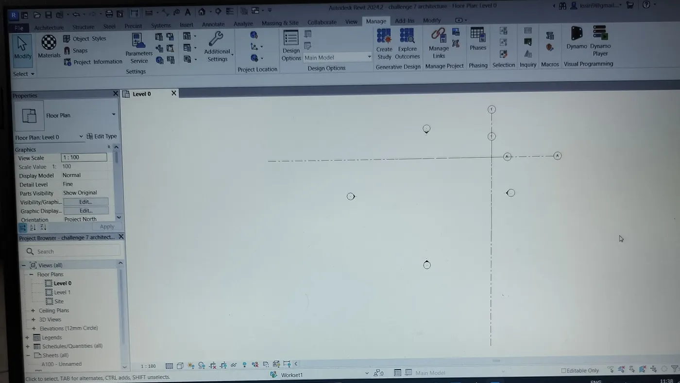
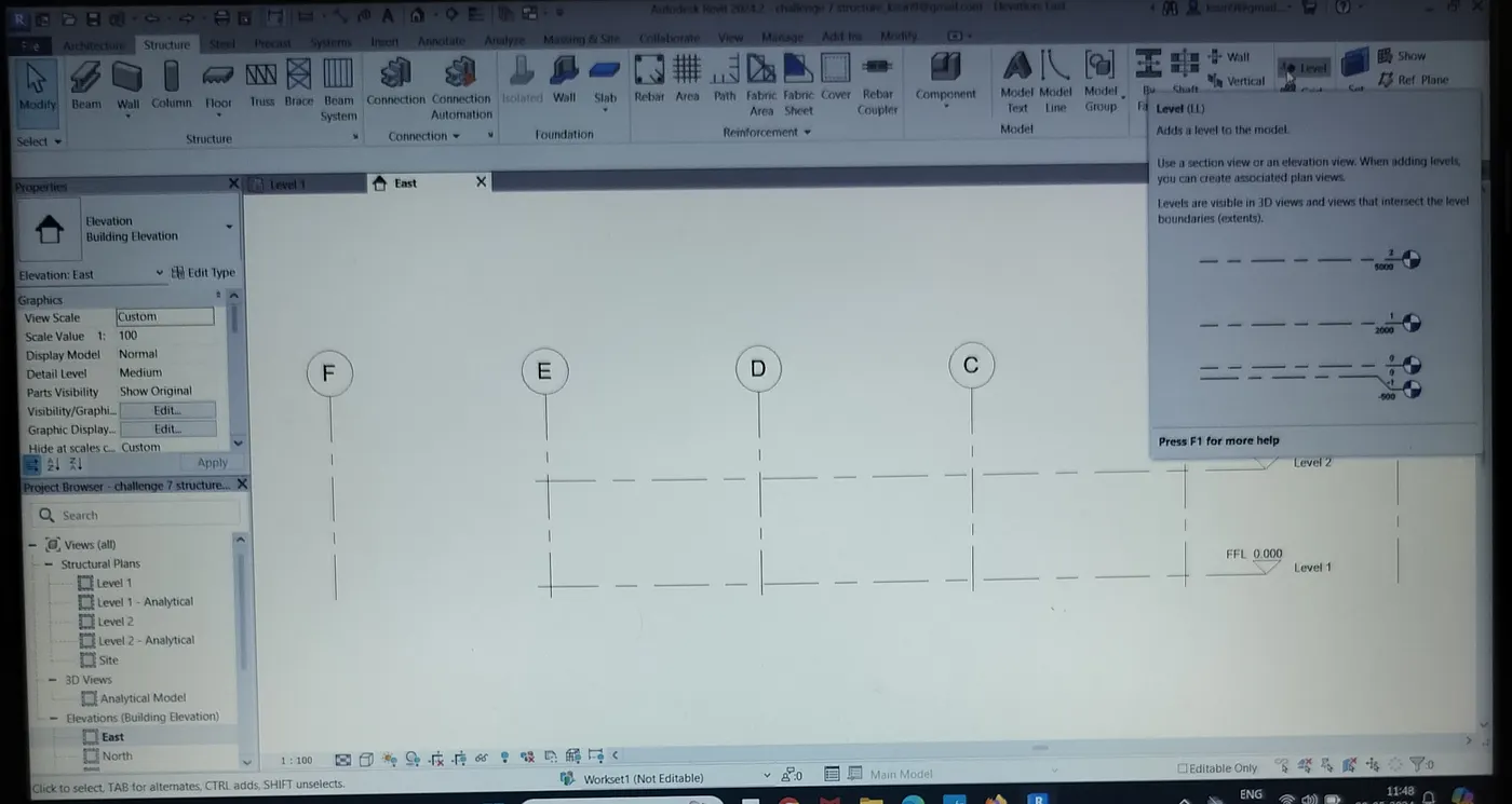
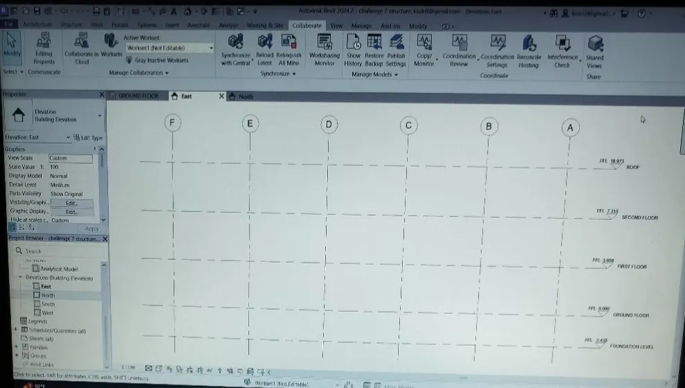
Open the structural central model which we saved above. Select the grids in structure tab and draw grids with an offset of 20 feet both horizontal and vertical. Open one of the elevation views and add different levels by renaming them and at a specific distance.

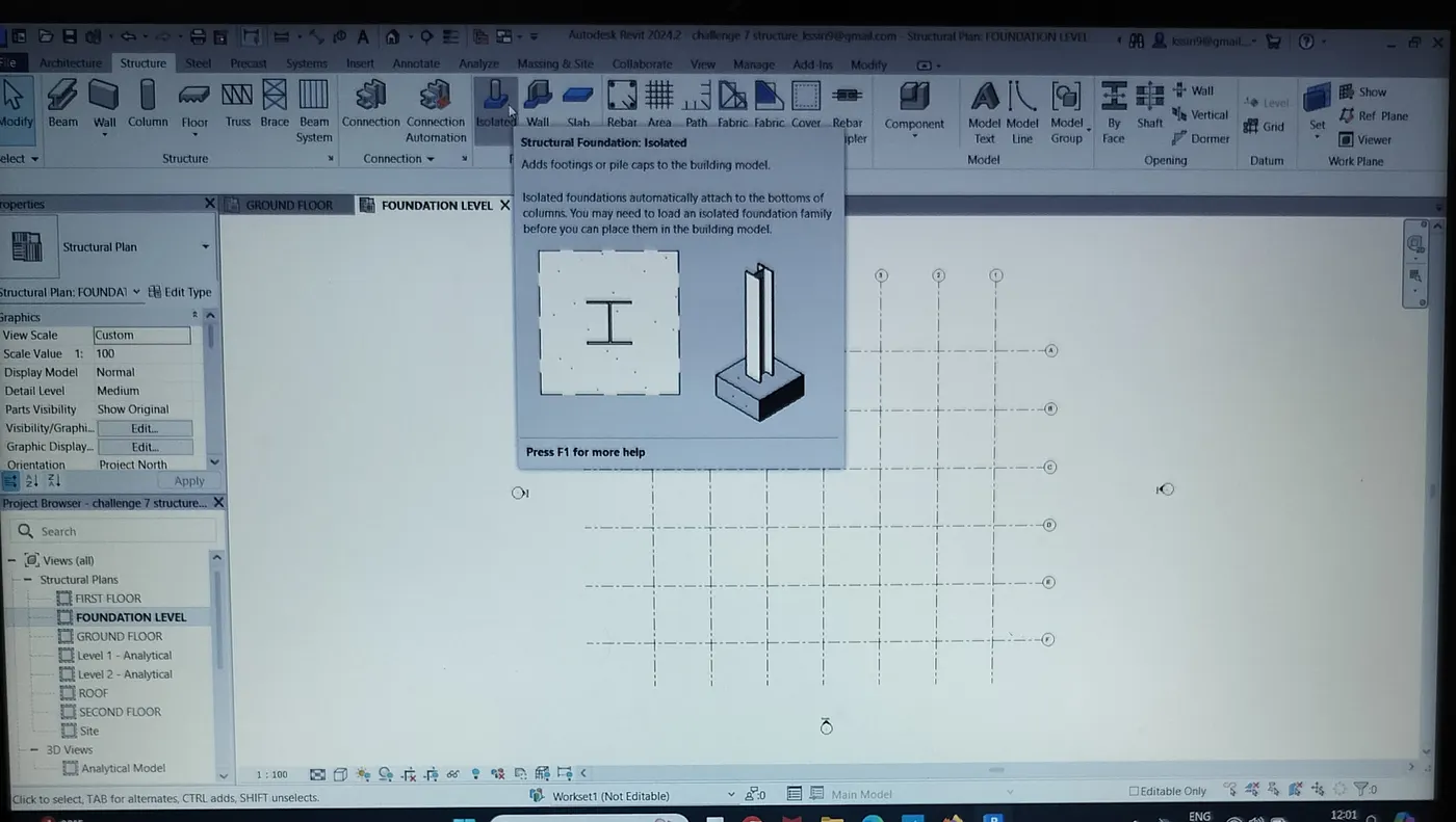
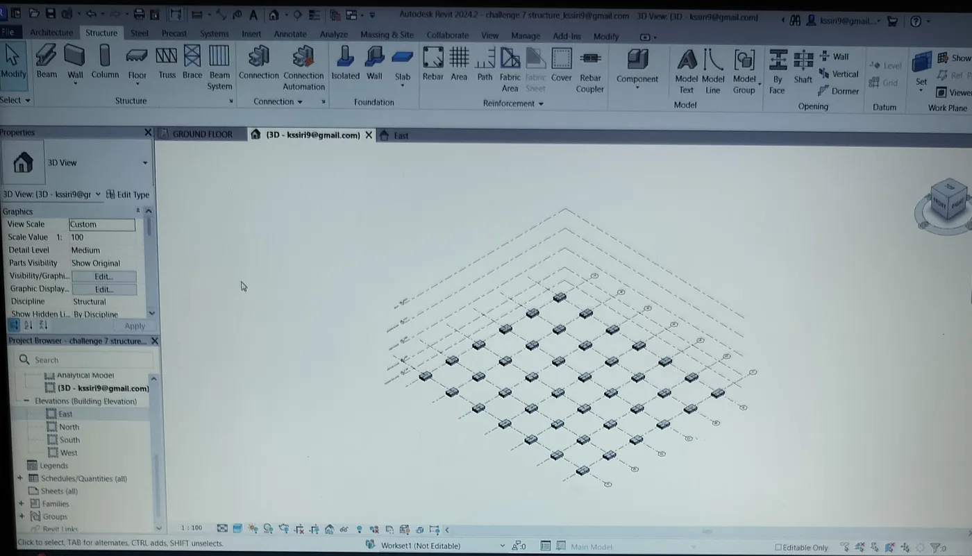
Open foundation level. Select isolated foundation in structure tab. Now select at grids and select all grids. We can see foundation at intersection of grids and click on finish.
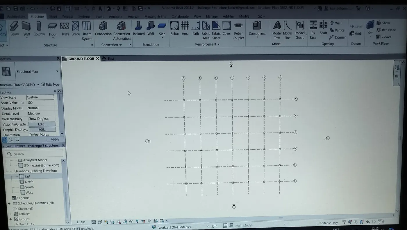
Open ground level. Select columns in structure tab and select the desired column in properties. Now select at grids and select all grids. We can observe columns at intersection of grids and click on finish.
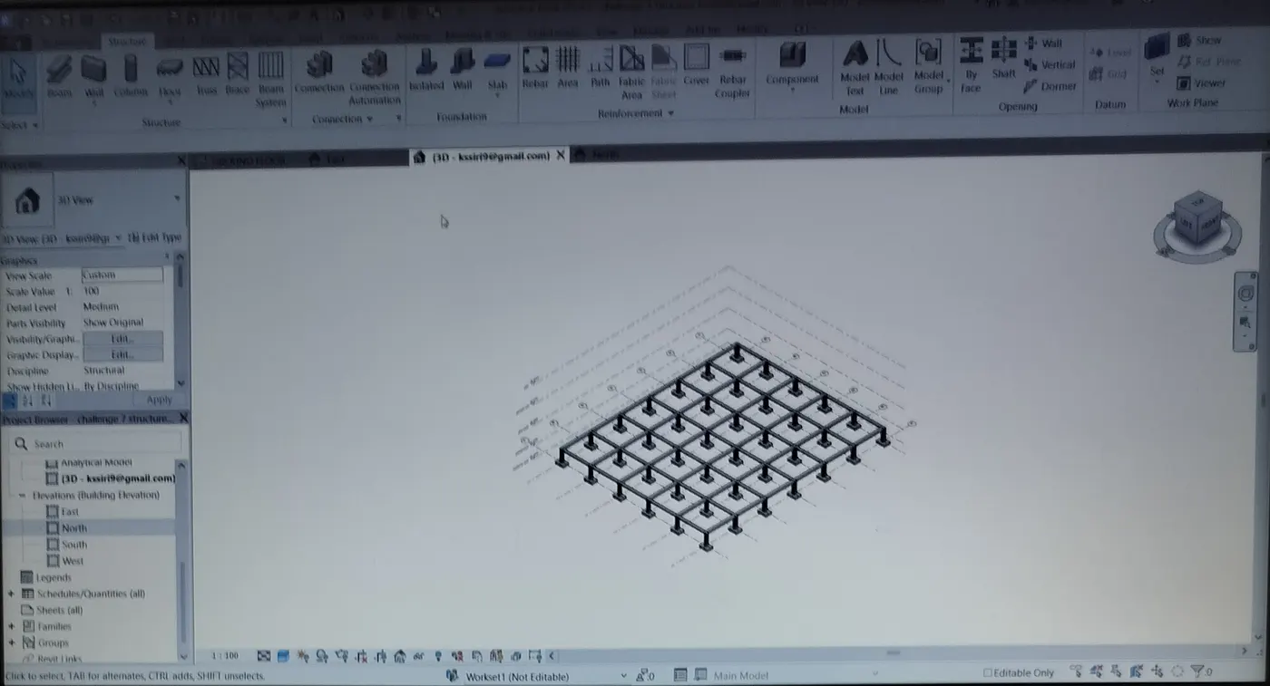
Select beams in structure tab and select the desired beam in properties. Now select on grids and beams are formed on grids between columns.
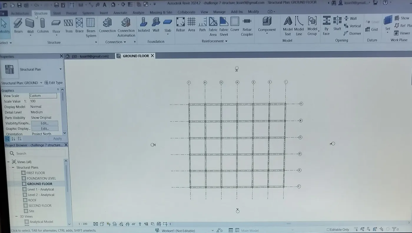
Select columns, beams in the ground floor. Copy them to clipboard and paste them to alligned to selected levels. We can see all are copied to different levels.
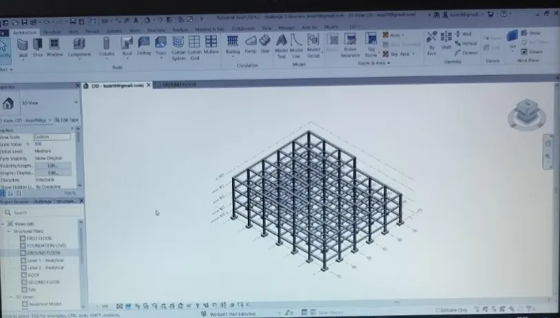
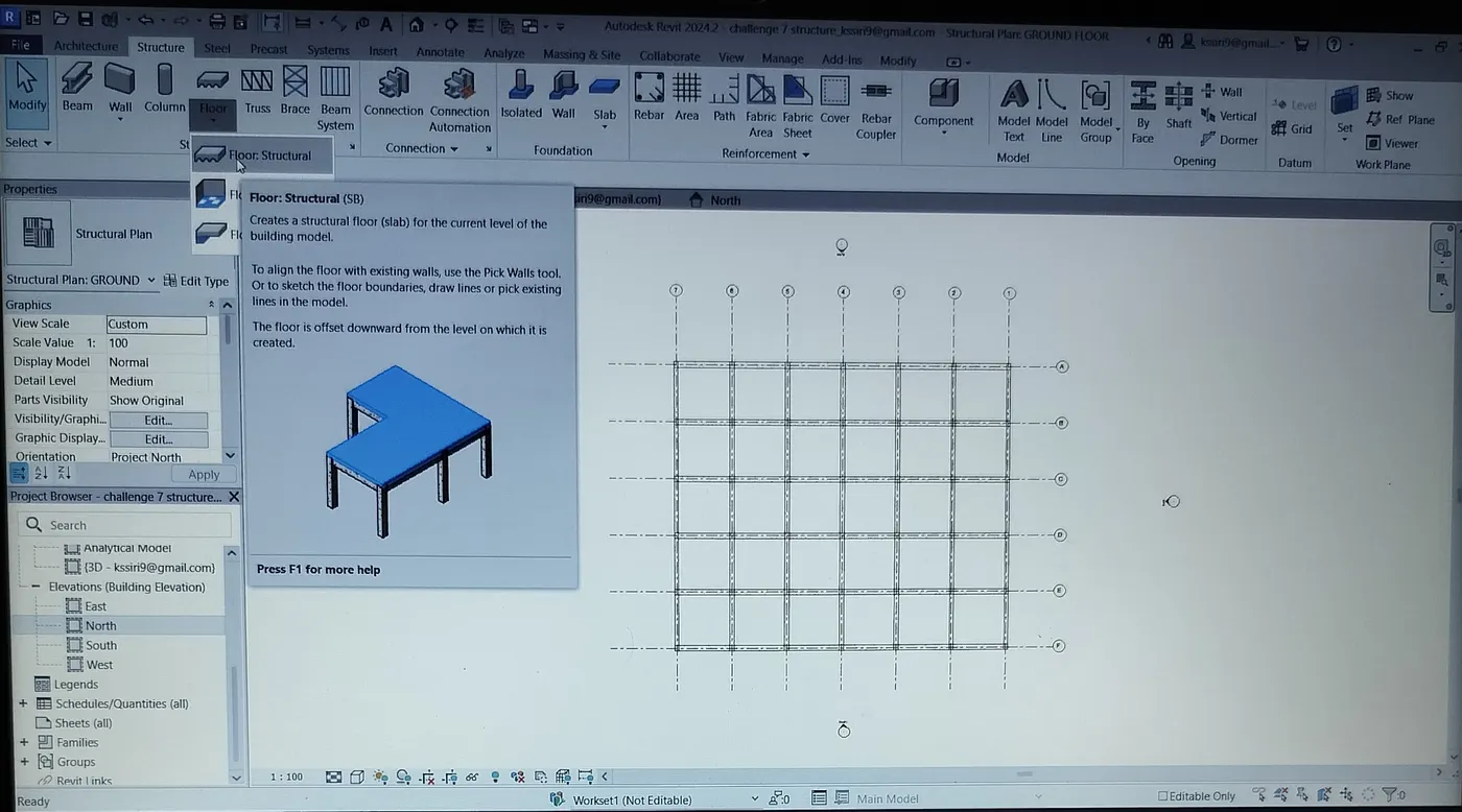
Open ground floor plan. Select floor in structure tab. Now pick a line and draw boundaries and click finish. We can see floor in model. Now copy and paste the floor to different levels.
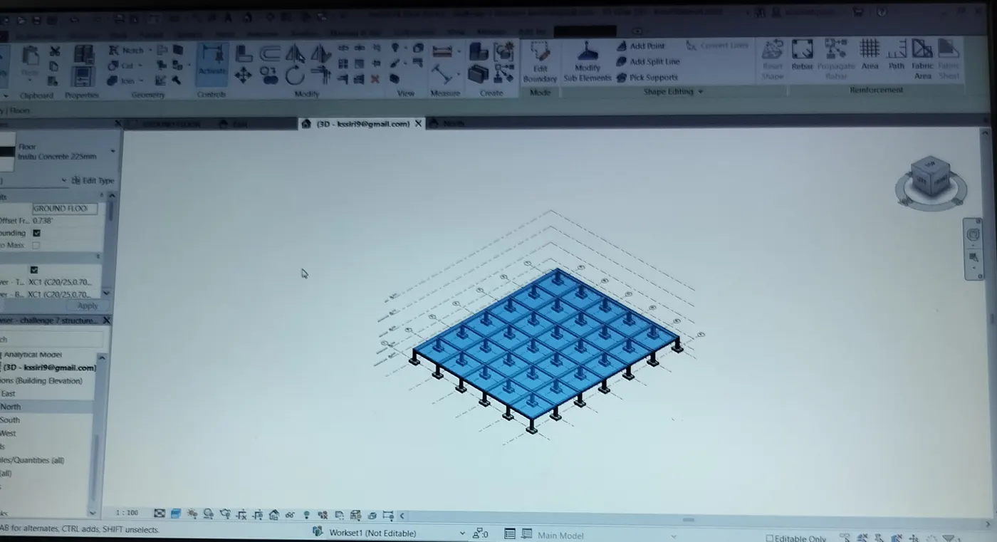
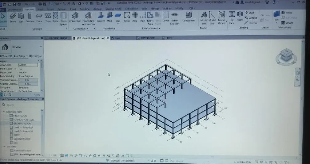
For staircase and elevator , openings in the floor should be given by shaft openings present in the structure tab.
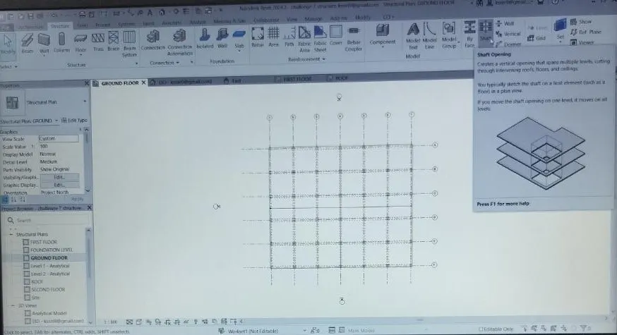
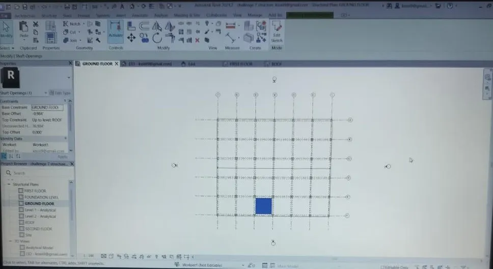
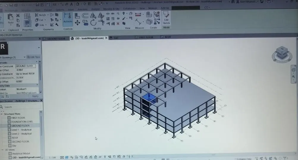
Result : Completed the structure model framework with footings, columns, beams, floor and shaft openings for stairs and elevator.
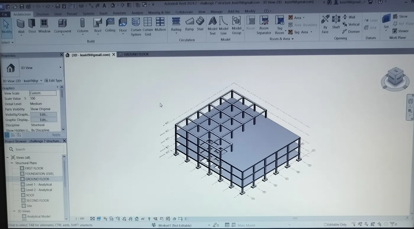
4) Aim : Using architecture model , include different components related to architecture.
Introduction : Architecture model components include walls, doors, windows , stairs , elevators, interior components like sofa, bed, plumbing fixtures , etc.
Procedure :
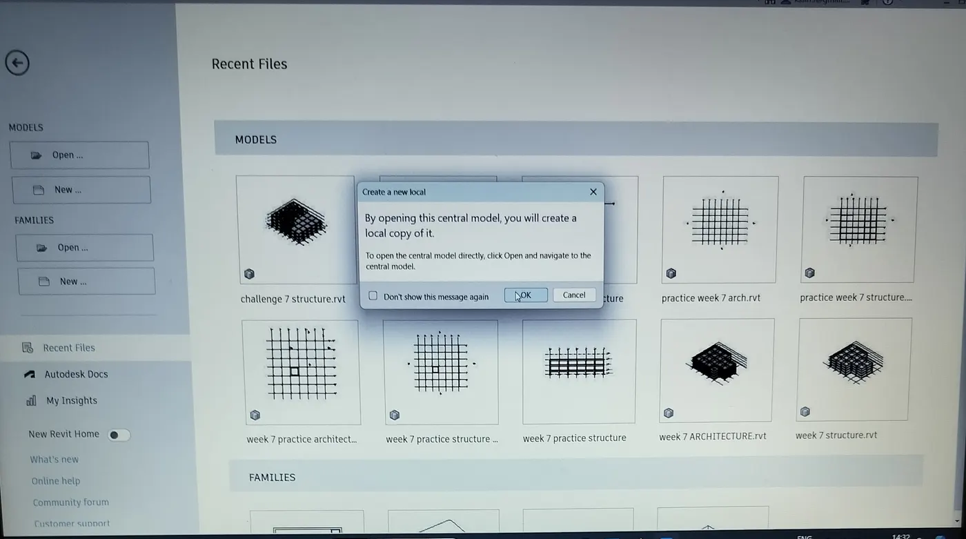
Open the architecture model which we saved as a central model. We will see all the changes from structural model will be reflected in architecture model as we have linked structure model into architecture model.
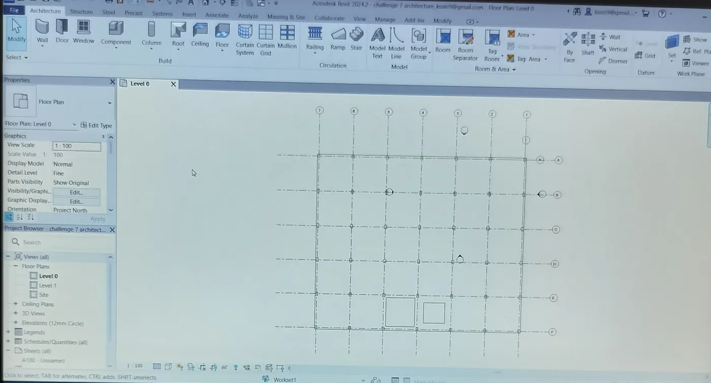
Select copy/monitor from collaborate tab and select link. Now click on copy, select all the grids and then click on finish. Now go to visibility/graphics setting and select custom in revit link. Click on annotation categories in revit link display settings and select custom. Deselect grids and click on apply and ok. We can see that grids are copied into architecture model and grids from structure model are not present.
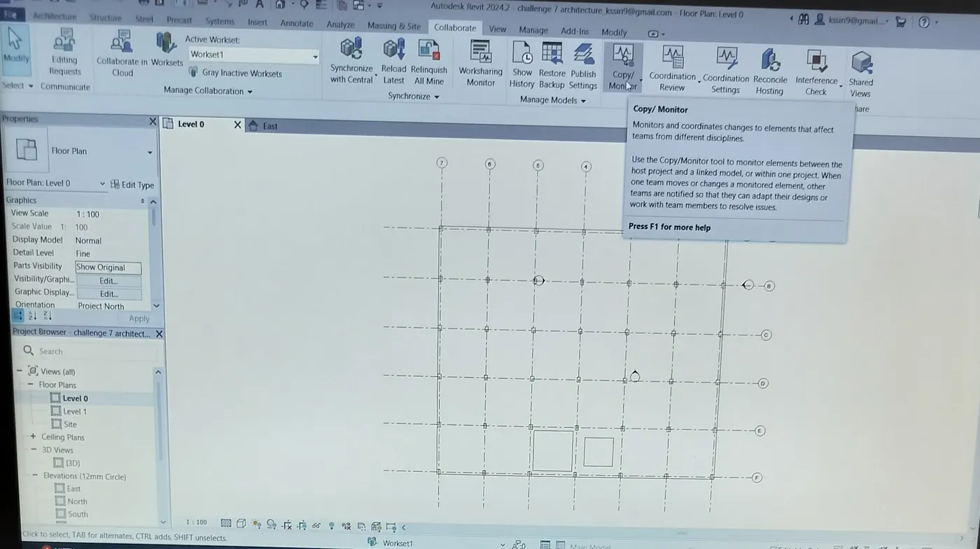
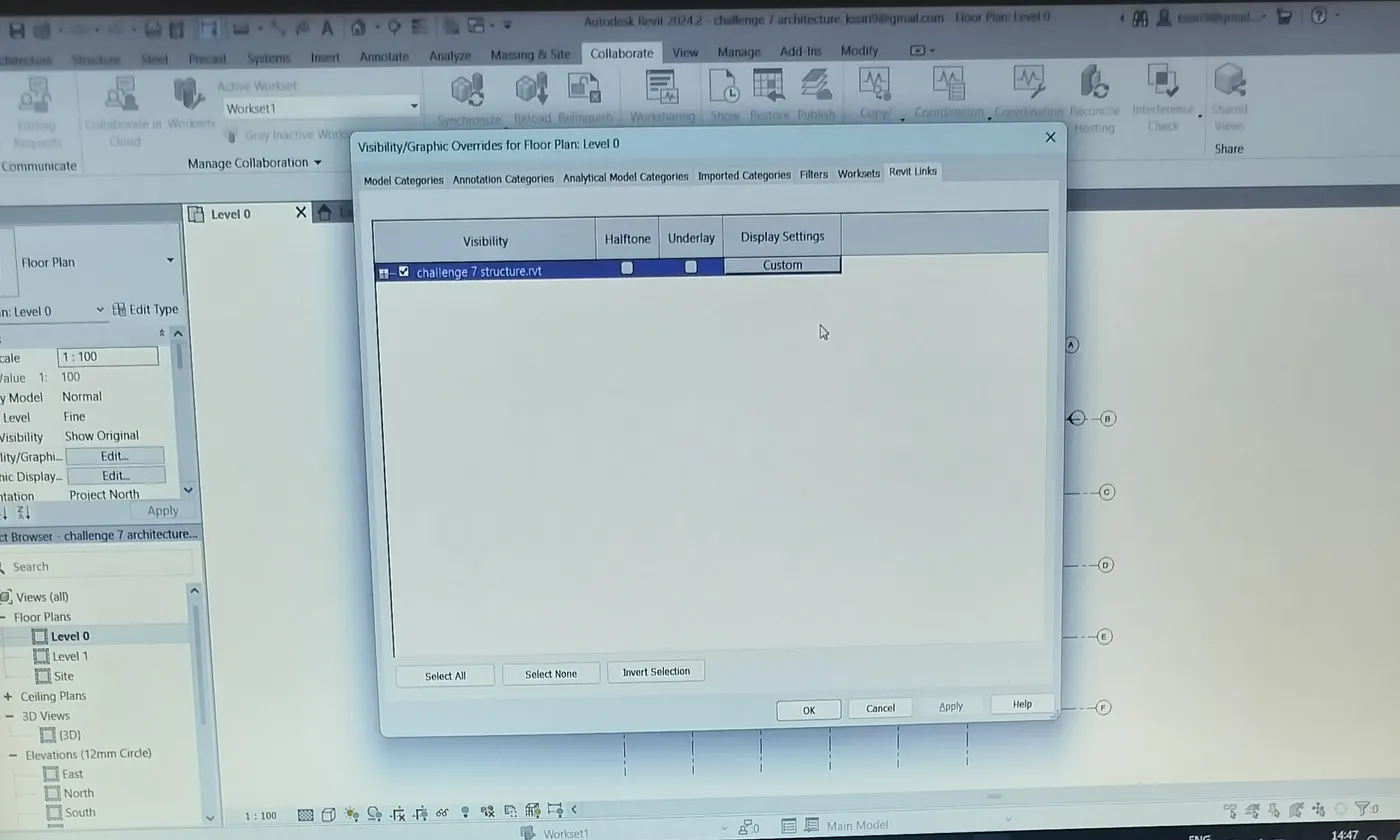
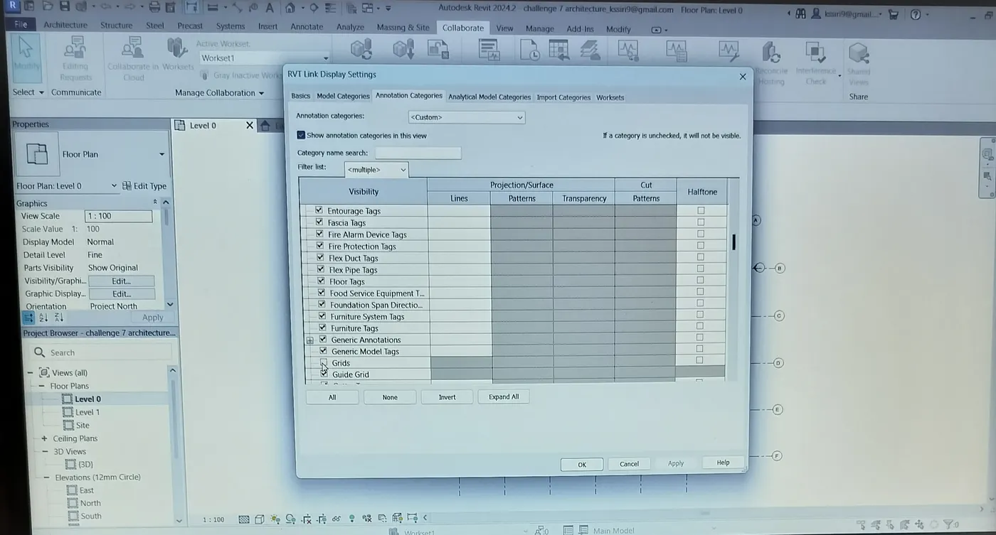
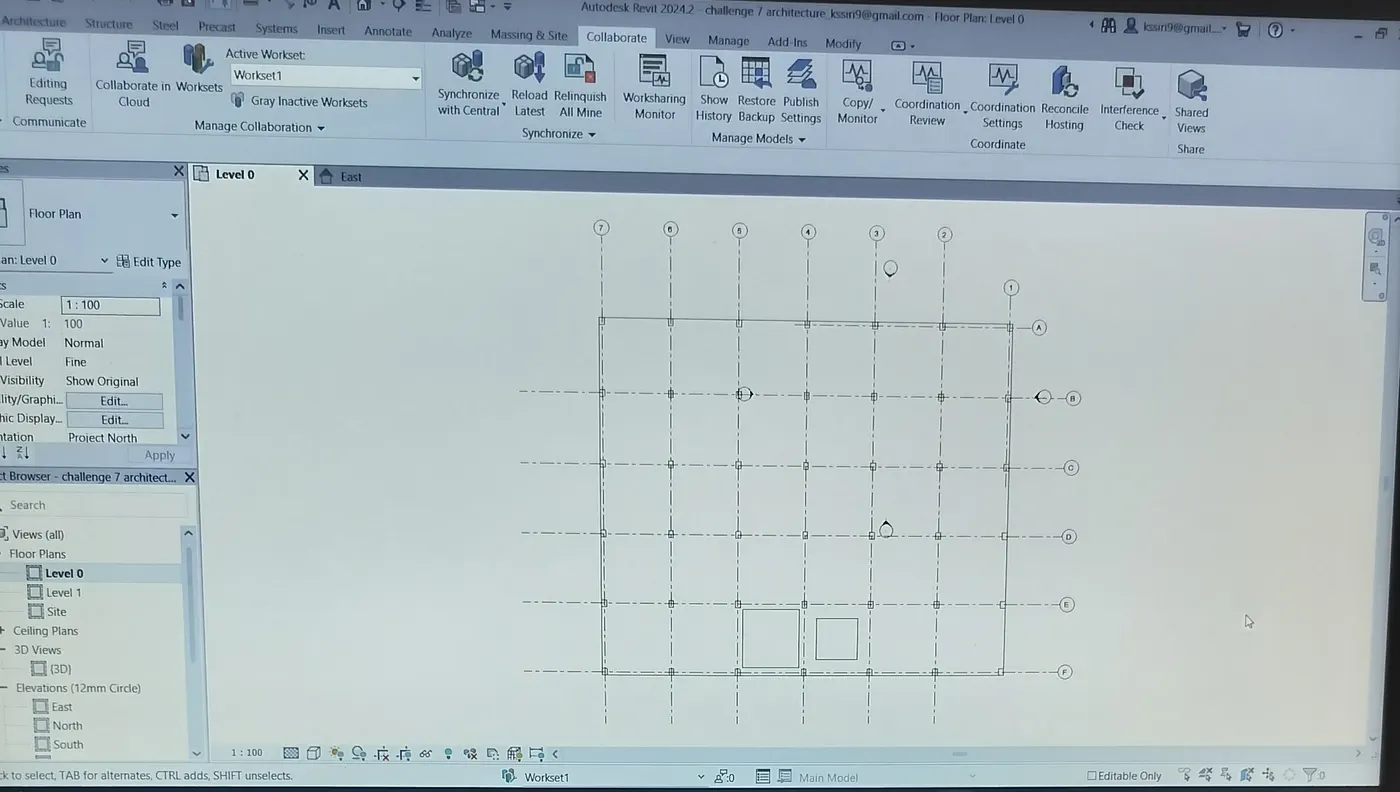
Select the elevation view. Select copy / monitor from collaborate tab and select link. Now click on copy , select the levels and then click on finish. Now go to visibility/graphics setting and select custom in revit link. Click on annotation categories in revit link display settings and select custom. Deselect levels and click on apply and ok. We can see that only levels from architecture model are present.
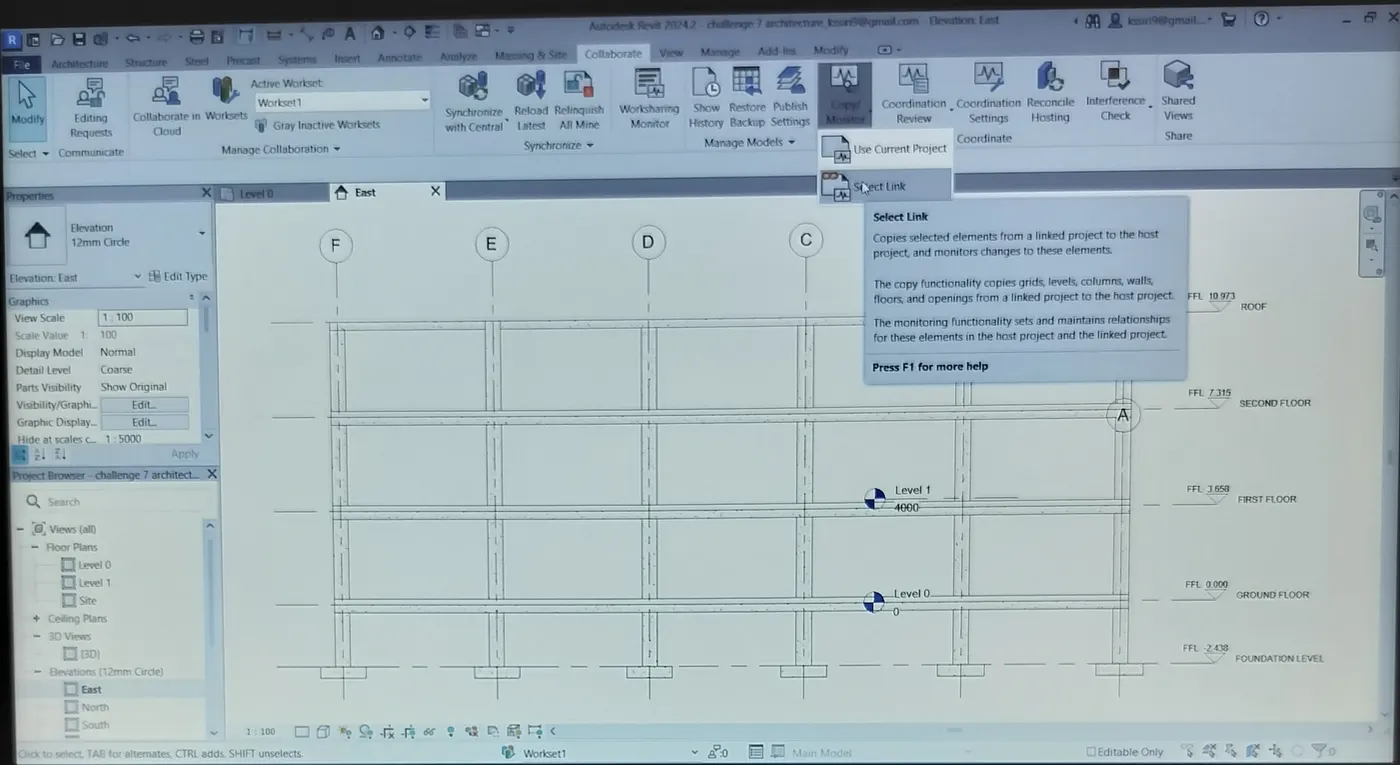
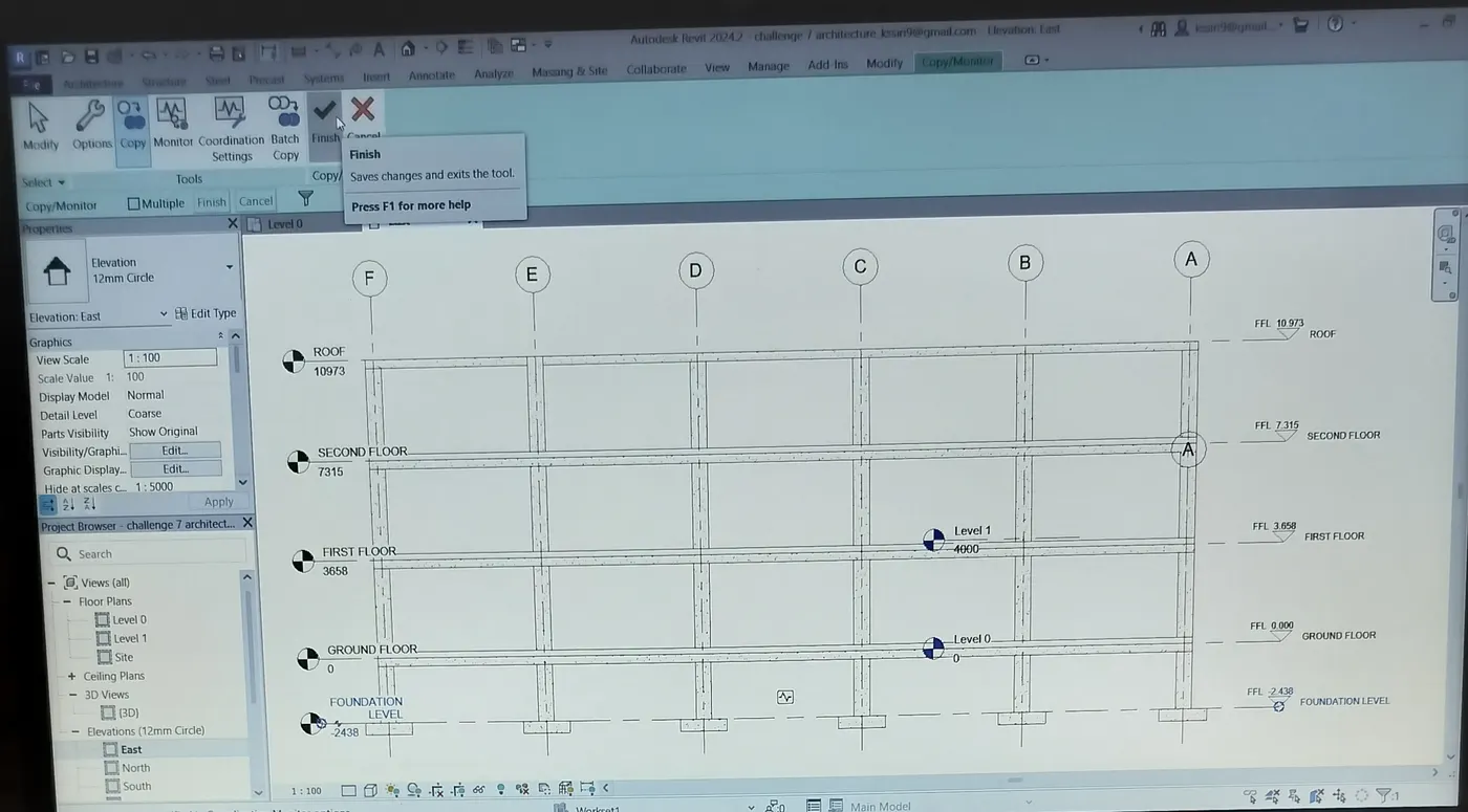
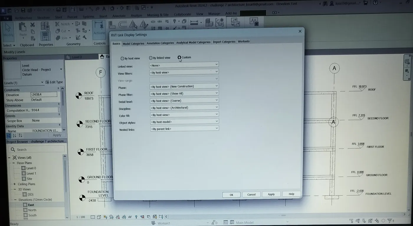
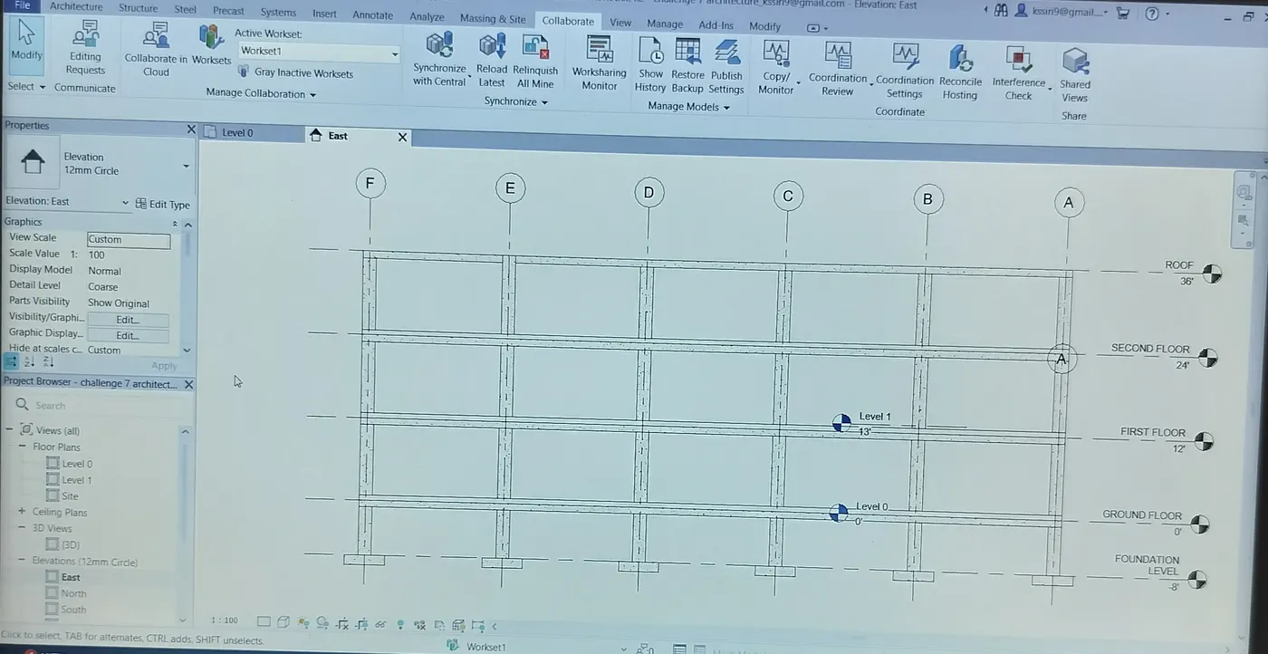
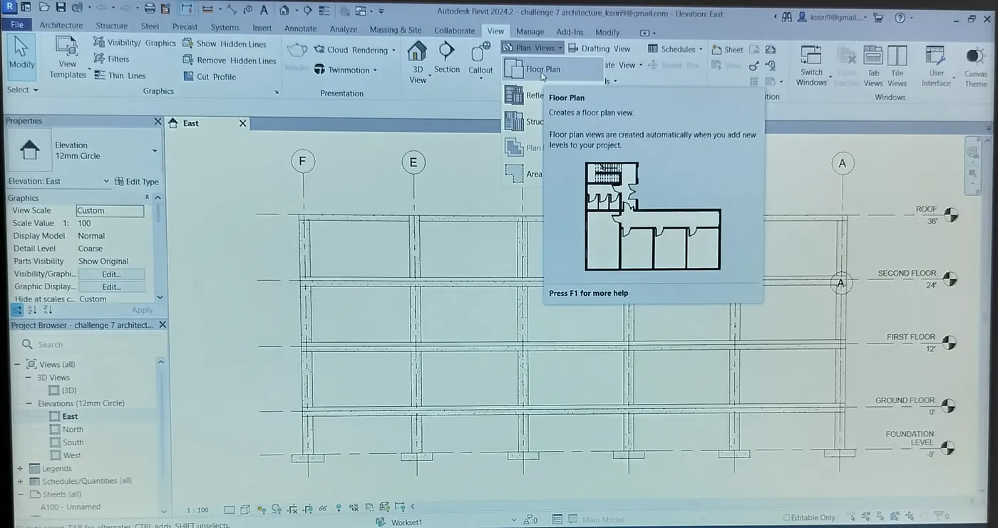
Now delete level 0 and level 1 from the elevation view. We can observe that floor plans in project browser are also removed. Now select plan views from view tab and select floor plan. A dialogue box will appear asking for which plans you want to create . Select different floor plans and click ok. Now we can observe floor plans in project browser.
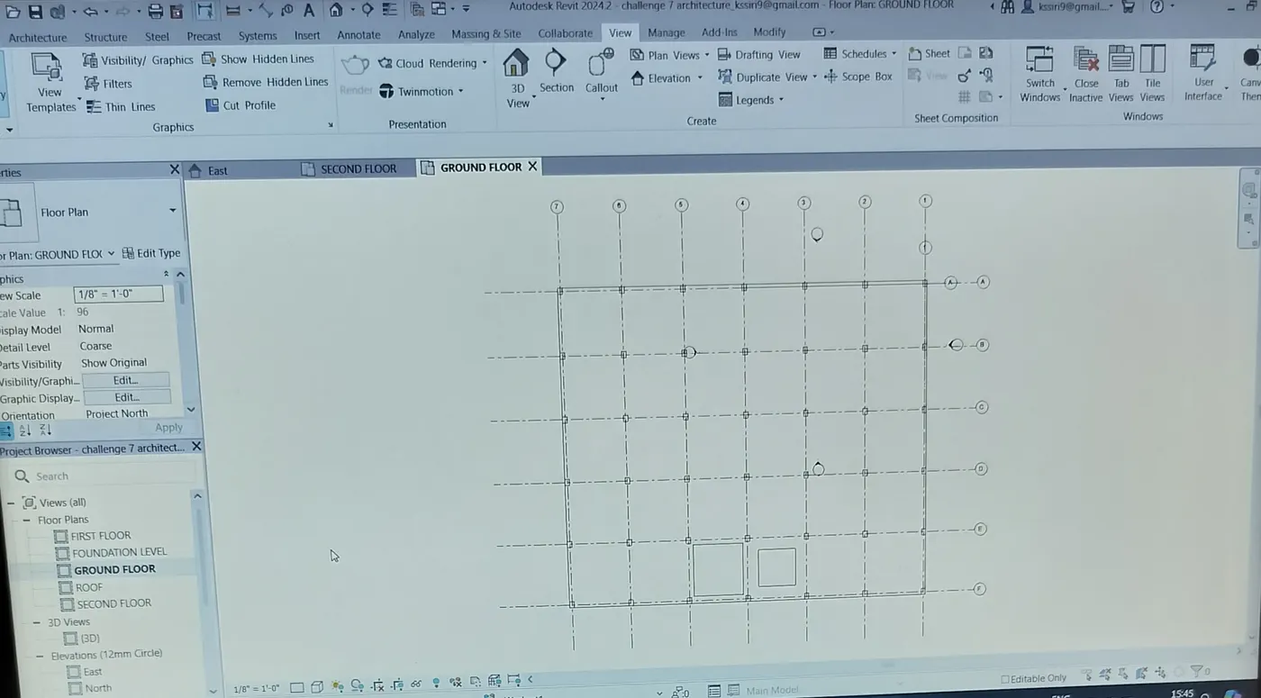
Open ground floor plan. Select walls in the architecture tab and select type of wall in the properties. Now click on line or pick lines to draw walls around the columns . We see that exterior walls are formed. Go to properties and select upper constraint so that walls will be formed till that level. Now change the exterior wall at the stairs and elevator as curtain wall.
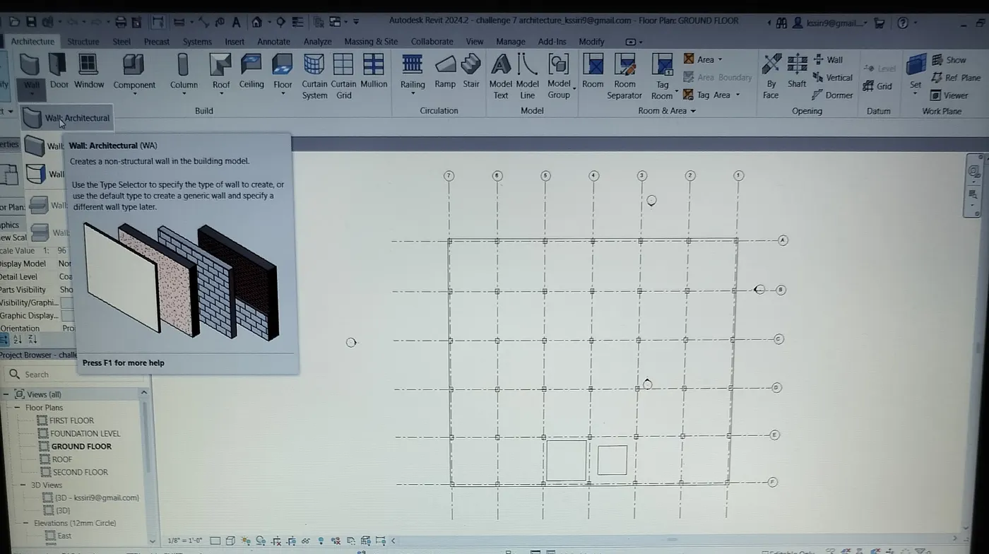
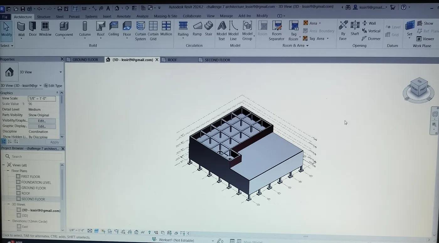
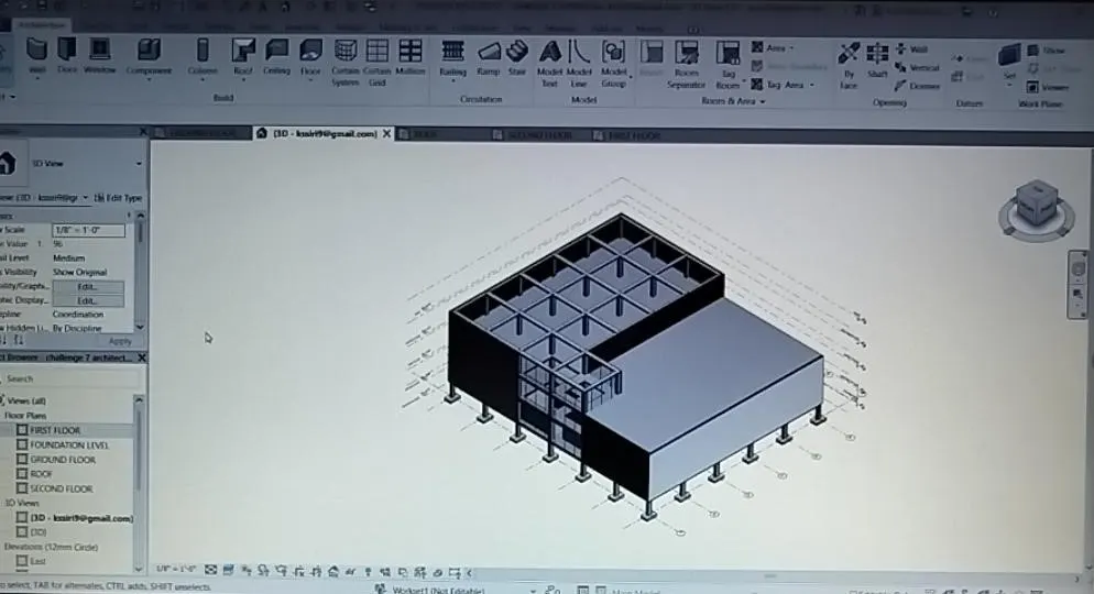
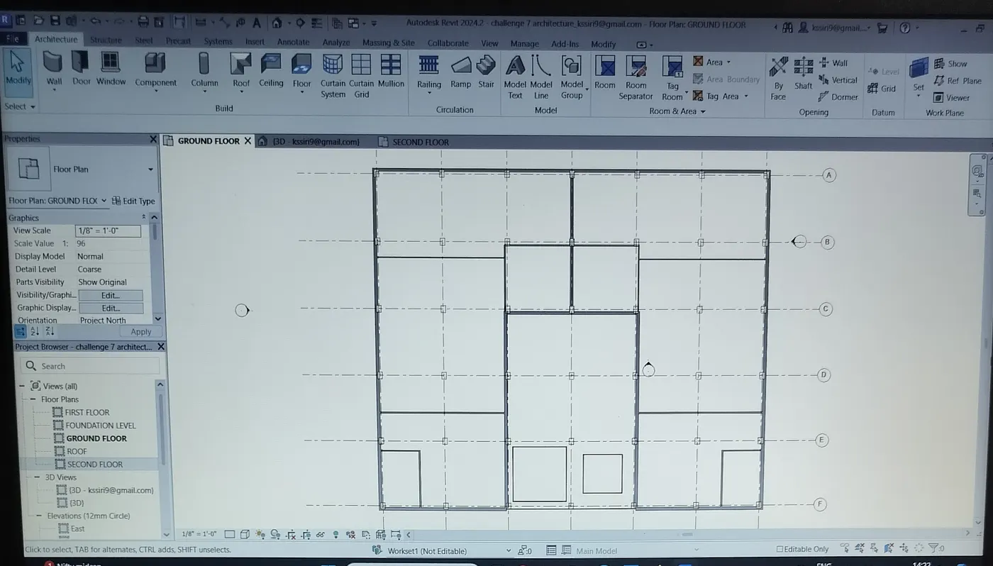
Draw interior walls or partition walls for bedroom, living room, kitchen, washroom ,etc.. Also add doors and windows to the architecture model.
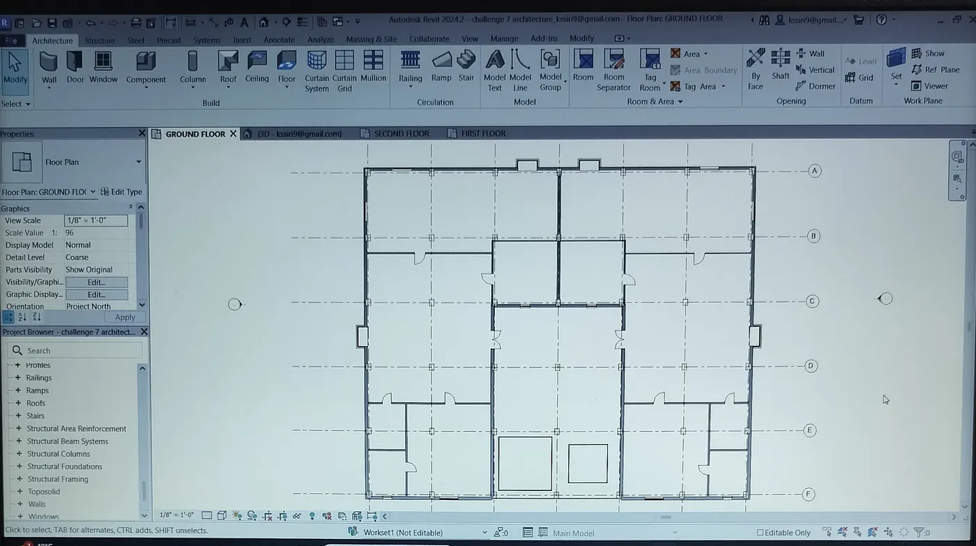
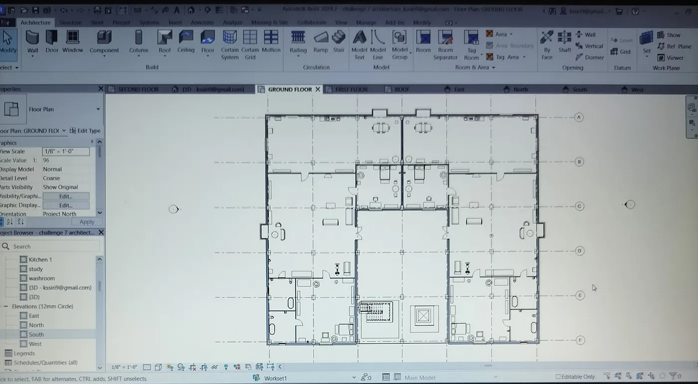
Place different details such as sofa, plumbing fixtures, bed, etc. as required in the rooms by loading autodesk families.
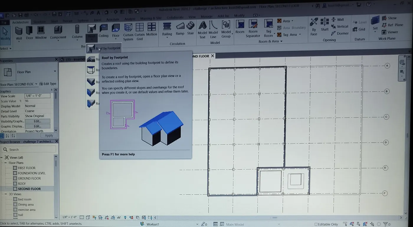
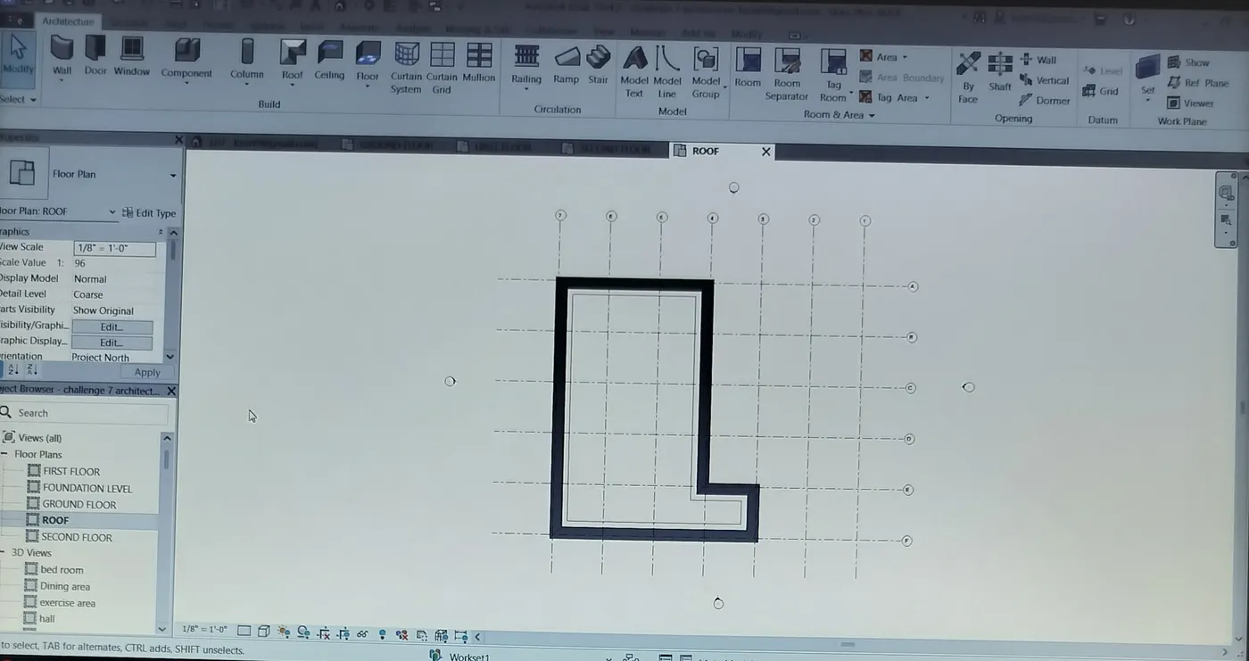
Open roof floor and select roof from architecture tab. Draw the boundaries and click finish.
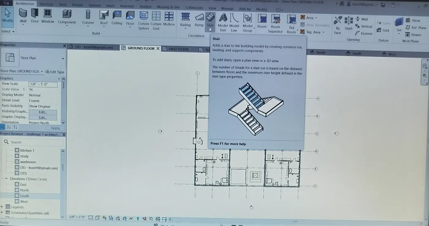
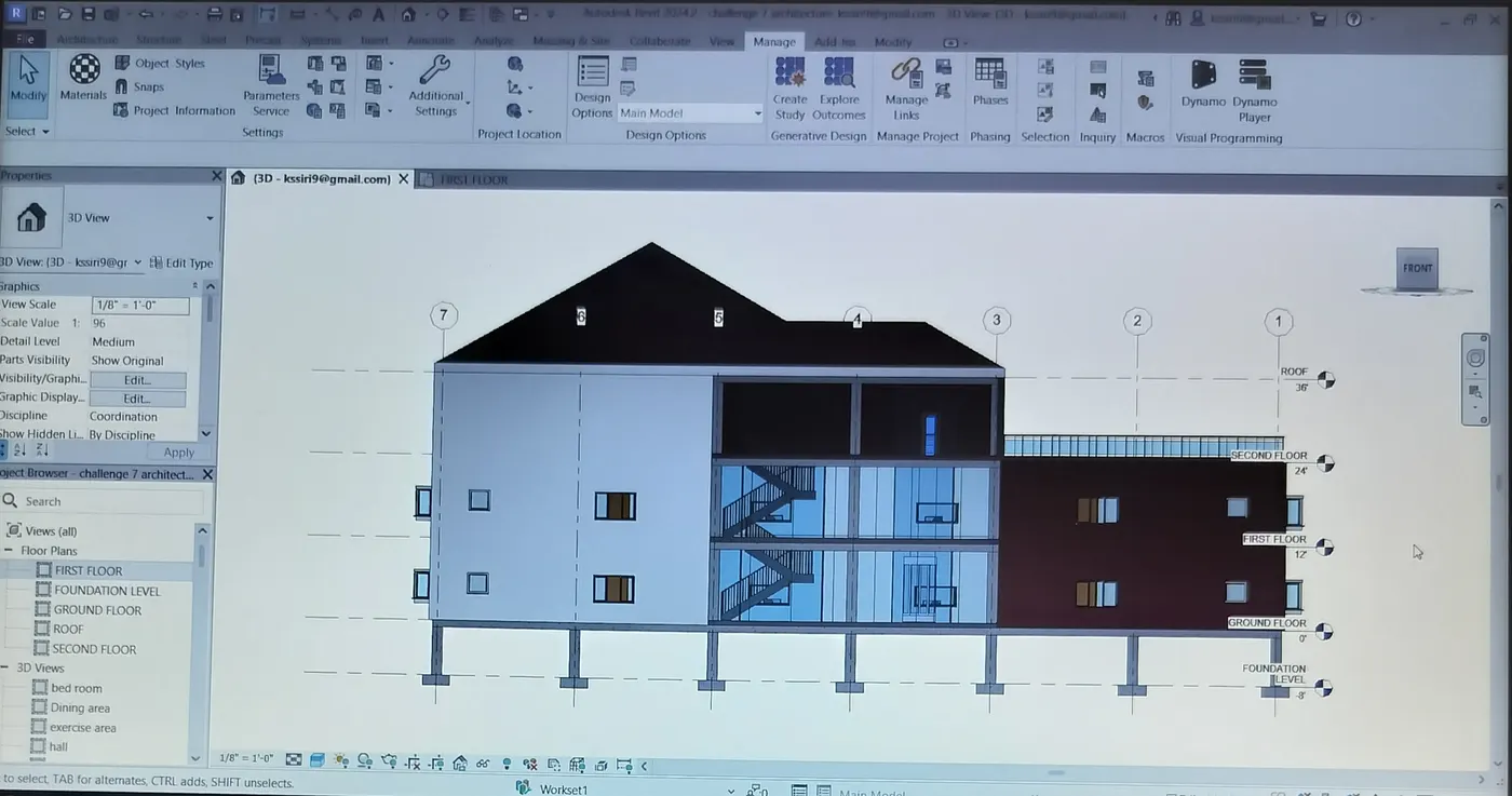
Open ground floor. Select stair from architecture tab. Click on type of stair case you want and click where you want in the ground floor plan. Click finish.
Open foundation level. Select toposolid option from massing and site tab. Select boundary line and click on ok. Now add site components like trees, parking, etc.
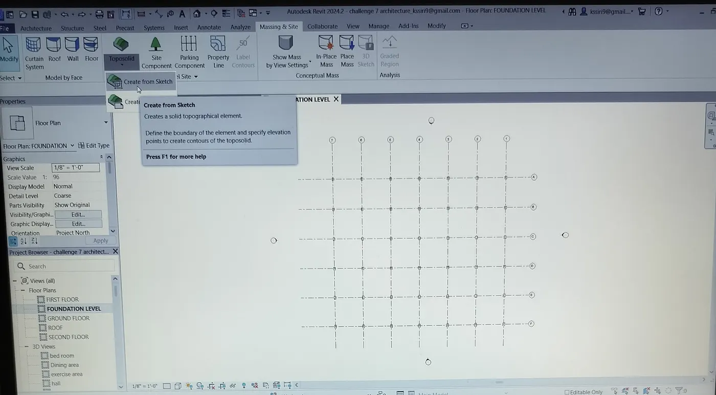
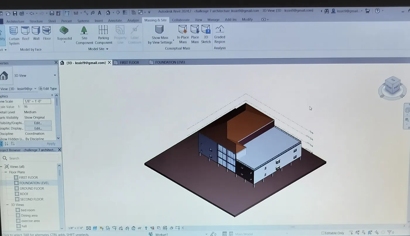
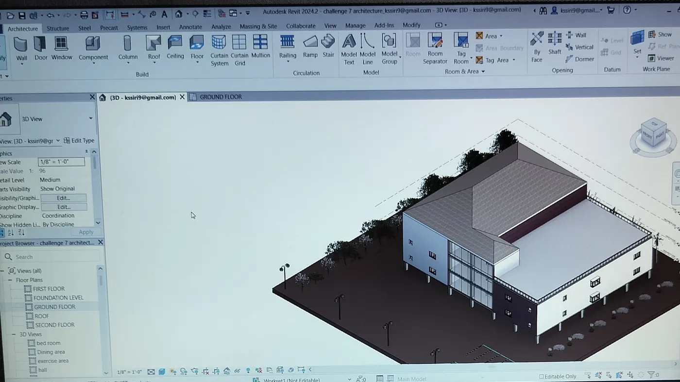
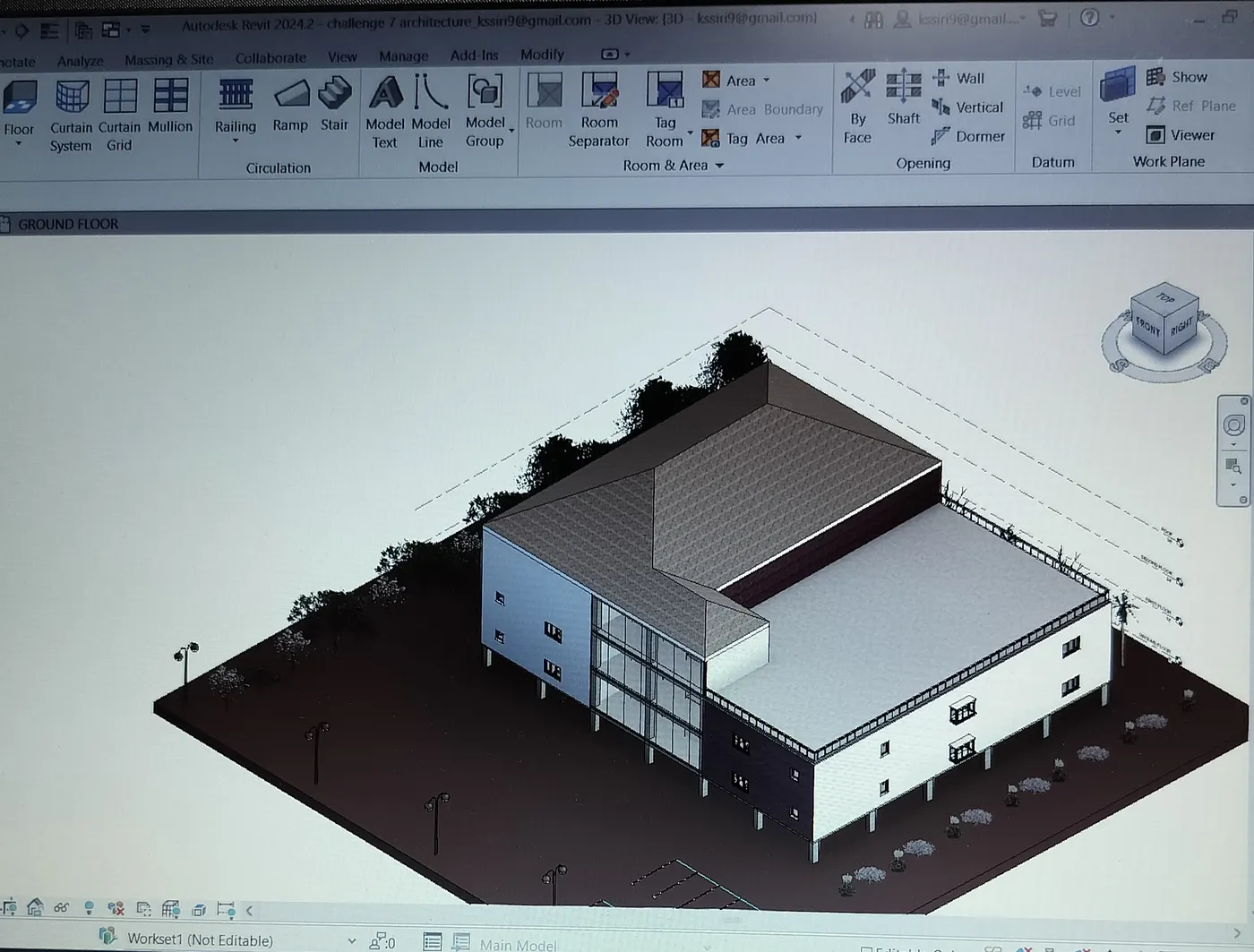
Result : Completed the architecture model with architectural elements like walls, doors, windows, furniture , etc.
5) Aim : To provide set of drawings from architecture and structural model in the form of sheets.
Introduction : A sheet of a drawing is provided to produce it to the customer /client , so that they will get an idea of the plans or different views or elevations without seeing the drawing.
Procedure :
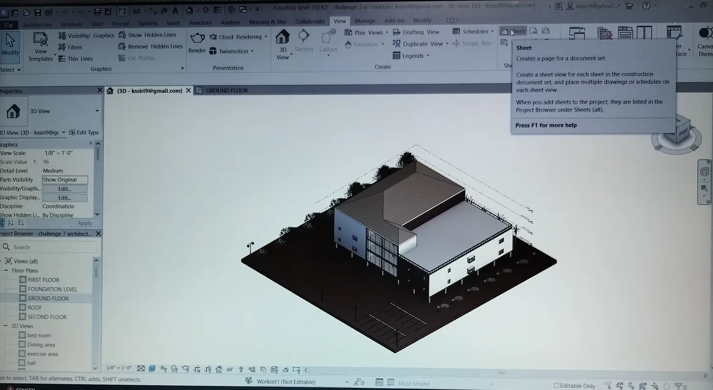
Open the architecture model .Open the view tab and select sheet . A dialogue box with new sheet will appear and click on ok.
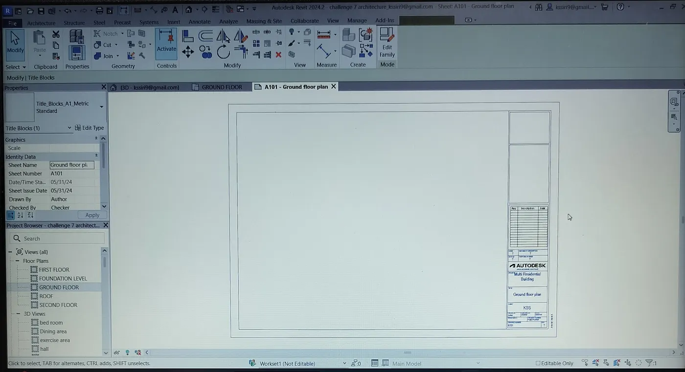
A sheet will appear .Now edit all the details which you want in the sheet.
Now add different floor plans or elevations or sections in the sheet from view in view tab.
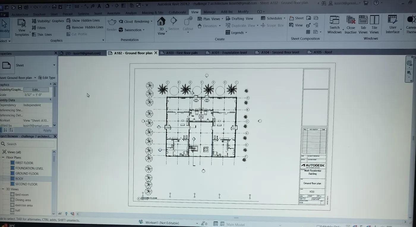
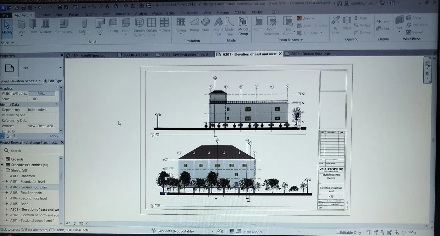
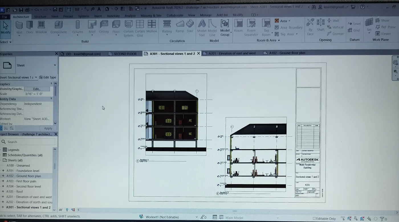
Now similarly open the structure model and follow same procedure as above and create sheets.
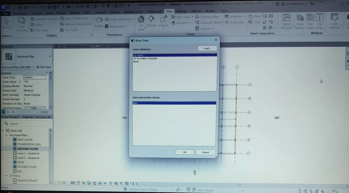
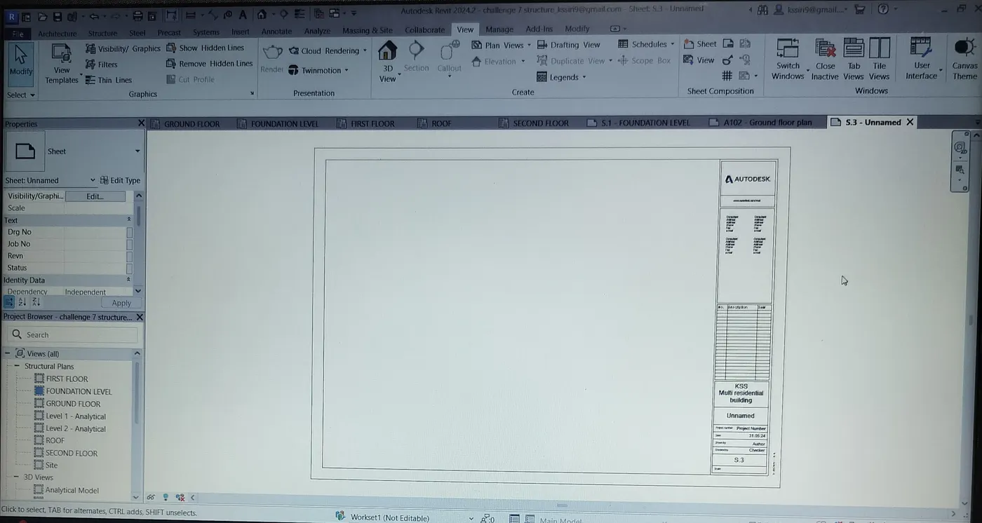
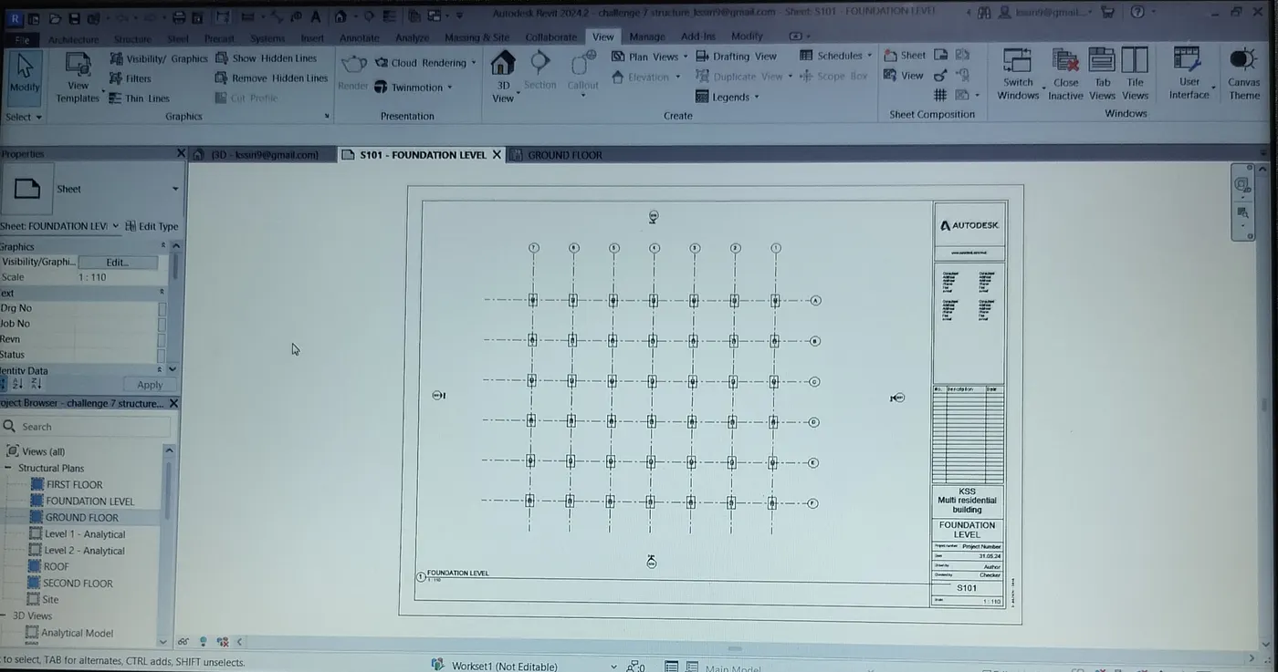
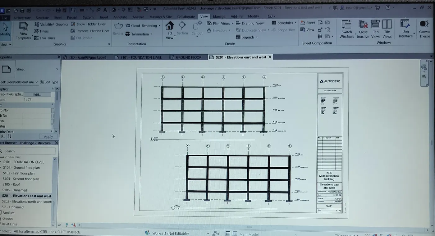
Result : We observe different sheets with plans / sections / elevations from both architecture and structure model.
6) Aim : To render images of the 3d model.
Introduction : By rendering images we can get photographic effect while using different settings like type of light etc.
Procedure:
Open the architecture model and open ground plan. Click on 3d view and select camera in view tab.
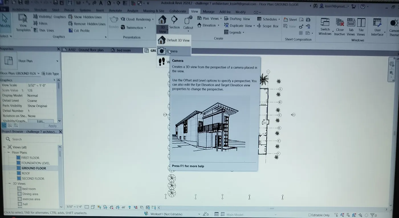
Now use camera in any room which you want so that we can see the 3d view of the room i.e. , furniture we placed in that room. Now open any 3d view which we created. Select render in the view tab and click on it.
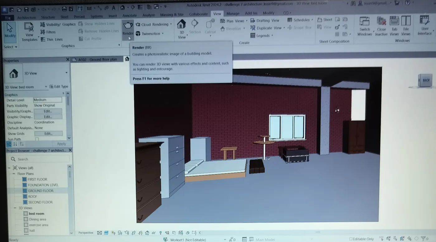
A dialogue box will appear in which we can change the parameters and click on render.
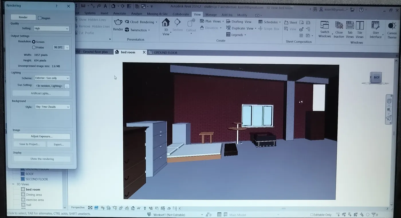
After completion of rendering process, we can see render image of the 3d view.
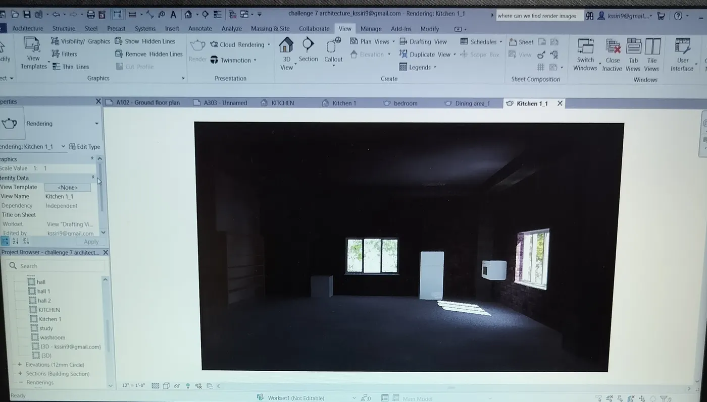
Similarly we can render any 3d view in both architecture and structure model.
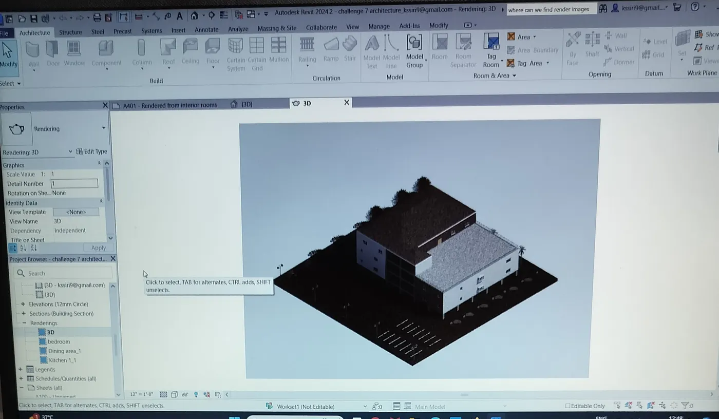
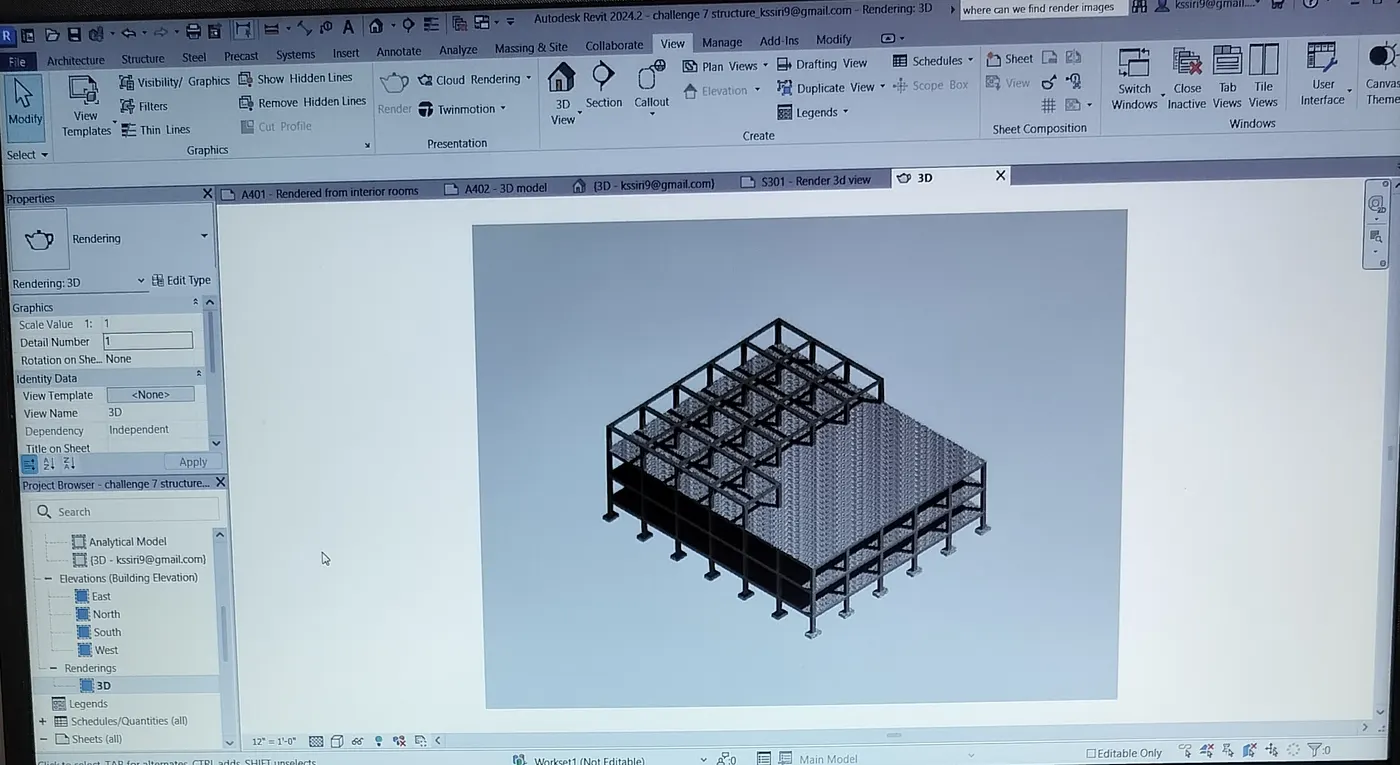
After rendering both structural and architecture model we can place them in sheets.
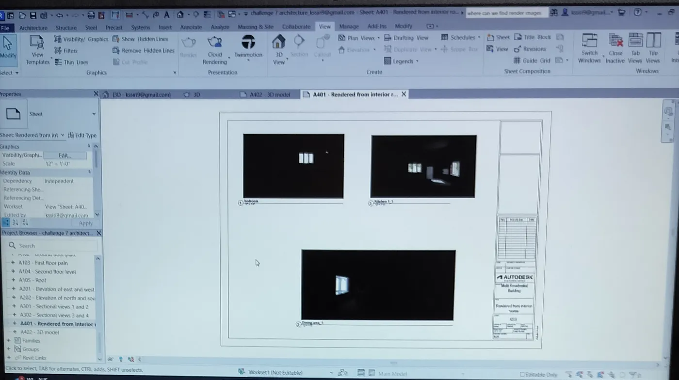
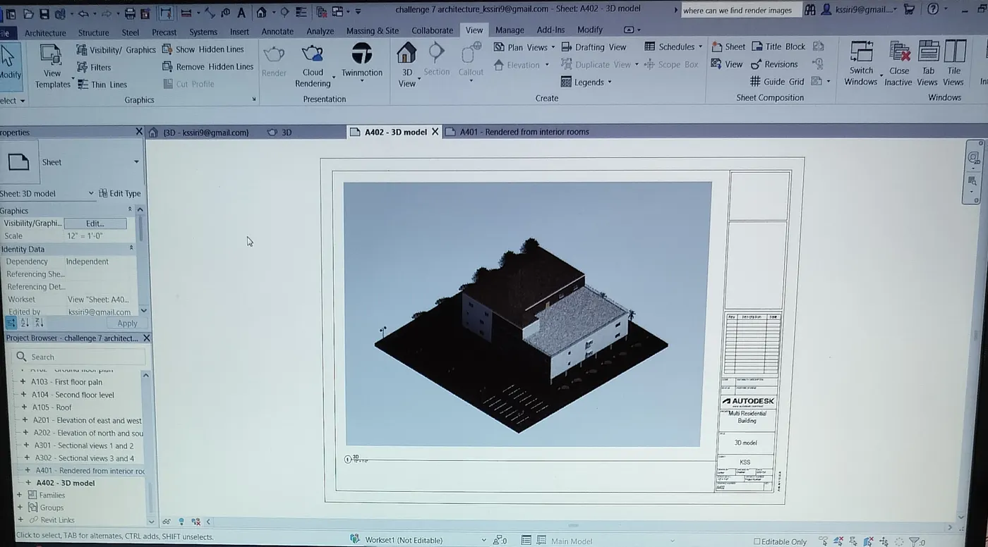
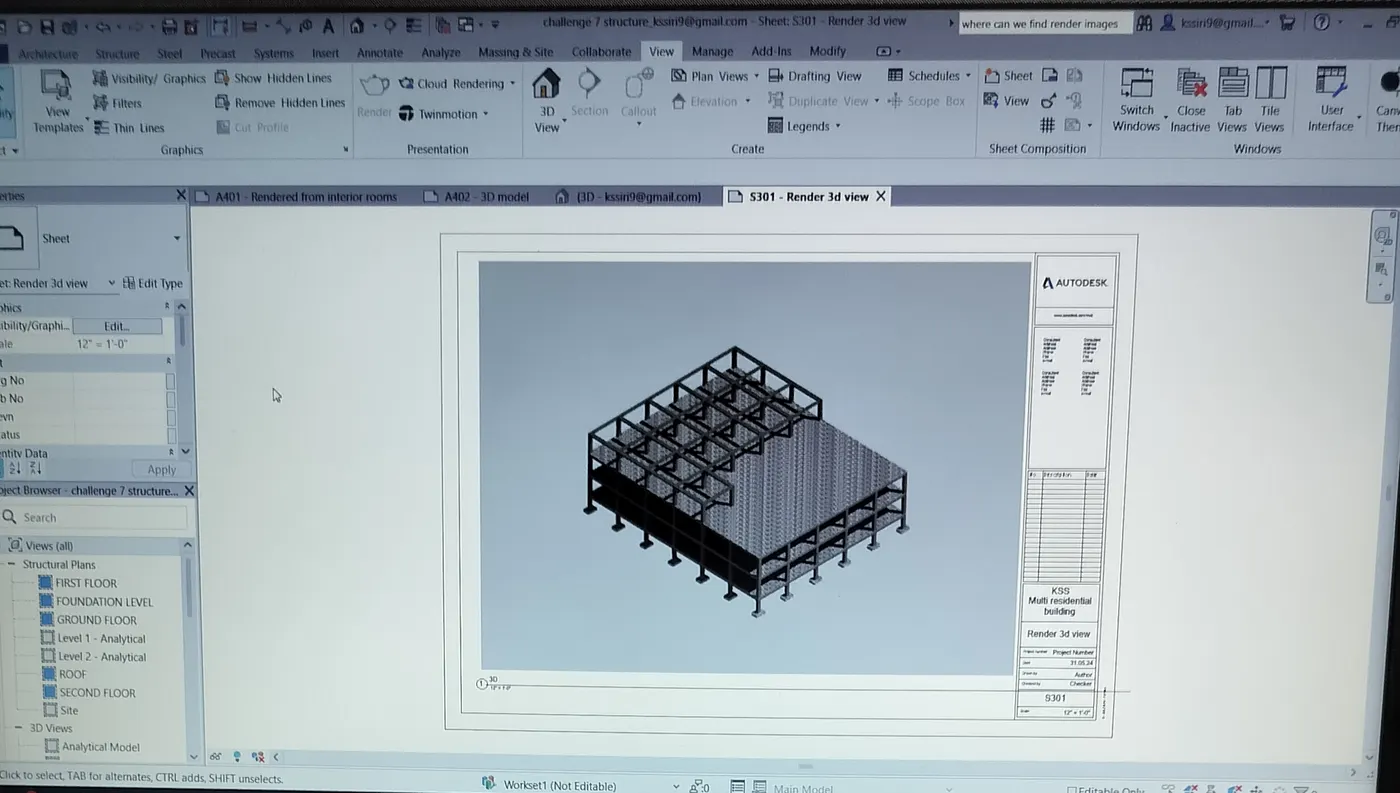
Result : In both architecture and structure model we can see both render images of different 3D views.
7) Aim : To print sheets of both architecture and structure model.
Introduction : To print sheets so that they can be used in site.
Procedure : Open the sheets which we created both architecture and structure model.
Press Ctrl + P and change the settings options as you want to print the sheets or save them as pdf so that you can print them whenever required.
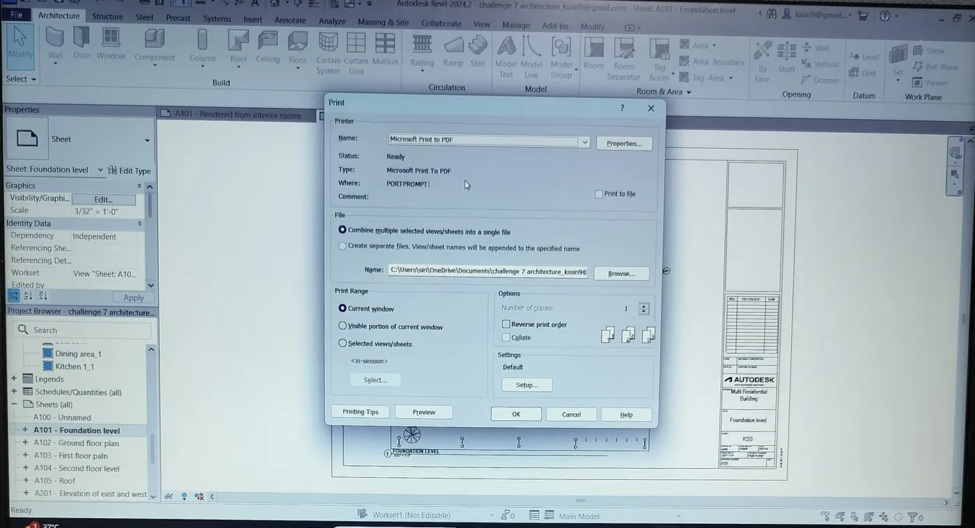
I am attaching two pdf files which i have saved.
Similarly we can create pdf for all sheets.