Project 1
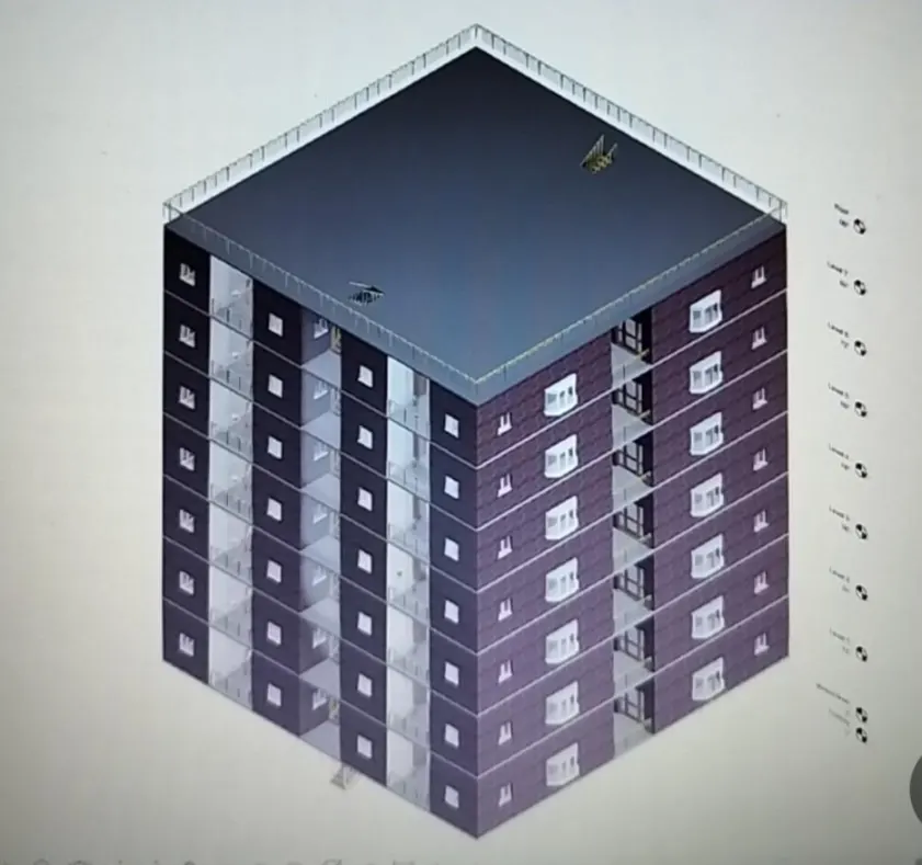
Aim : To model an apartment of 4 units on each floor of 7 storeys.
Introduction : To model an apartment with 4 units on each floor with different elements.
Procedure : Launch revit software .
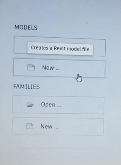
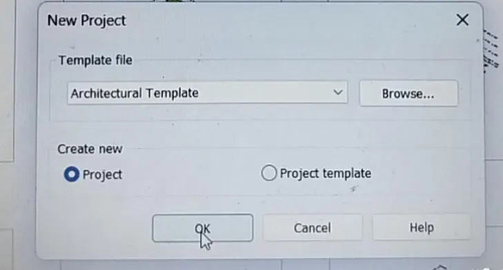
Click on new and select architecture template. click on ok.
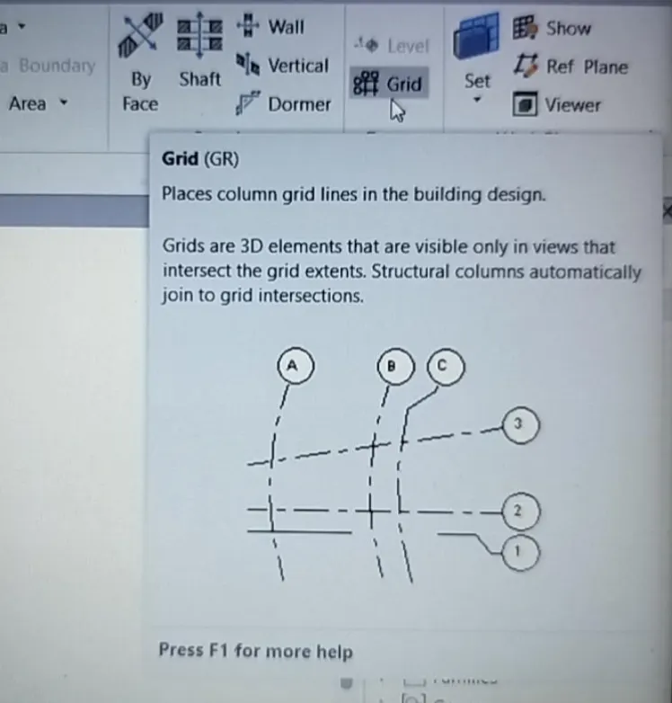
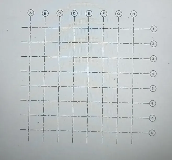
Select grid present in architecture tab and click on it. Now draw grids from one side to another and rename them as you wish. Similarly draw grids in another direction and rename them.
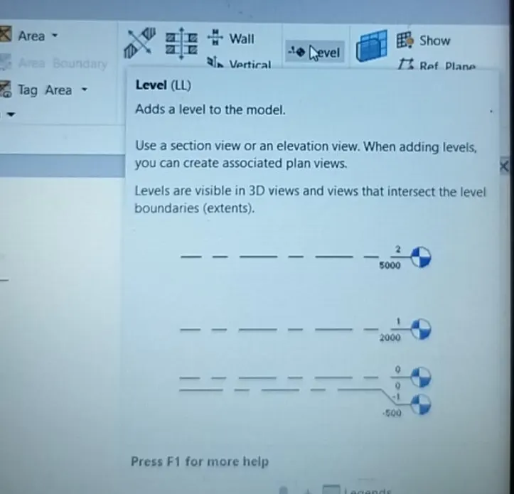
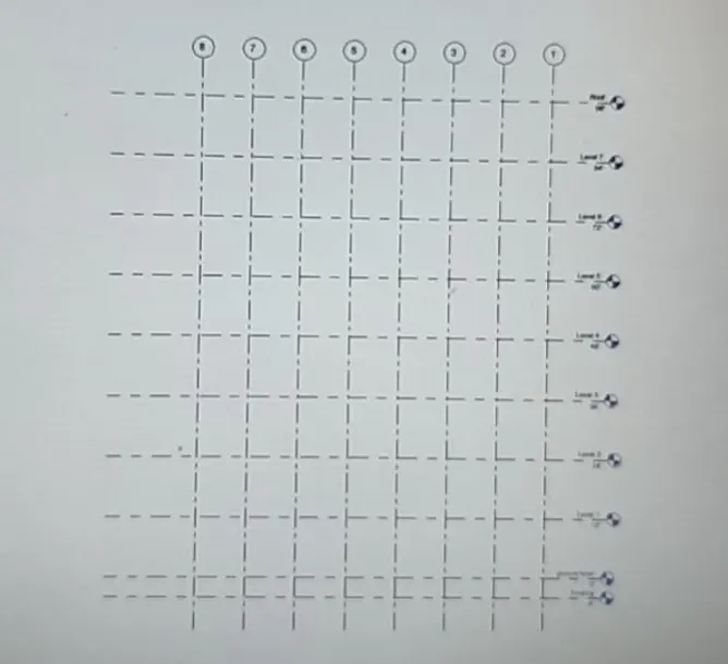
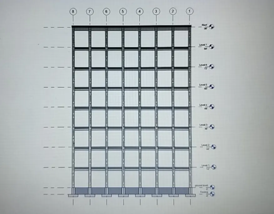
Go to elevation view present in project browser. Now draw levels by selecting on levels present in the architecture tab. We can also change levels name and distance between each level.
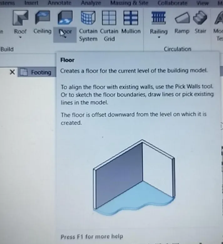
Open level 1 floor plan. Click on floor present in architecture tab. Draw boundary for the plan with excluding shaft openings and click on ok.
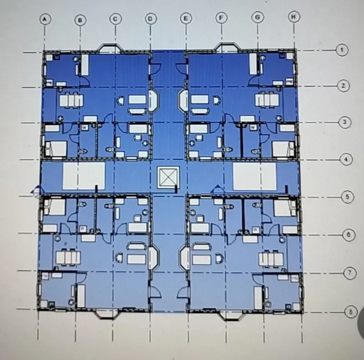
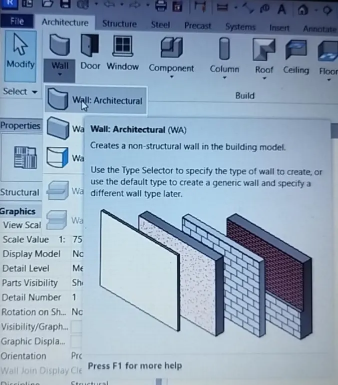
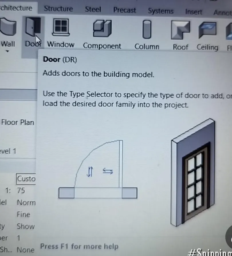
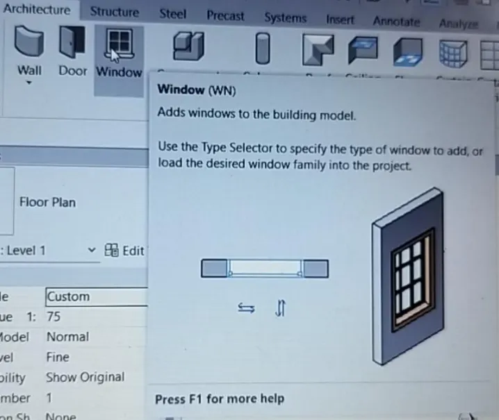
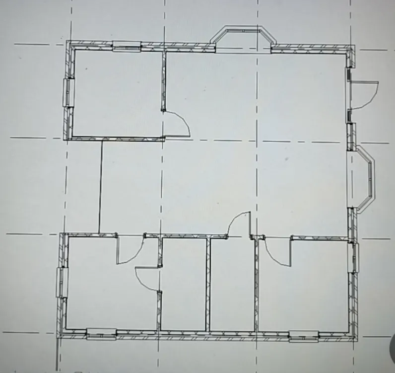
Select any floor plan present in the project browser. Click on wall present in the architecture tab. We can draw walls both exterior and interior so that rooms are created. Select doors present in the architecture tab and add them to the walls wherever required. Similarly add windows to the walls.
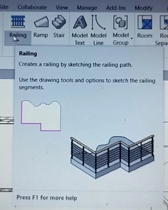
Click on railing present in the architecture tab and add it for any balcony or for external gazing so that no one will fall.
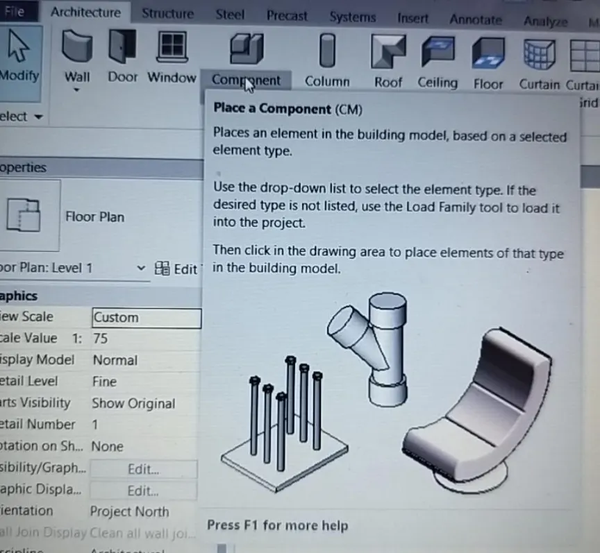
Add furniture to all rooms as required by clicking on component present in the architecture tab.
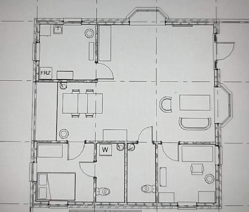
Now copy and mirror one model apartment (one unit) so that there will be 4 units in each floor. Now copy all the 4 units in floor to other floors .
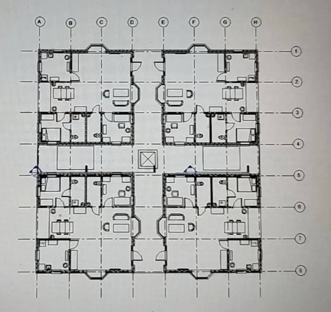
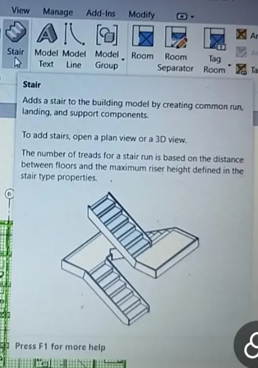
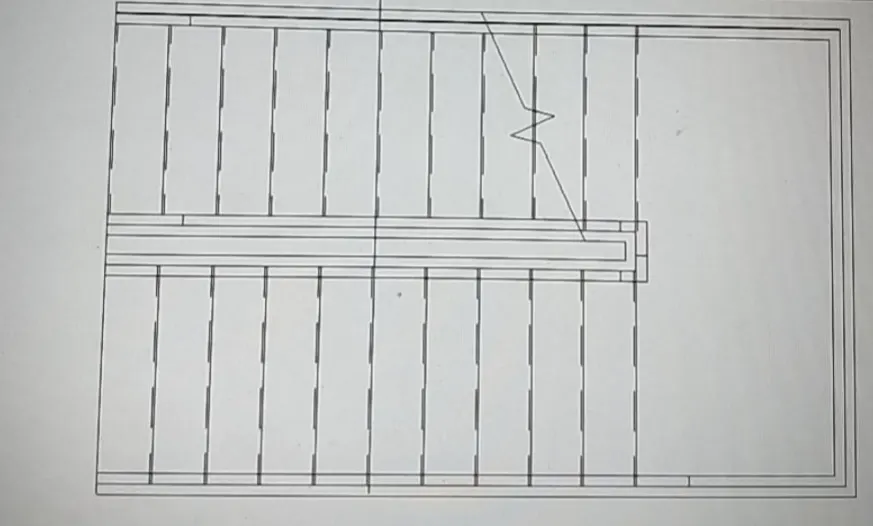
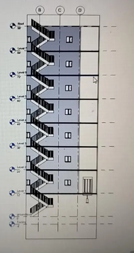
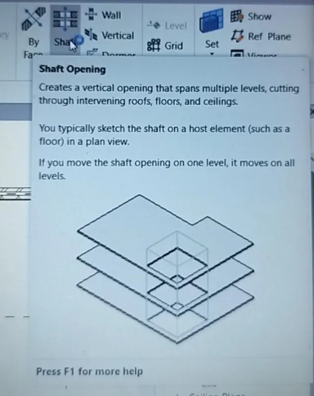
Add stairs by clicking on stairs present in the architecture tab. Also add shaft opening around stairs .
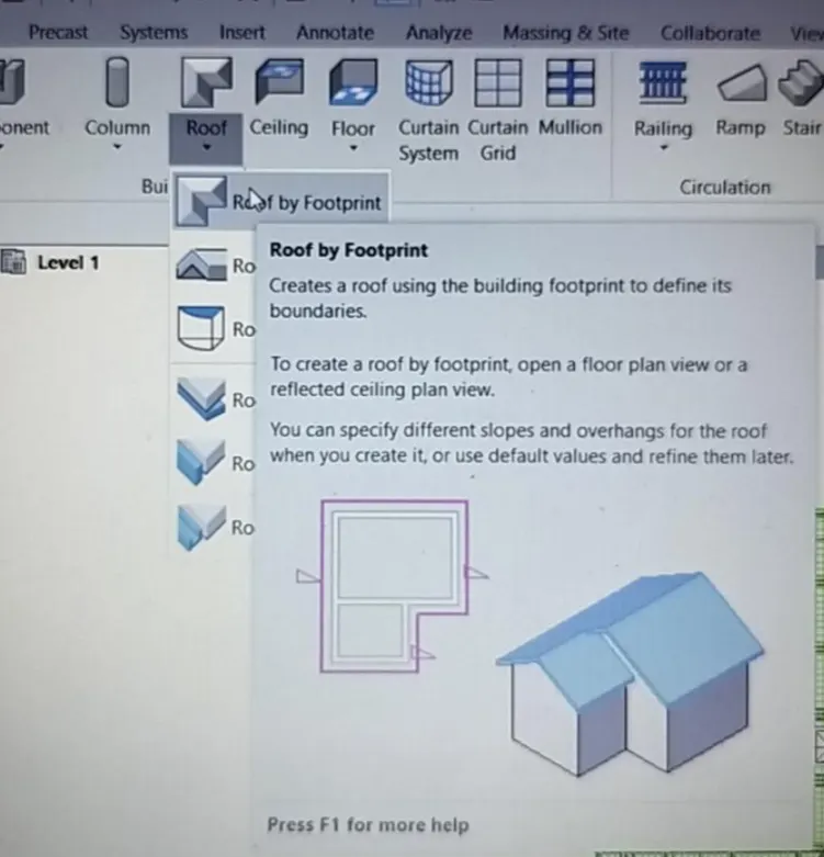
Open roof floor . Click on roof present in the architecture tab and draw boundary and click on ok. We can see roof of the building.
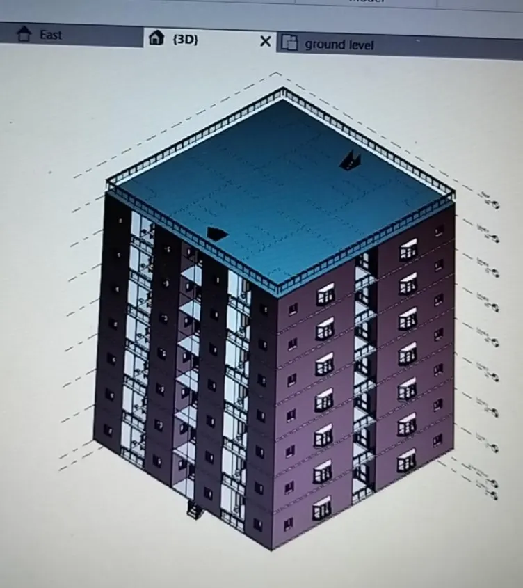
Architecture model of 7 storey building with each floor containing 4 units is ready.
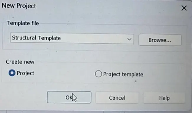
Click on new and select structure template. Click on ok.
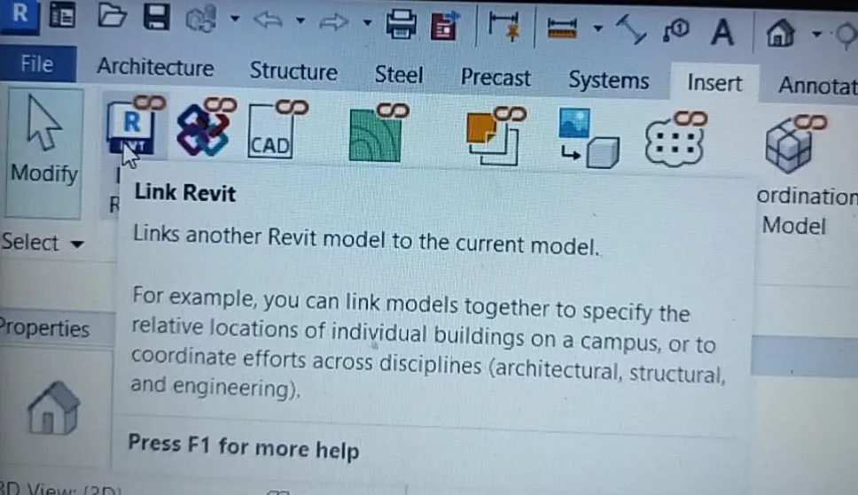
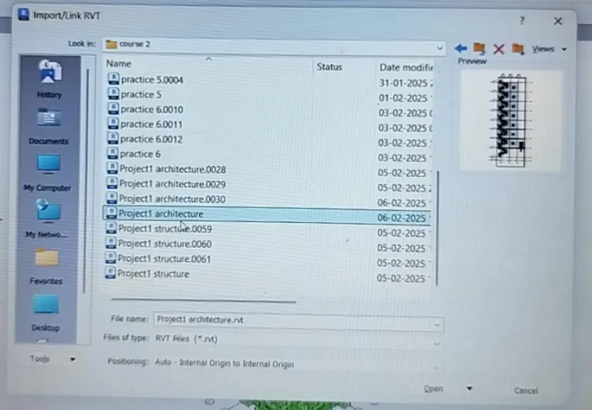
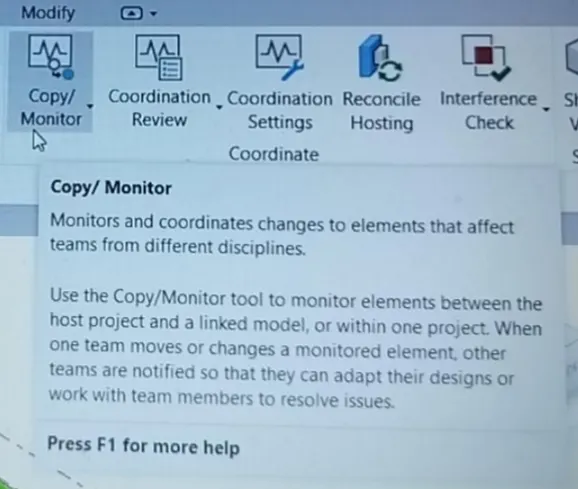
Now select link revit present in insert tab and link architecture file. Now copy grids of architecture file to structure file by using copy/monitor present in collaborate tab. Similarly copy levels of architecture file to structure file in elevation view.
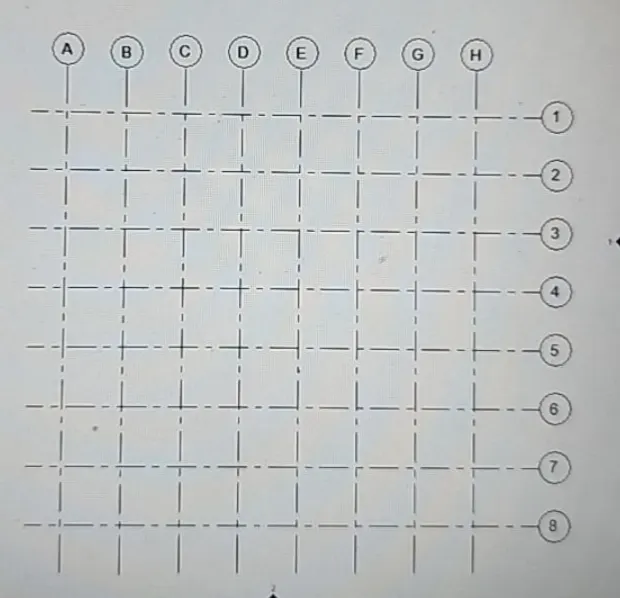
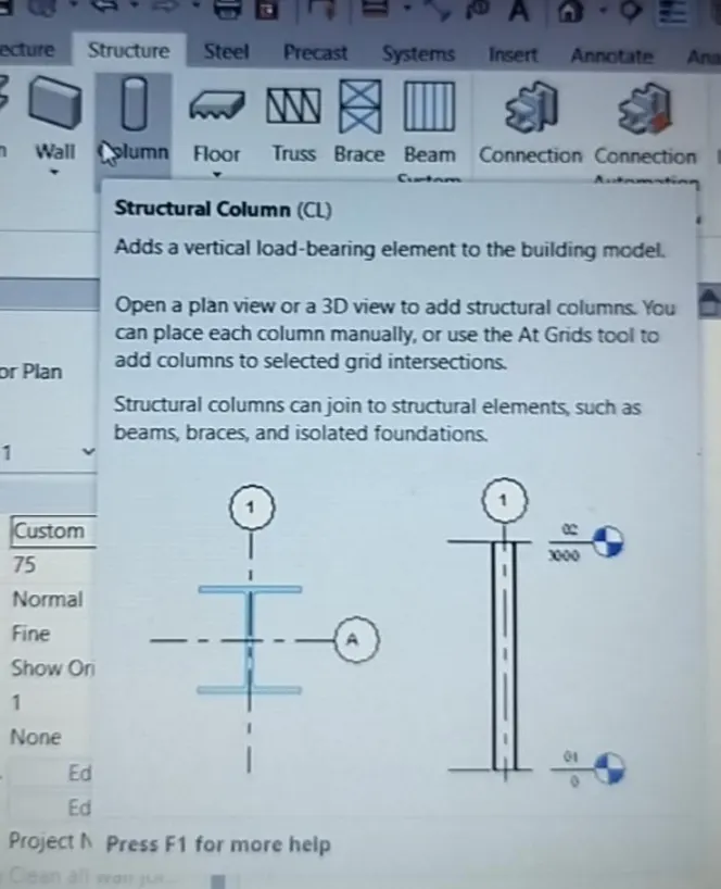
Open ground floor plan. Click on column present in the structure tab. Now select type of column and select at grids. By selecting all the grids we can see that columns are formed at intersection of grids. Also select from which level to which level we want column.
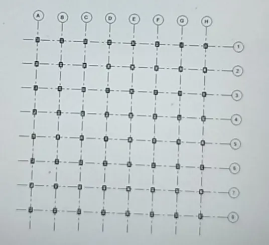
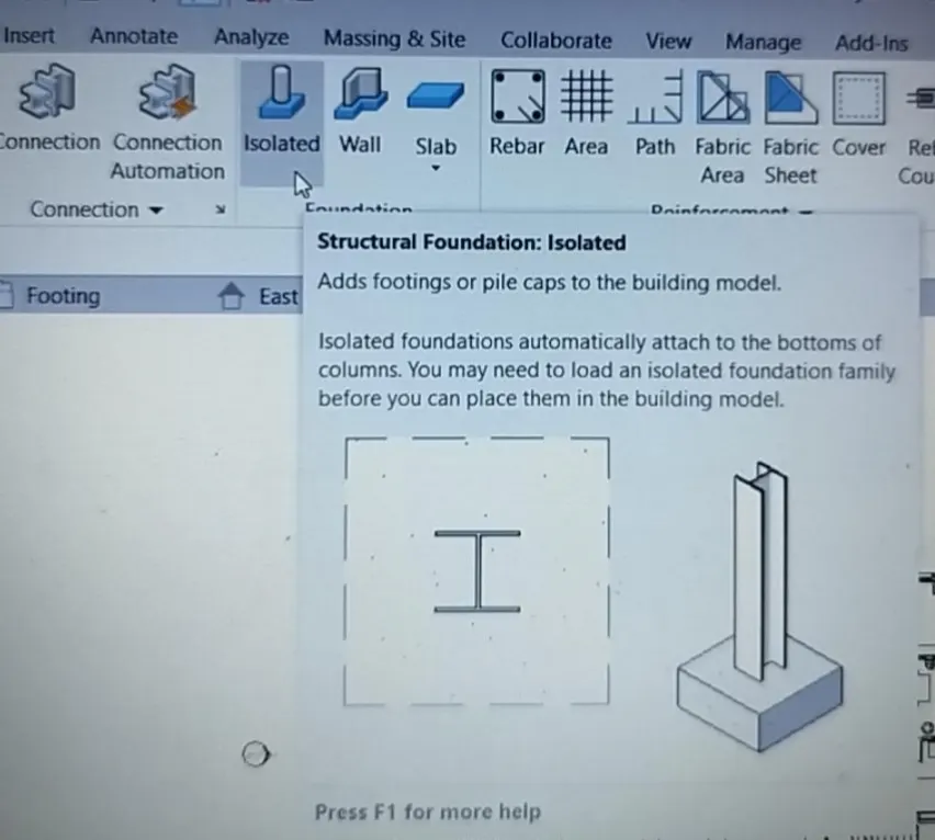
Open footing plan. Click on isolated foundation present in the structure tab. Now select type of footing and select at grids. By selecting all the grids we can see that footings are formed at the intersection of the grids.
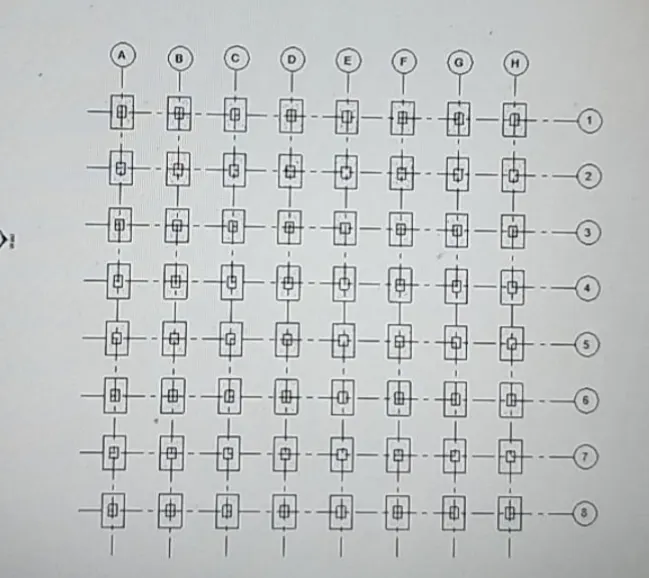
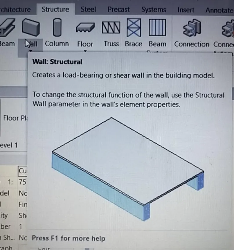
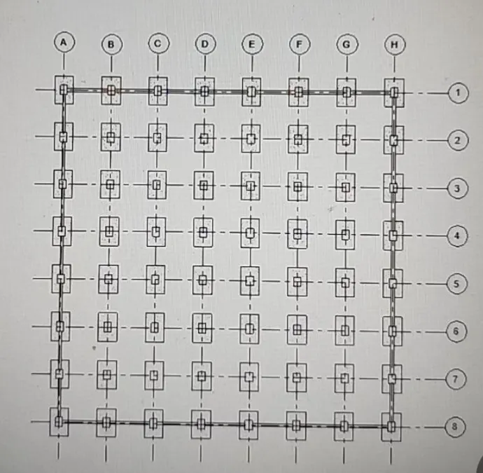
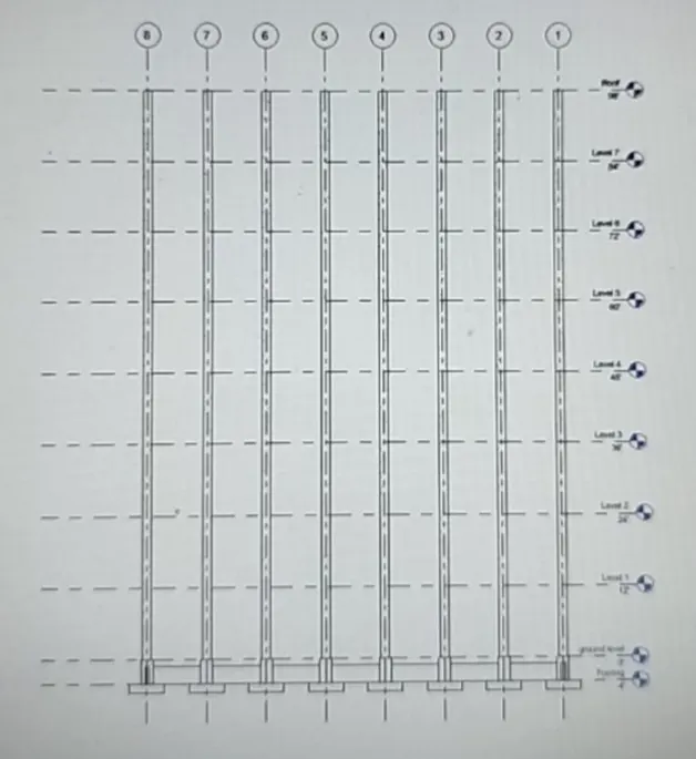
Open ground floor plan. Click on structural wall present in walls in structure tab. Also select the level from footing to the ground floor. In elevation view or 3D View we can see walls formed between footings level and ground floor level.
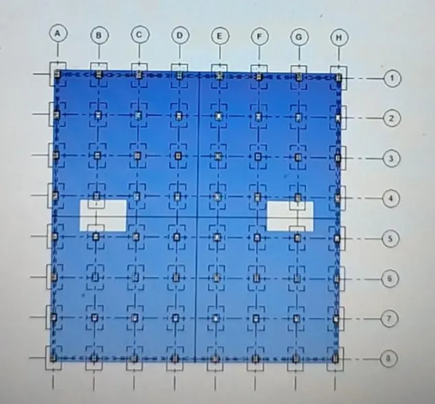
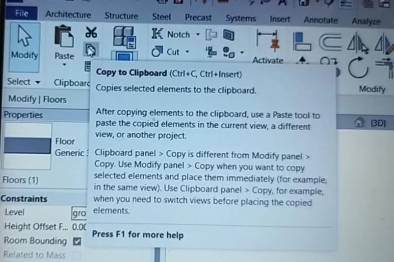
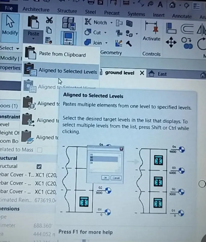
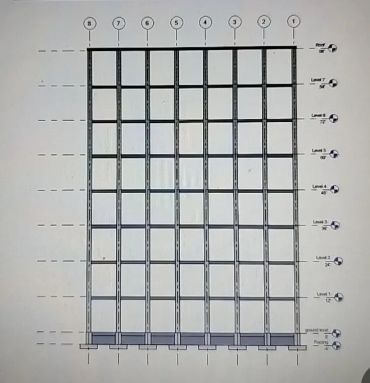
Open ground floor plan. Click on floor structural present in floor in structure tab. Draw boundary of the floor with excluding columns and shaft / stairs and click on ok. We can see floor formed in the ground floor. Similarly open level 1 floor and draw the boundary for floor and click on ok. Now copy floor of level 1 to other levels by clicking on copy to clipboard and paste to selected levels.
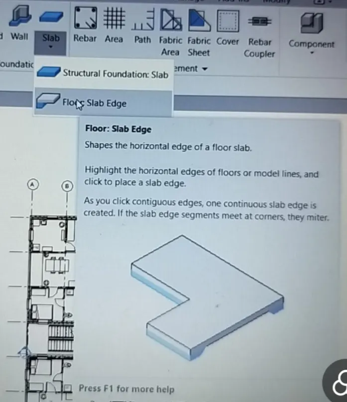
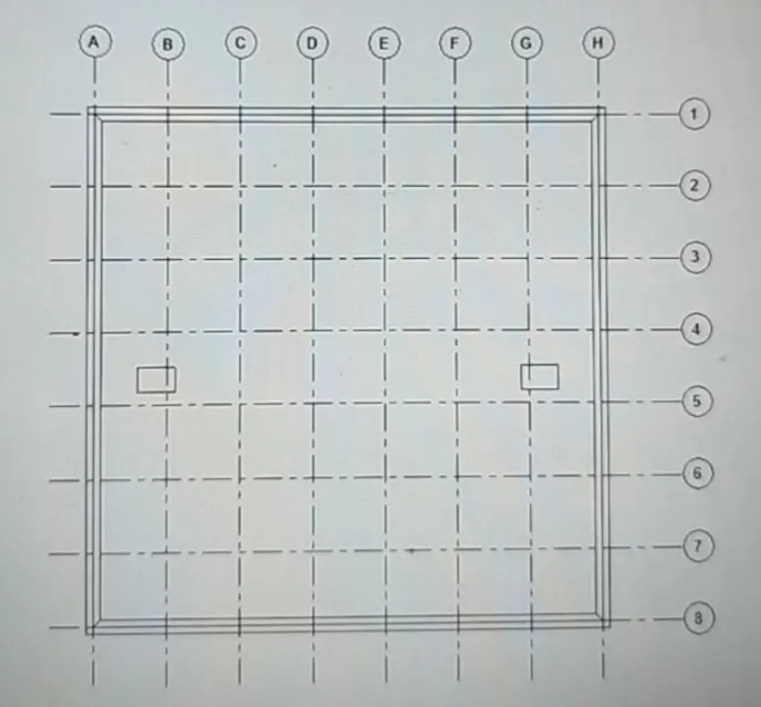
Open roof floor plan . Click on slab edge present in the floor in structure tab. Click on the floor and we can see slab edge is formed around boundary of the roof floor.
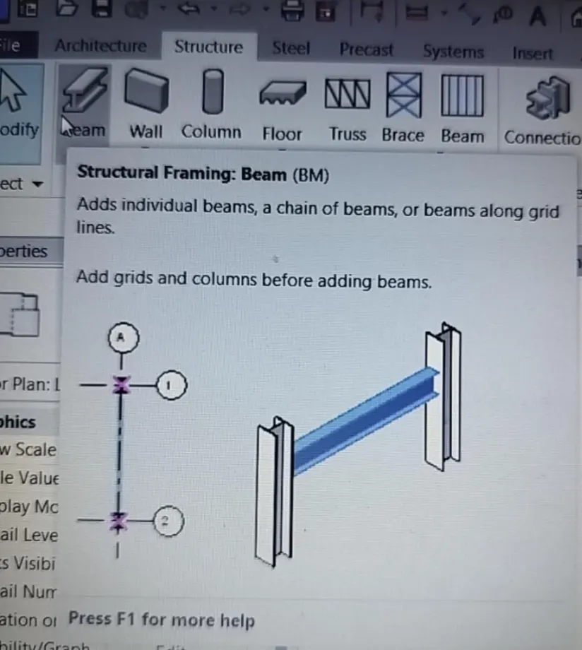
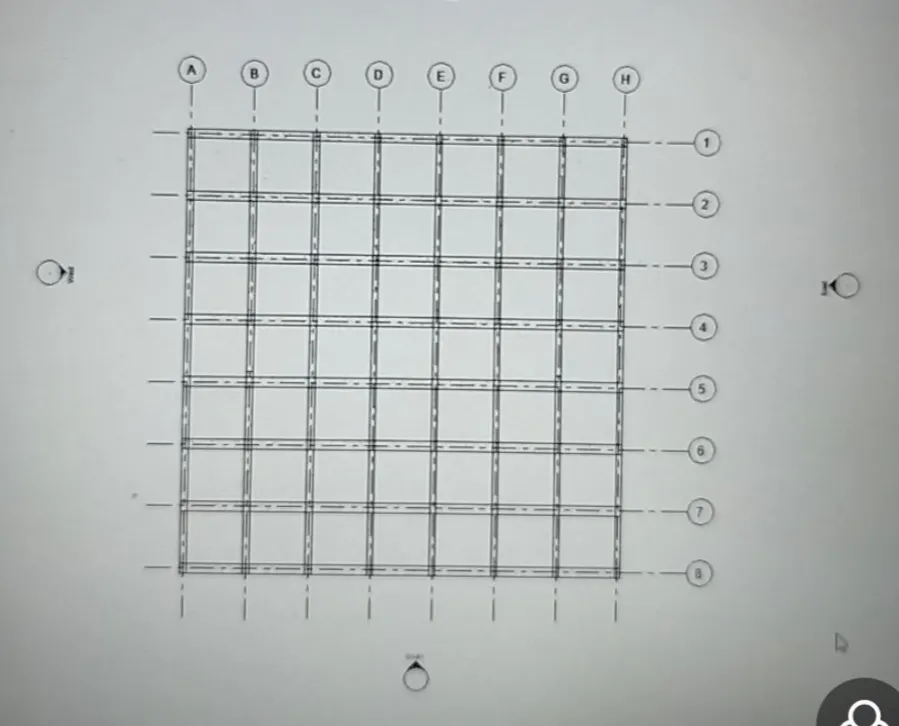
Open level 1 floor plan. Click on beam present in the structure tab. Draw boundary for the beam in between two columns and click on ok. Beam is formed. Similarly draw beams between all the columns in one floor. . Now copy all beams in level 1 floor to remaining levels.
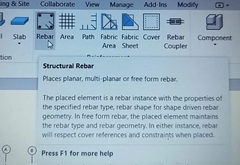
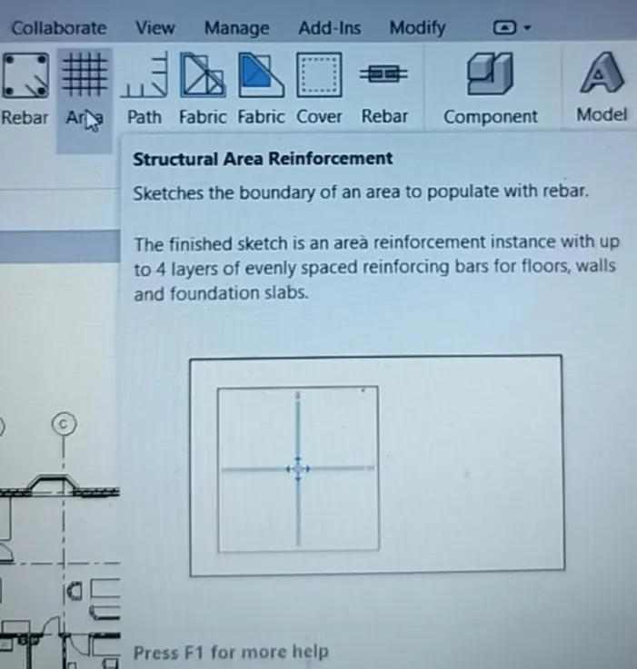
To add reinforcement to structural elements click on rebar / area present in structure tab.
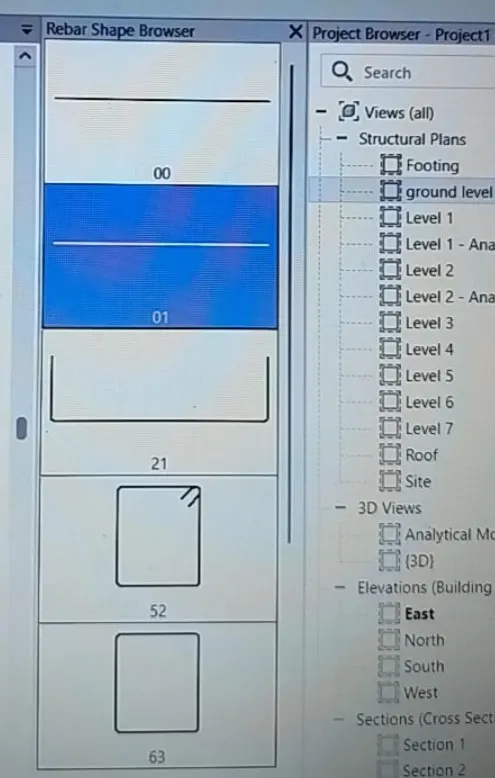
For reinforcement of footings, columns, beams we will select rebar which is present in the structure tab. A rebar shape browser will appear. Select required rebar shape and click on one footing. Now frame work reinforcement for a footing is formed. Similarly for a column and a beam also frame work is formed. Copy frame work of a footing and a column to other footings and columns. Similarly for beams also copy frame work which can be done by selecting a section view.
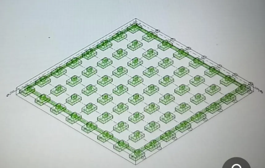
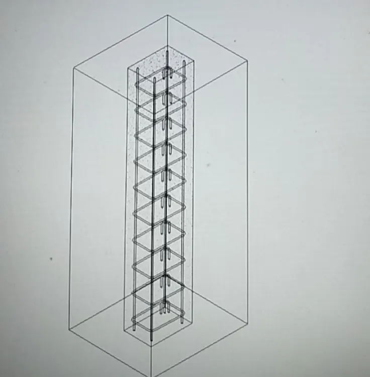
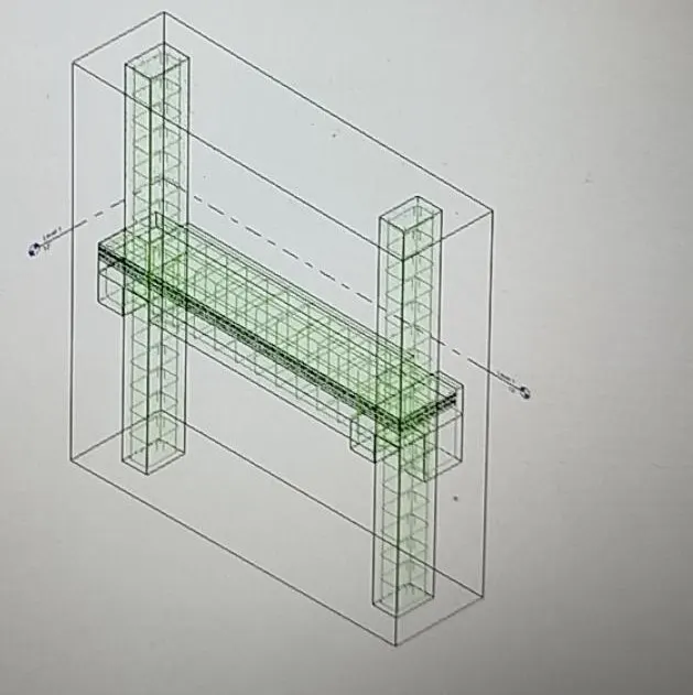
For structural walls , floors we will select area which is present in the structure tab. Select a wall. Now draw boundary and click on finish. Area reinforcement for a wall is formed. Similarly for all the walls we copy or select and area reinforcement frame work for walls can be seen. Similarly for floor also area reinforcement frame work can be seen. Copy it from one floor to other.
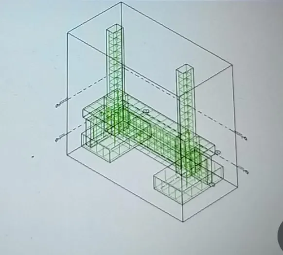
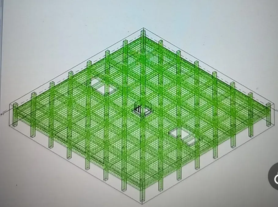
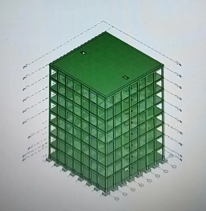
Structural model of 7 storey building with four units is finished.
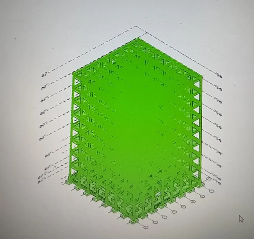
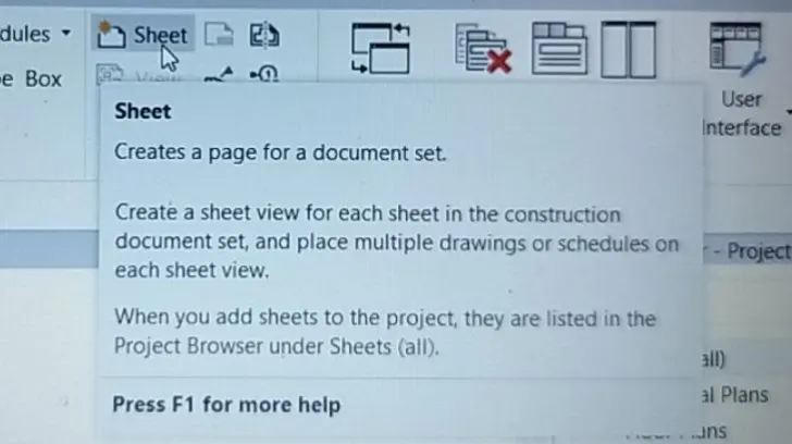
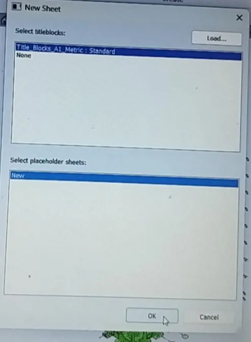
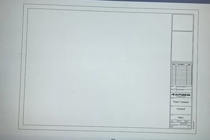
Now we can add floor plans, elevations, 3d views, sections of both architecture model and structure model to the sheets. Sheet is present in the view tab. By selecting new sheet and clicking on ok. A new sheet will be formed. By dragging all the floor plans/ elevations/3d views/ sections from project browser we can see all of them in sheets. We can take printout of the layouts of the plans .
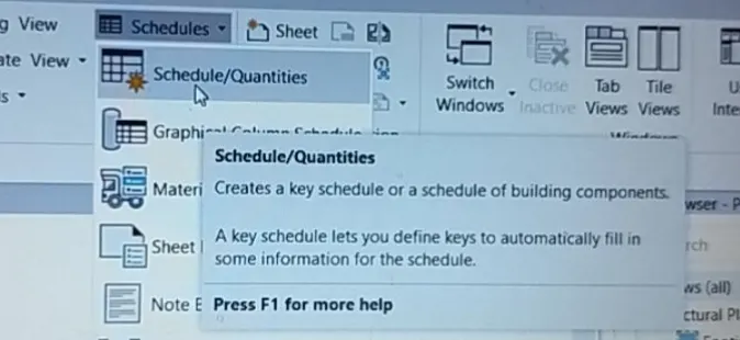
We can also prepare bill/ quantities schedule for different items like wall schedule, floor schedule, door schedule , etc. by clicking on schedules present in the view tab. We can prepare schedule for both architecture model and structure model.
Result : Architecture and structure model of 7 storey building with 4 units in each floor is finished.