Project 2
Aim: To run and simulate the full vehicle model and measure the current and hydrogen consumption and also to verify that desired velocity ~= Actual velocity
Blocks Used:
- Constant
- Drive Cycle Source
- Goto/ From
- Scope
- Sum
- Gain
- Switch
- Derivative
- Integrator
- Saturation
- Display
- Absolute
- Max/Min
- input/Output Ports
- Saturation Dynamic
- 1-D/2-D lookup Table
- Reciprocal
- Interval Test
- AND
- OR
- Greater than or Lesser than
- Square root
- Memory Block
- Multiply
- Interpreted MATLAB Fcn
- atan
Here i have designed a HEV Full Vehcile Model where it is fed by Battery and Fuel Cell assisted by an UC for peak power demands.
Model contains mainly three blocks, namely: Driver Block; Power Train; Vehcile Model
Now we will see all the subsystems that are designed in order to complete the vehcile with some realtime parameters.
Here the simulation is ran for 400 sec as the drive cycle is for 600sec.
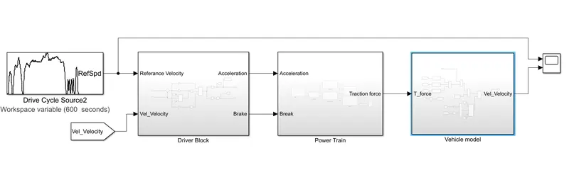
Inside Driver Block:
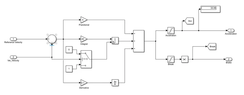
Inputs to this block are "Reference Velocity" which is fed by a drive cycle source and desired velocity came from vehicle model is fed back to the driver block to reduce the error[closed loop].
Both the inputs are fed to sum from which we convert the velocity into acceleration by integration and brake is considered as negative velocity but we can't give negative input so we have connected an absolute block in order to feed to power train block.
Saturation is used in order to regulate the value of input that is flowing through.
Inside PowerTrain:
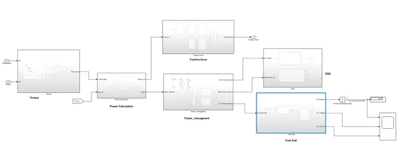
Here we have 6 subsystems inside it which consists of: Torque; Power Calculation; Power Management; Fuel Cell; Tractive Force; EMS(Energy Management System)
(a) Inside Torque:
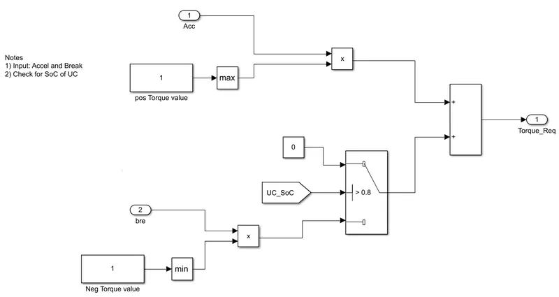
Torque is decided by the accelaration and brake demands that we recive from driver block.
Brake signal will be compared to UC_SOC because this is where regenrative braking is observed and SOC plays a vital role in order to decide the charging of UC.
We sum up the two values and decide the required torque and it is fed to Power calculated block.
Acceleration is multiplied with positive torque and brake is multiplied with negative torque.
(b) Inside Power Calculation:
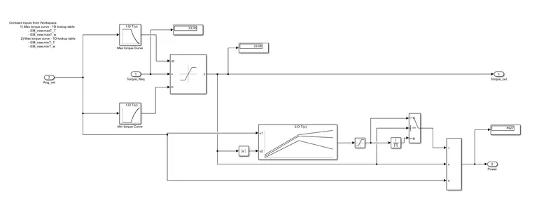
As the torque depends on angular velocity of the wheel, it will be fed to a dynamic saturation block through min and max 1-D lookup torque tables.
Torque required is given actual value "u" and both "up" and "lo" values are compared and then the output will be delivered.
As we know Power = speed * torque, we consider angular velocity as speed and it is being multiplied with torque which is further divided by 2-D lookup efficiency table.
Hence the final power and out torque are obtained from the Power block.
(c) Inside Power Management:
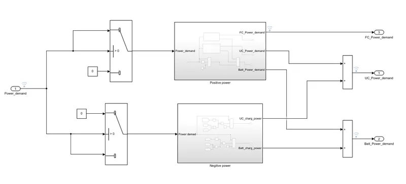
From the power demand we get from the vehicle it is decided whether it is a positive power or the negative power.
(c1) Inside Positive Power:
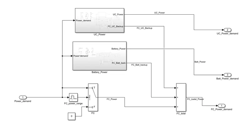
Here the positive power has two divisions because at peak power requirement(i.e., during high acceleration) UC will supply power to the vehicle.
Hence depend on the power demand it decides whether Battery or UC power is required otherwise the power demand is met by Fuel cell.
(c1(a) Inside Battery Power:
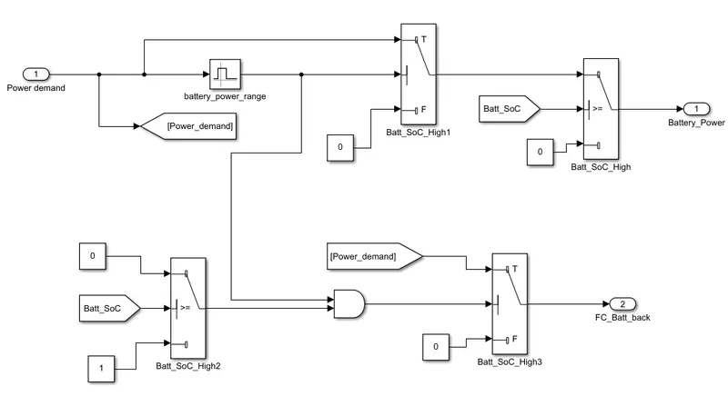
Here power demand comes in and it will further check with power range to check and battery SOC values to decide whether battery can supply power or not to the vehicle.
Here we have also other output going which is fed if Fuel cell failed to supply power.
(c1(b) Inside UC Power:
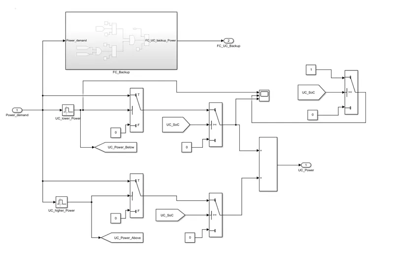
This above model is utilised during peak power demands like sudden acceleration or during uphilling also
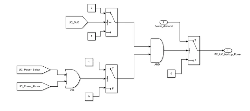
Above is the logic for FC Backup for an HEV
(c2) Inside Negative Power:
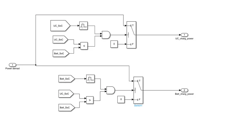
This is the block which is utilised during deceleration or whenever brake is applied[regenerative braking].
Here the power demand is compared with battery and UC SOC's respectively in order to decide what power source needs to be charged.
(d) Inside Tractive Force:
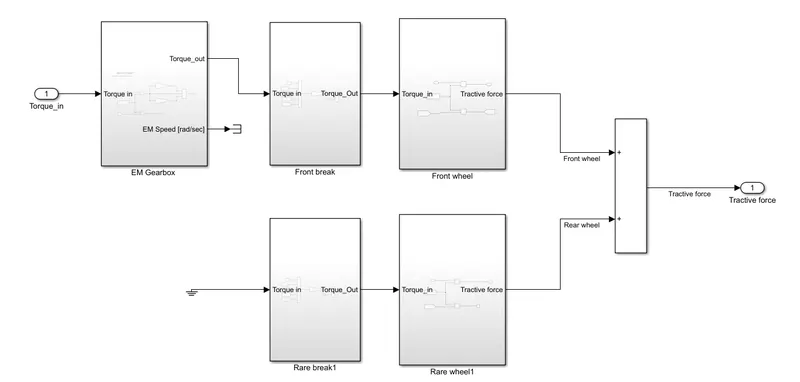
Now Torque is fed to gear box initially because of which the speed of the vehicle is decided.
(d1) Inside EM Gearbox:
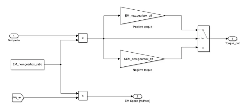
Here torque is multiplied with gearbox ratio which is fed to a switch, here predefined gearbox efficiencies are connected in the form of gain blocks[both negative and positive torque].
Now from the torque input it is decided whether a positive torque [during acceleration] or a negative torque[during deceleration] is decided, and this comes as torque output.
Front wheel angular velocity is multiplied with torque in order to calculate the speed.
(d2) Inside Front Brake:
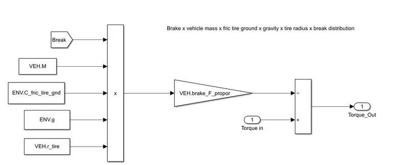
Brake block has so many varibales that are multiplied and fed to brake force proportional gain block.
Now the torque is subtracted from brake proportional to get the torque output.[brake_F_prop is "0" if no brake applied]
(d3) Inside Front Wheel:
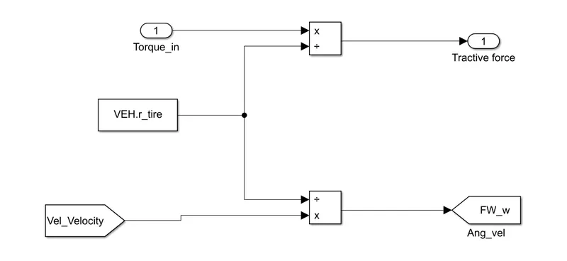
Now torque from brake block is divided with tire radius to get the required tractive force.
And velocity is divided with tore radius to get the front wheel angualar velocity.
(d4) Inside Rear Brake:
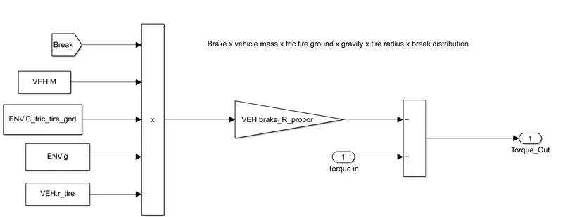
Brake block has so many varibales that are multiplied and fed to brake force proportional gain block.
Now the torque is subtracted from brake proportional to get the torque output.[brake_R_prop is "0" if no brake applied]
(d5) Inside Rare Wheel:
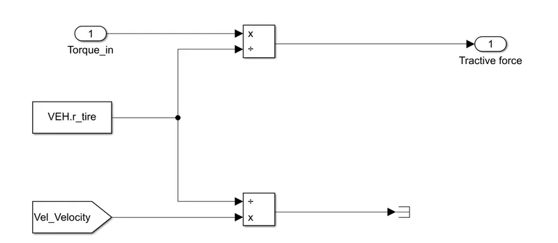
Now torque from brake block is divided with tire radius to get the required tractive force.
And velocity is divided with tore radius to get the front wheel angualar velocity.
(e)Inside ESS:
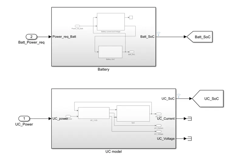
In the energy storage system we have two source of energy, namely Battery and UC model.
(e1) Inside Battery:
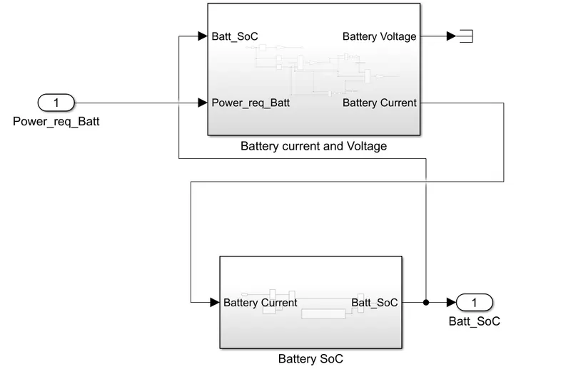
Here we need to calculate the Battery current and voltage in order to produce power for traction and also need to monitor the SOC of the battery.
(e1(a)) Inside Battery Current & Voltage:
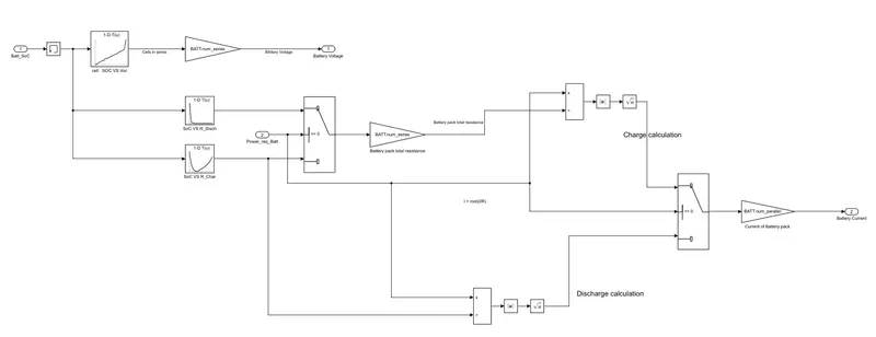
Battery current and voltage calculation is one of the complex calculation where we need many parameters that need to be considered.
First the Battery SOC is taken in order to produce power but at initial conditions the SOC would be zero which will not make the model to run, so a memory block is connected at the starting.
Here SOC is compared with open ckt voltage depens on which the voltage is produced [by considering series cells in the pack].
To calculate the charge SOC is further compared against resistance during and discharging which is then fed to switch to calculate the charge [ here also series cells are considered]
After calculating both charge and discharge current then the combined current is taken as output by multiplying with no.of parallel cells pack.
(e2) Inside SOC:
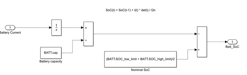
Above SOC calculation is done by following the above the equation mentioned over the blocks and design accordingly.
(e2) Inside UC:
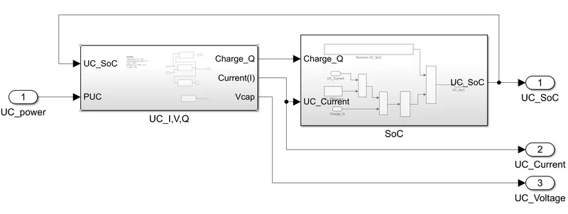
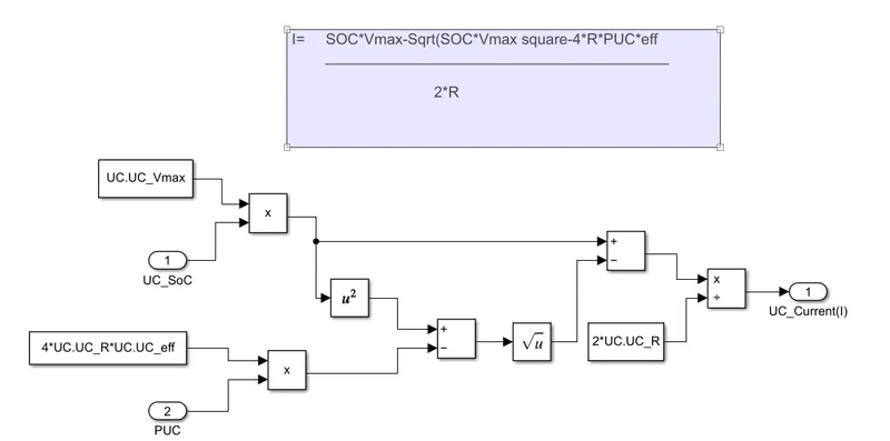
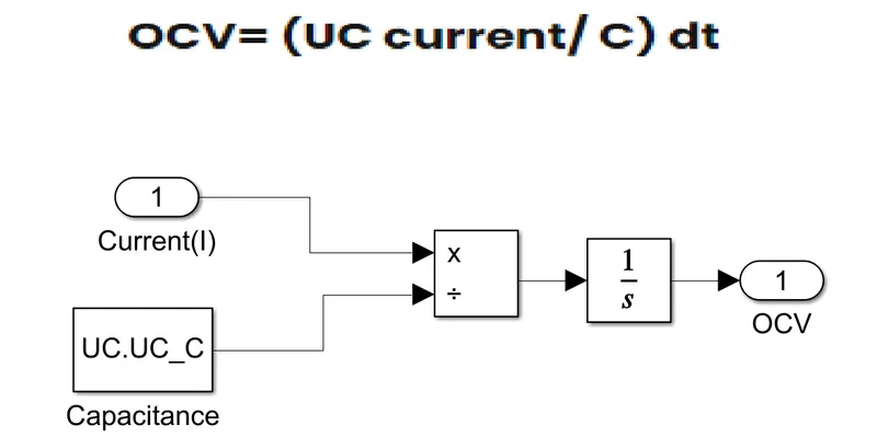
As followed in battery here also we calculate I,V, Q and SOC of UC.
(e2(a)) Inside UC_IVQ:
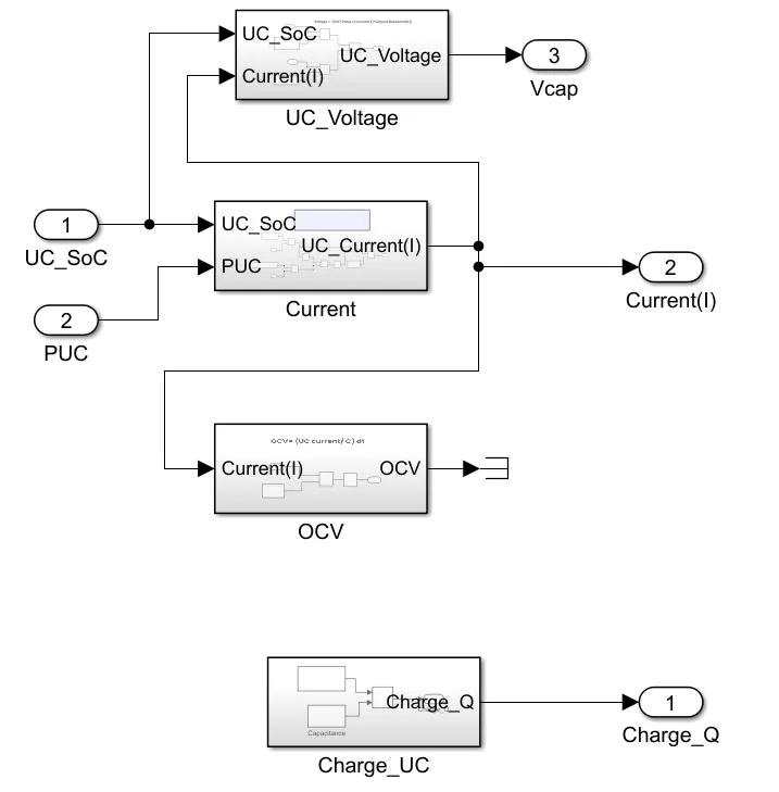
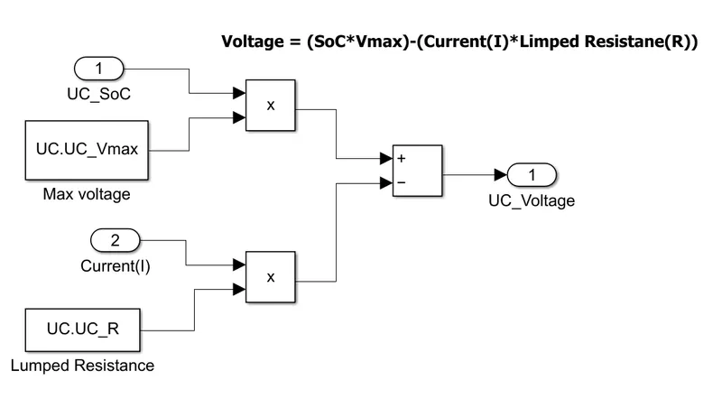
To calculate voltage:
To calculate UC Current:
To calculate Open Circuit Voltage:
To Calculate UC Charge:
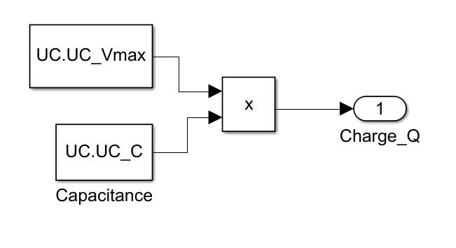
Charge of UC is calculated by the product of max voltage that can be delivered by UC to the capacitance value of UC
Note: Above entire UC calculation is performed by designing and connecting the necessary blocks by following the equations mentioned over the ckt.
(f) Inside Fuel Cell:
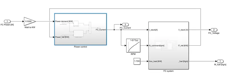
At the entry itself we are converting watts to kilo watts by connecting 1/1000 gain block.
Fuel cell current is compared with a graph where the rpm is compared against current [pre-defined].
Auxilary load denotes all the infotainment systems that are connected in vehicle.
(f1) Inside Power Control:
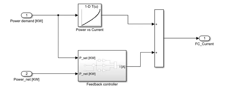
Power demand is fed to "P vs I" 1-D lookup table which is further added to the feedback controller output.This gives us the final current produced by fuel cell.
(f1(a)) Inside Feedback controller:
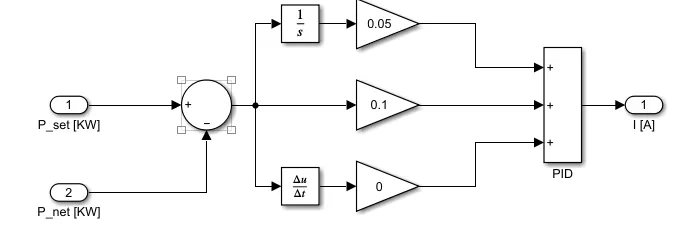
Here a PID controller is designed in order to minimise the errors while calculating the required current.
Now this controller current and current coming from power [which is compared to p vs i graph] came as total FC current.
Here gains of controllers can be varied depending upon the error corrections we want to implement into the system or by considering the trail and error process.
(f2) Inside FC system:
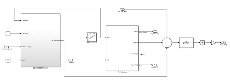
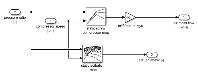
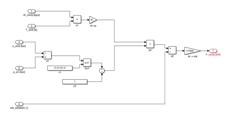
Fuel cell requires a compressor to release the fuel at a pressure in order to generate power.
Inside Compressor Model:
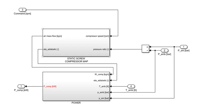
Inside Fuel Cell Stack:
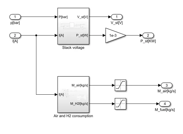
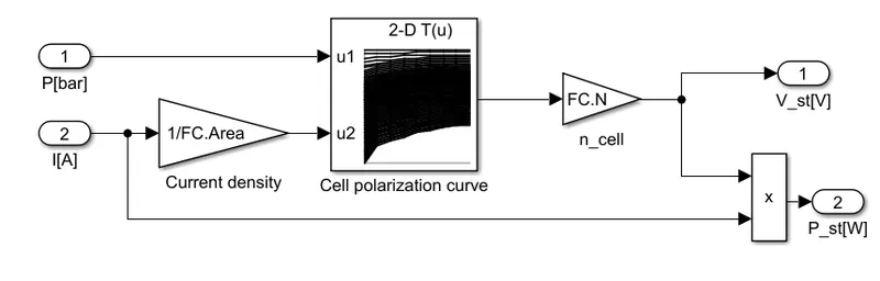
Stack Voltage
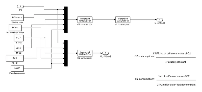
Air and H2 Consumed
From here we are going to calculate the Air and H2 consumption that are utilised by the vehcile during the simulation.
Note: Related equations are mentioned in snap to design the O2 and H2 consumption blocks.
Here we use integrator at H2 output port because we need consider the H2 that is being consumed for entire simulatinon time or the entire drive cycle.
Inside Vehicle Model:
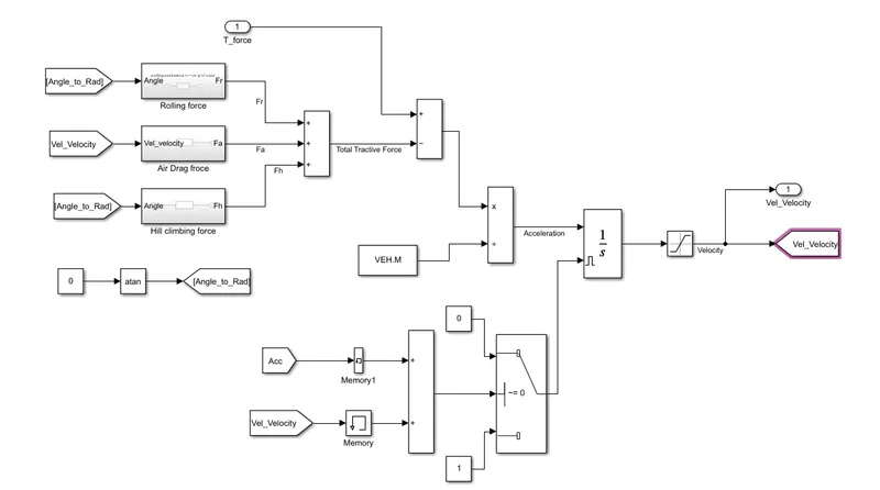
In this model we consider some real time forces that are experienced by a vehice that are: Air Drag force; Rolling Force; and Hill Climbing force
These all forces are designed by simply cosidering the necessary which are already known to us.
atan is used to convert the angle into radians because angle values cannot be computed by MATLAB.
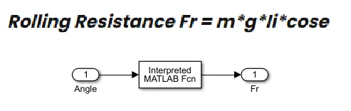
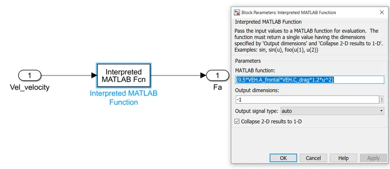
Air Drag Force
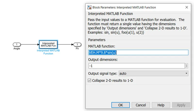
Hill Climbing Force
In order to get the actual tractive force utilised by the vehicle we are subtracting the external forces that need tractive force to overcome with the tractive force that is fed to.
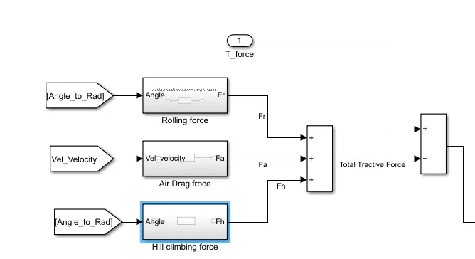
As we know F=m*a => a = F/m
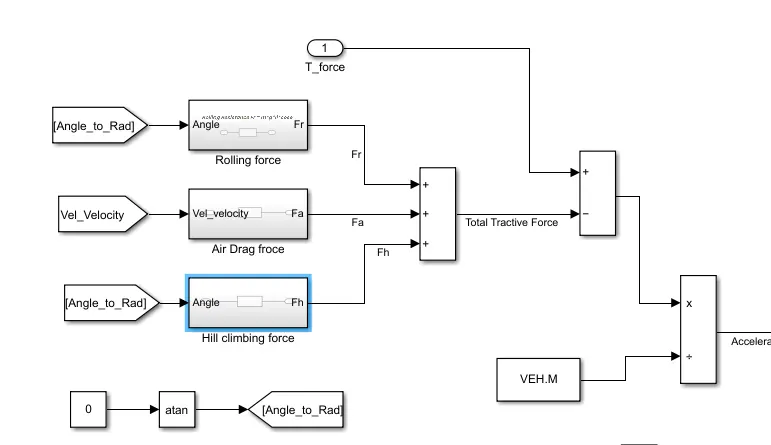
By this we obtained the acceleration of the vehcile.
Now to get the actual velocity we are integrating the acceleration obtained from above blocks.
The integration block is resetted by an external signal as the value in the integrator needs to be zero whenever the vehcile is at rest or when vehicle has stops during the whole travel time.
Now, finally we are comparing the Actual Velocity of the vehcile to the desired velocity that is fed by us externally.
Output:
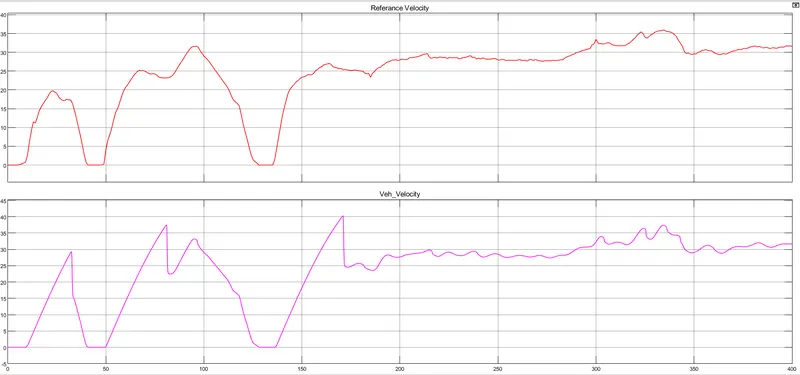
Here we got less difference between the average actual velocity and desired velocity, as the system ahs some real time parameters considered there will be a deviation from the actual to desired.
But more deviation in the output is not accepted as it denotes, that the vechicle has less efficiency.
Model file and all the parameters which are fed into this system are attached below.