Project 2
Simulink model:
System Level Configurations:
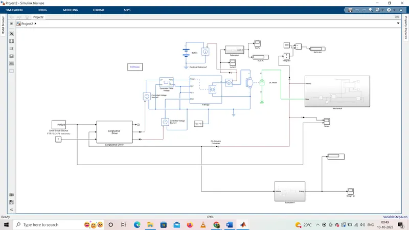
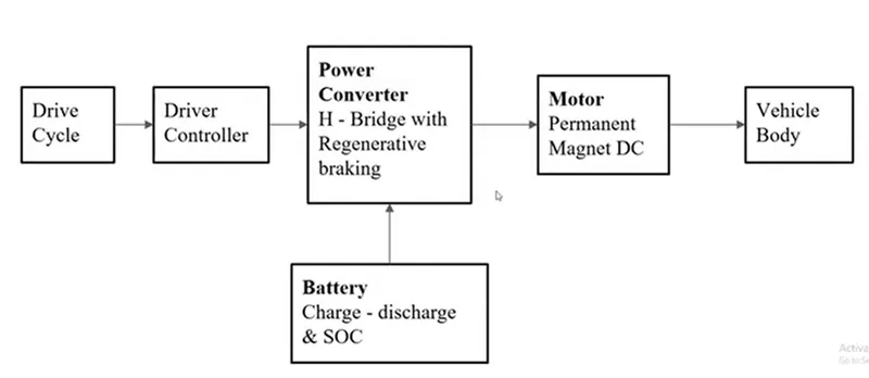
The Vehicle Model Mainly consists of :
1) Drive Cycle Source
2) Motor and Controller
3) Battery Pack and Power Converter
4) Vehicle Block
The battery pack is the powerhouse of Electric Vehicle model which provides/supplies power to motor and the other equipments necessary for efficient operation of the Electric Vehicle. The power converter converts the energy from battery to an optimum level as required by motor. The converter used is bi-directional which helps in taking back the regenrative energy to the battery thereby providing charging while deceleartion of vehicle. The vehicle body represents body of the vehicle with wheels which are connected to motor through a transmission system. The motor takes power from battery as per the load requirements with the help of controller which reviews load requirements and produces proportional control signals with the help of a feedback from vehicle so as to obtain a smooth and efficient operation of the vehicle. The drive cycle source is a reference driving pattern taken for simulation as per Drive cycle data.
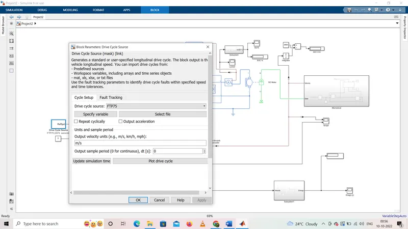
(1) Drive Cycle Source:
The Drive Cycle Source block generates a standard or user-specified longitudinal drive cycle. The block output is the specified vehicle longitudinal speed, which you can use to:
- Predict the engine torque and fuel consumption that a vehicle requires to achieve desired speed and acceleration for a given gear shift reference.
- Produce realistic velocity and shift references for closed loop acceleration and braking commands for vehicle control and plant models.
- Study, tune, and optimize vehicle control, system performance, and system robustness over multiple drive cycles.
- We can choose different drive cycles for our simulation such as WTO, US06, FTP75 by opening the drive cycle source block.
2] Driver Controller:
The drive cycle input is given to VelRef port, the feedback Vfdk is gained from vehicle body which will acts as the feedback signal connected to VelFdbk port. The AccelCmd & DecelCmd are two output signals given for accelerating and braking to the motor controller respectively. The info port is connected with the terminator block as we are not using any bus signals for this model. For a grade port a constant block is attached as road grade angle considered is 0 in our case, i.e our vehicle is running at a straight road.
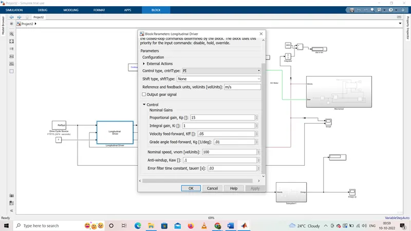
Input Ports:
- VelRef - port associated with input reference velocity of the vehicle (m/s)
- VelFdbk - port associated with velocity feedback from the vehicle body which helps in smooth control of system.
- Grade - port associated with gradeability of vehicle.
Ouput Ports:
- Info - port associated with a bus signal for deceleration, acceleartion, error in velocity etc
- AccelCmd - port which is associated with acceleration command with reference to input signal.
- DecelCmd - port which is associated with deceleration commads with reference to input drive signal.
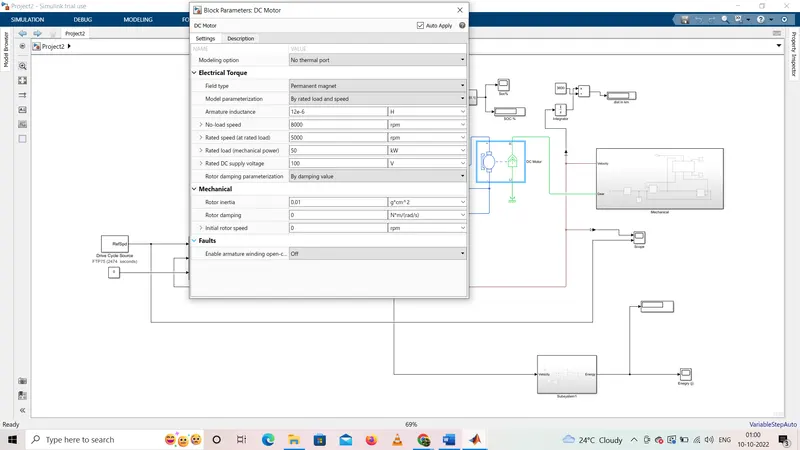
The below block represents electrical and torque characteristics of a DC motor. It is assumes that no electromagnetic energy is lost, and so the back-emf and torque constants have same numerical value when it is in SI units. The Motor parameters can either be specified directly, or derived from no-load speed and stall torque. If there is no information is available on armature inductance, this parameter can be set to quite small non-zero value.
When a positive current flows from the electrical + to - ports, a positive torque acts from mechanical C to R ports. Motor torque direction can be changed by altering the sign of the back-emf or torque constants.
(1) Controlled Voltage Source:
The Controlled Voltage Source block represents an ideal voltage source that is powerful enough to maintain the specified voltage at its output regardless of the current flowing through the source.
The output voltage is V = Vs, where Vs is the numerical value presented at the physical signal port.
The block has one physical signal input port and two electrical conserving ports associated with its electrical terminals.
The controlled voltage source block don't have it's own block parameters. It receives input signal from the longitudinal driver block and the output is given to H-bridge block.
(2) Contolled PWM Voltage:
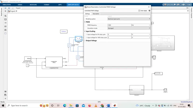
The block creates a Pulse-Width Modulated (PWM) voltage across the REF and REF ports. When the pulse is low the output voltage is zero and when the pulse is high, the output voltage is equal to the Output voltage amplitude parameter. Duty cycle is set by input value.
The Simulation mode can be set to Averaged or PWM. In the PWM mode, the output is a PWM signal. In Averaged mode, the output is a constant with value equal to averaged PWM signal.
(3) H-Bridge:
The H-Bridge block represents an H-bridge motor driver. The block has the following two Simulation mode options:
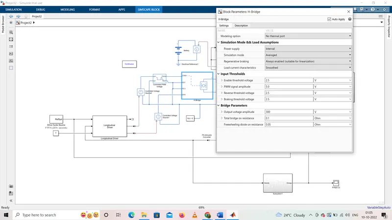
- PWM — The H-Bridge block output is a controlled voltage that depends on the input signal at the PWM port. If the input signal has a value greater than the Enable threshold voltage parameter value, the H-Bridge block output is on and has a value equal to the value of the Output voltage amplitude parameter. If it has a value less than the Enable threshold voltage parameter value, the block maintains the load circuit using one of the following three Freewheeling mode options:
- Via one semiconductor switch and one freewheeling diode
- Via two freewheeling diodes
- Via two semiconductor switches and one freewheeling diode
The first and third options are sometimes referred to as synchronous operation.
The signal at the REV port determines the polarity of the output. If the value of the signal at the REV port is less than the value of the Reverse threshold voltage parameter, the output has positive polarity; otherwise, it has negative polarity.
- Averaged — This mode has two Load current characteristics options:
1) Smoothed
2) Unsmoothed or discontinuous
] Vehicle Block:
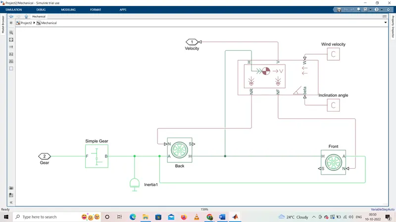
The vehicle block is shown below which consists of vehicle body, gear and transmission system.
For this subsystem a set of 4 tire block are used - 2 for the front axle and 2 for the rear axle and the required connections are made with vehicle body block. The normal force signals from the vehicle body block are sent to the normal force input ports of the tires.
A ports of the tire is the mechanical rotational conserving port which receives mechanical rotational input from the gearbox which receives its input from the DC motor.
H port of the tire is mechanical translational conserving port for wheel hub and is connected to H port of the vehicle body through which the thrust developed by tire is applied to the vehicle.
For our modelling we are not considering any slip, so an terminator block is connected to all the slip port of each tire. Also, grade angle and wind velocity are not considered PS contant block for termination are used.
The input is received from the DC motor to the simple gear block which is then transmitted to the wheel for the propulsion.
(1) Vehicle Body:
The Vehicle Body block represents a two-axle vehicle body in longitudinal motion. The vehicle can have the same or a different number of wheels on each axle. For example, two wheels on the front axle and one wheel on the rear axle. The vehicle wheels are assumed identical in size. The vehicle can also have a center of gravity (CG) that is at or below the plane of travel.
The block accounts for body mass, aerodynamic drag, road incline, and weight distribution between axles due to acceleration and road profile. Optionally include pitch and suspension dynamics. The vehicle does not move vertically relative to the ground.
The block has an option to include an externally-defined mass and an externally-defined inertia. The mass, inertia, and center of gravity of the vehicle body can vary over the course of simulation in response to system changes.
(2) Tire:
The Tire (Magic Formula) block models a tire with longitudinal behavior given by the Magic Formula, an empirical equation based on four fitting coefficients. The block can model tire dynamics under constant or variable pavement conditions.
The longitudinal direction of the tire is the same as its direction of motion as it rolls on pavement. This block is a structural component based on the Tire-Road Interaction (Magic Formula) block.
Ports
S - output port that reports the tire slip
A - It is the mechanical rotational conserving port for the wheel axle
N - input port that applies the normal force acting on the tire
H - It is the mechanical translational conserving port for the wheel hub
(3) Gear:
The Simple Gear block represents a gearbox that constrains the connected driveline axes of the base gear, B, and the follower gear, F, to corotate with a fixed ratio that you specify. You choose whether the follower axis rotates in the same or opposite direction as the base axis. If they rotate in the same direction, the angular velocity of the follower, ωF, and the angular velocity of the base, ωB, have the same sign. If they rotate in opposite directions, ωF and ωB have opposite signs.
Model Output
Scope result for velocity vs drivecycle output
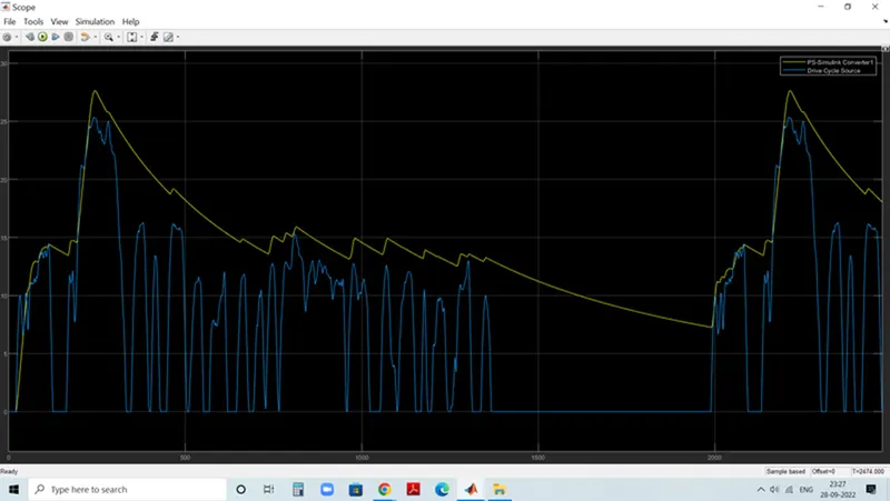
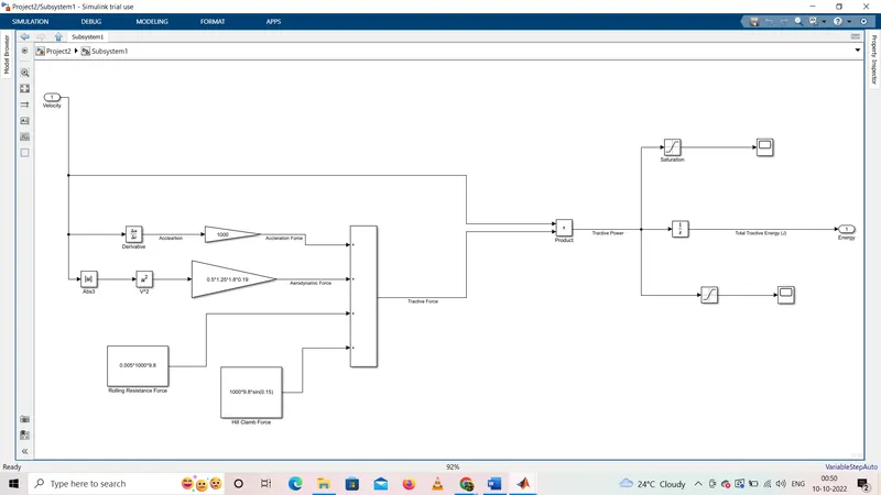
Energy output in scope as per below

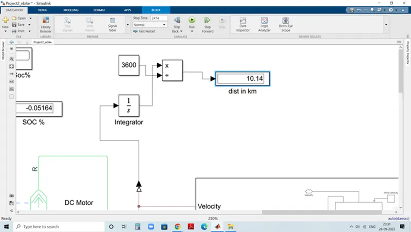
for given input drive cycle vehicle travelled 10.14 as shown below result in model
Dist is calculated by integrating a velocity
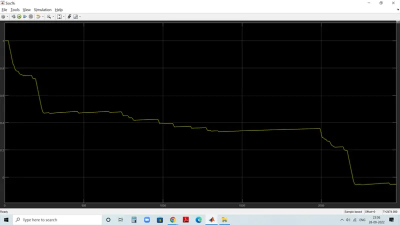
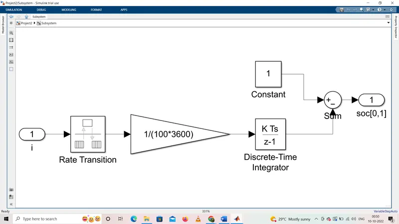
we get a battery State of charge graph as below in which we can see because regenerative breaking some times soc is increases.