Project 1
The fan speed is varied according to the input voltage using PWM technique.Fan type equation has been used instead of connecting it on the shaft of the dc motor physically.
DC Motor:
It is a rotatory elctrical motor that converts DC elctrical energy to mechanical energy.They mostly rely on forces produced by magnetic fields.DC motor consists of two parts ,the stationary part called the STATOR,and the inner part which rotates called ROTOR.DC motors classified into different types which work on the same principle and is construction is done by establishing a magnetic field with elctromagnet or permanent magnet. A PMDC is a kind of motor used here to form the magnetic field for the operation of DC motor.PERMANENT MAGNET DC MOTOR incudes armature core,commuttator and armature windings.
Working of PMDC motor:
Here,the permanent magnetic field is can be generated with the Permanent magnets that communicate by the perpendicular field which is energised by the flow of currents within the rotor windings by which TORQUE is created.When the rotor rotates in response to the created torque, then the position among the stator as well as rotor fields can be reduced, and the torque would be reversed in a 90-degree rotation. To maintain the torque performing on the rotor, PMDC motors include a commutator, set to the rotor shaft.
The rotational speed of a DC motor(N) is proportional to the back EMF (Vb)of the motor divided by the magnetic flux times an Electromechanical constatnt depending on the nature of the ramture windings (Ke) giving us the eq of
N ∝V/Keϕ
PWM(Pulse-width modulation) :
It is a method of rducing the average power delivered by an Electrical signal ,be chopping it effecticely inti discrete parts.The average value of voltage and current fed to the load is controlled by turning the swivh b/t the supply and load ON and OFF at fast rate.The longer theswitch is on compared to the off periods,the higher the total power supplied to the load. It is one of the primary methodsalong with the MPPT, of reducing the output of solar panels to that which can utilized by a battery.PWM is suitable particullarly for running inertial loads such as motors,which are not as easily affected by the discrete switching,because there inertia cause tehm to react slowly.

fig: PWM modulation
In this ,design by changing the timing of this pulses,the speed of the motor can be controlled.A stepwise change in speed is given and full load speed is observed.
In this model, all input ports of the H-Bridge block except the PWM port are connected to ground. As a result, the H-Bridge block behaves as follows:
- When the motor is on, the H-Bridge block connects the motor terminals to the power supply.
- When the motor is off, the H-Bridge block acts as a freewheeling diode to maintain the motor current.
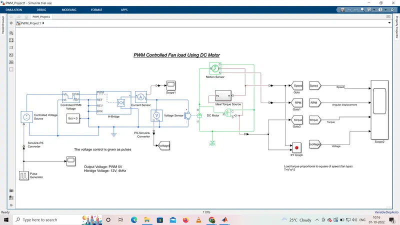
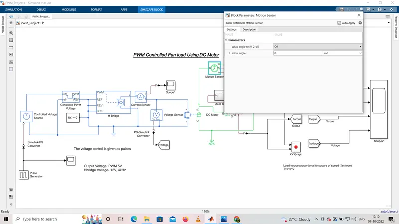
Simulink design of PWM controlled fan load using DC motor
MODEL explanation :
Torque exerted by fan is represented byT
T=K.w^2
By varyng the elctrical parameters of motor,we can control the load speed.
Fan load is represented by an equation (with in a subsystem) using gain block with (8.8e-8) and product block (w^2).
The o/p of the system is fed by Aerodynamic bolck which is Ideal Torque source which apply torque on the shaft of DC motor.
MOTION SENSOR is used for the speed analysis which is guven to te sub system w and torque is gucen to the aerodynamic block
PULSE generator is given as input to the controlled voltage source,which is connected to the PWM controlled volatage and H-bridge to pwm voltage .
Parameters values for the given blocks are givenas follws.
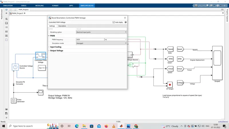
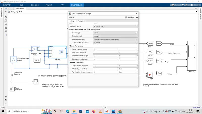
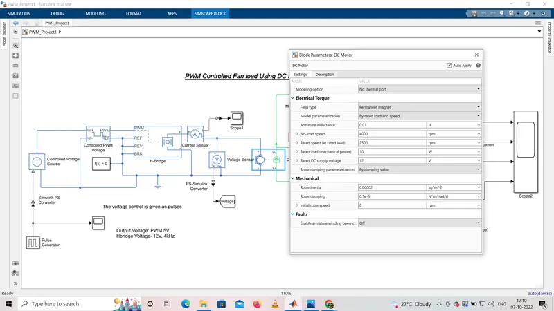
The out put results of xy graph, scope,scope1,scope2 are given below.
In the output,the voltage change with respwct to the pulse duty ratio ,speed increases and in square portion torque increses.increase in angular displacement is seen as step waveform.
CONCLUSION:
A PWM controlled DC motor using an H bridge circuit was modelled in Simulink and results were analyzed where Speed,Torque,angular displacement of a fan waveforms match with desired response and Load Torque charecteristics of a fan is obtained.