Project 3
A BUCKCONVERTER (step-down converter)is a DC-DC power converter,which steps down the voltage from i/p to its o/p.
It is a class of Switched Mode Power Supply typically comaining 2 semiconductors 1.DIODE 2. TRANSISTOR although modern buck converters frequently replace the diode with a second transistor used for synchrous rectification and and atleast one energy storage element or ,the two (capacitor,inductor) in combination.
To reduce the ripples in voltage ,filters made of capacitors are normally added to such a converters o/p and i/p .
Switching converters provide greater efficiency as DC-DC converters than Linear regulators that are simole and lowers the voltages by dissipating power as heat.
The efficiency of BUCk converters can be of 90%.
Operating Principle of BUCK converter:
The figure given below shows the circuit representation of Buck Converter: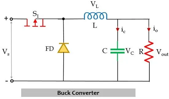
In figure, it is shown that along with the power electronics solid-state device which acts as a switch for the circuit, there is another switch in the circuit which is a freewheeling diode. The combination of these two switches forms a connection with a low-pass LC filter in order to reduce current or voltage ripples. This helps in generating regulated dc output. A pure resistor is connected across this whole arrangement that acts as a load of the circuit.
The whole operation of the circuit takes place in two modes. The first mode is the one when the power MOSFET i.e., switch S1 is closed.
In this mode of operation, switch S1 is in closed condition thus allows the flow of current to take place through it.
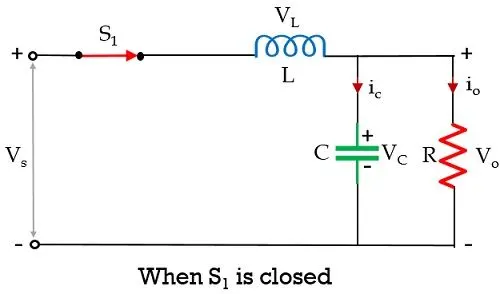
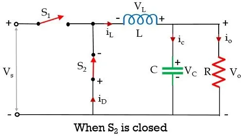
Initially when a fixed dc voltage is applied across the input terminal of the circuit then in the closed condition of switch S1 current flows in the circuit in the manner shown above. Due to this flowing current, the inductor in the path stores energy in the form of a magnetic field. Also, there is a capacitor in the circuit and current flows through it also, therefore, it will store the charge and the voltage across it will appear across the load.
However, due to Lenz’s law, the energy stored within the inductor will oppose the cause which has produced it and so an induced current will get generated and the polarity across the inductor will get reversed.
Here the total time period is a combination of Ton and Toff time.
T = Ton + Toff
The duty cycle is written as:

To design a Buck converter for auxillary load in EV , the given data are
- Input voltage is 48V, Output voltage is 12 V
- Load current is 10A
- To Calculate Duty ratio and Load(use Resistor as Load)
- Calculate L,C
If f=40Khz
Ripple factor is assume to be 0.5%
Vo =R*iL
-->%Duty ratio (D)= (Vo/Vin)*100
=12/48=0.25
=0.25*100=25%
-->Min inductance =[(1-D)*R]/(2*f)
= [(1.025)*1.2]/(2*40000)
=11.25micro henry
-->Max Inductance =1.25*Lmin
=1.25*11.25micro henry
-->Capacitance =(1-D)/(8*L*r*f^2)
(1-0.25)/(8*14*10^-6*r*40000^2)
=837 micro farad.
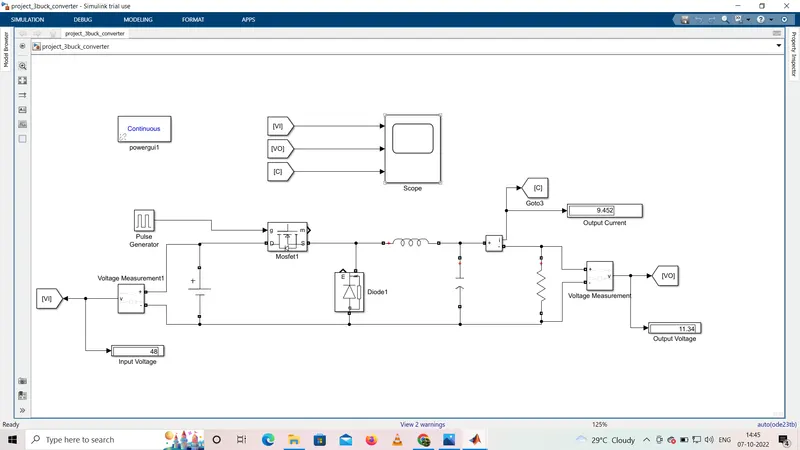
Simulink block diagram of Buck COnverter used in Ev :
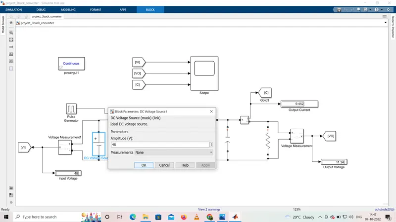
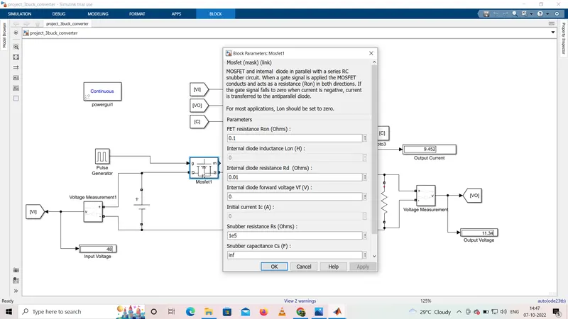
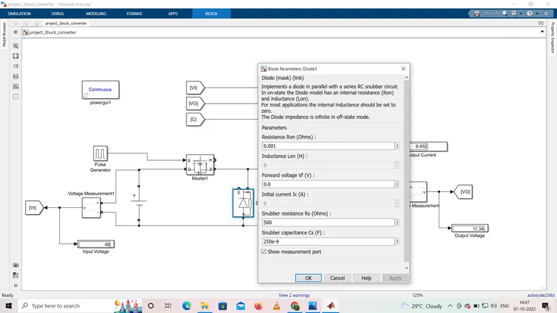
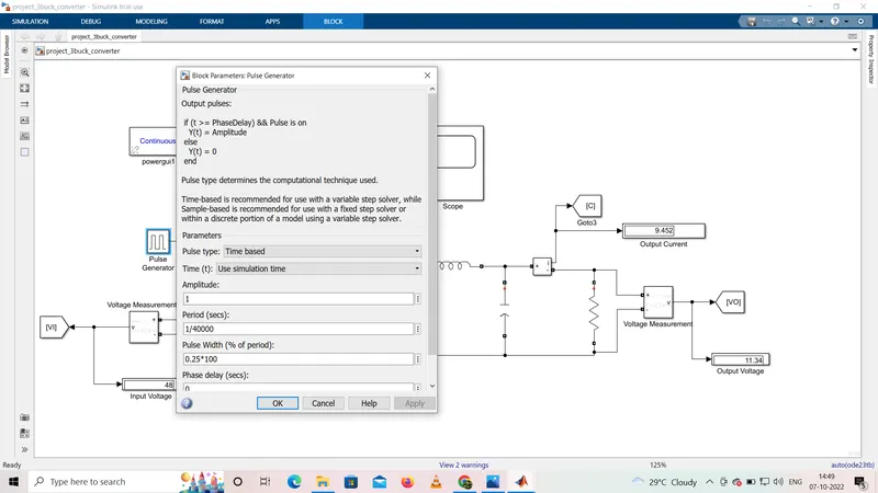
Switching Device:
Mosfet and internal diode are in parallel with the series RC circuit.when a gate signal is applied ,the mosfet conducts and acts as a resistance in both directn.If the gate siganl falls to zero,when there is negative current,the current is transferred to the anti parallel diode.
- Pulse generator is used as control unit from which i/p is given through the duty cycle.
OUTPUT:
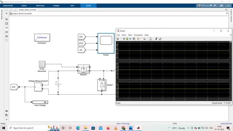
The first wave form is the input voltage of 48v,
The second is the o/p voltage which is the required voltage of 11.34v near to 12v ,load current is 9.45A .There is variation in o/ps due battery chemistry and lossess.