Project 2
AIM:-
Design an MPPT controller with Boost to meet the following specifications and obtain the simulation results.
PV output voltage/ Input voltage of converter=250-350V
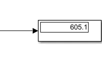
Output voltage= 600V
Rated PV power =100kW
Switching frequency=5kHz
Current ripple=5%
Voltage ripple=1%
Repeat the above using a two-stage Interleaved Boost converter and compare MATLAB results.
MODEL:-
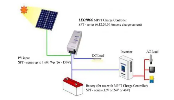
The major principle of MPPT is to extract the maximum available power from PV module by making them operate at the most efficient voltage (maximum power point). That is to say:
MPPT checks output of PV module, compares it to battery voltage then fixes what is the best power that PV module can produce to charge the battery and converts it to the best voltage to get maximum current into battery. It can also supply power to a DC load, which is connected directly to the battery.
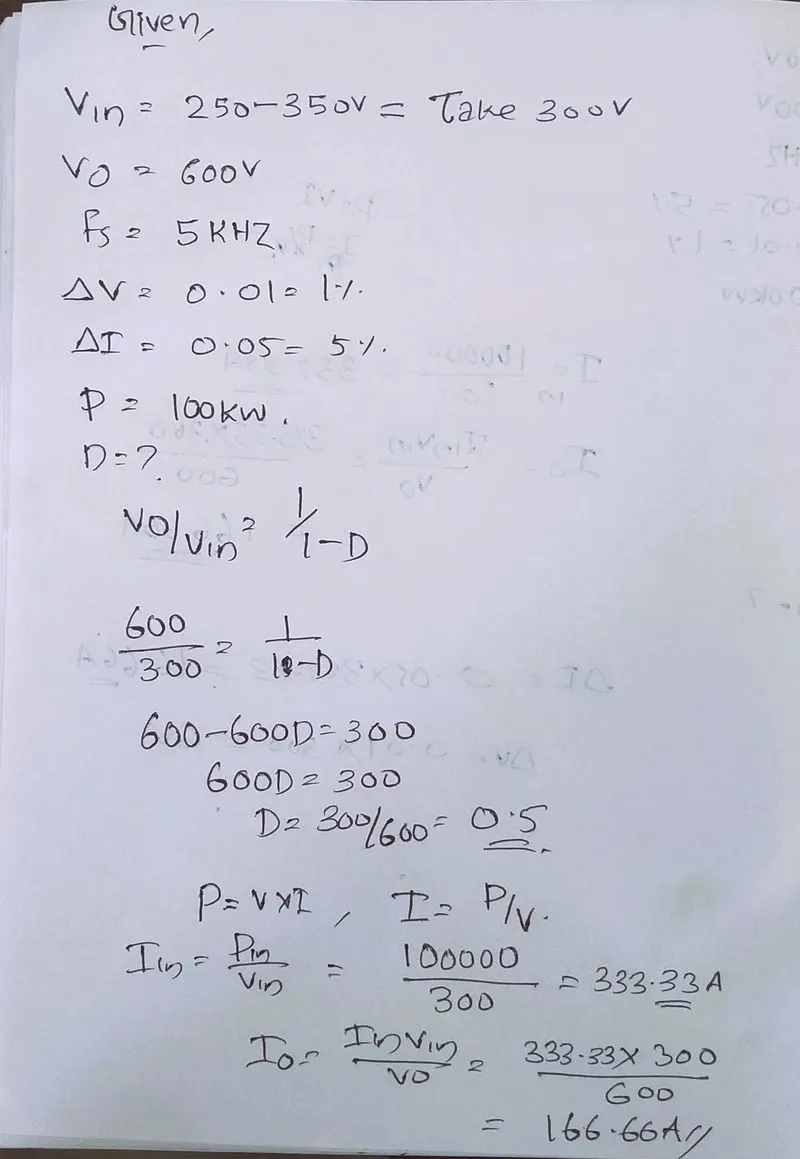
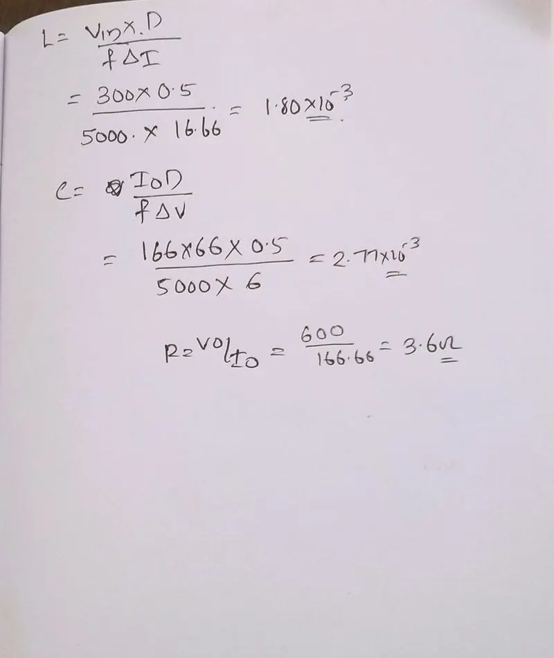
Calculations:-
Simulink model:-
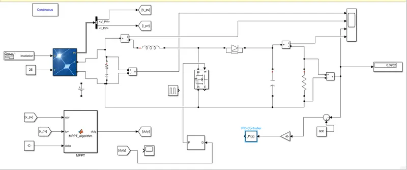
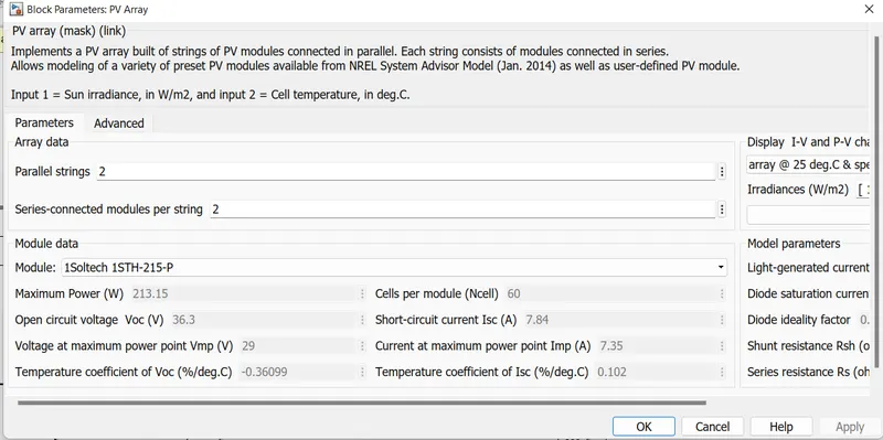
PV array:-
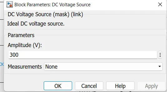
DC source:-
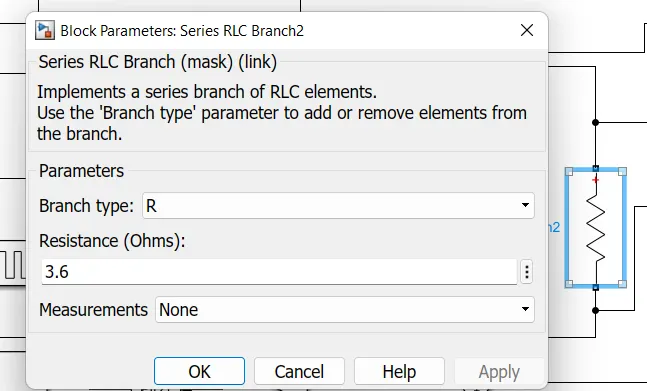
Resistor:-
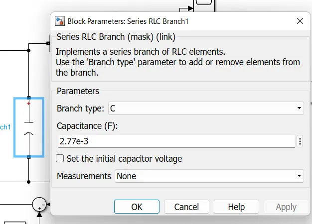
Capacitor:-
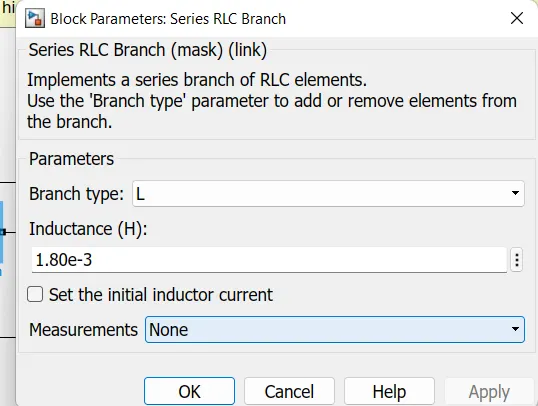
Inductor;-
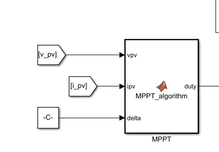
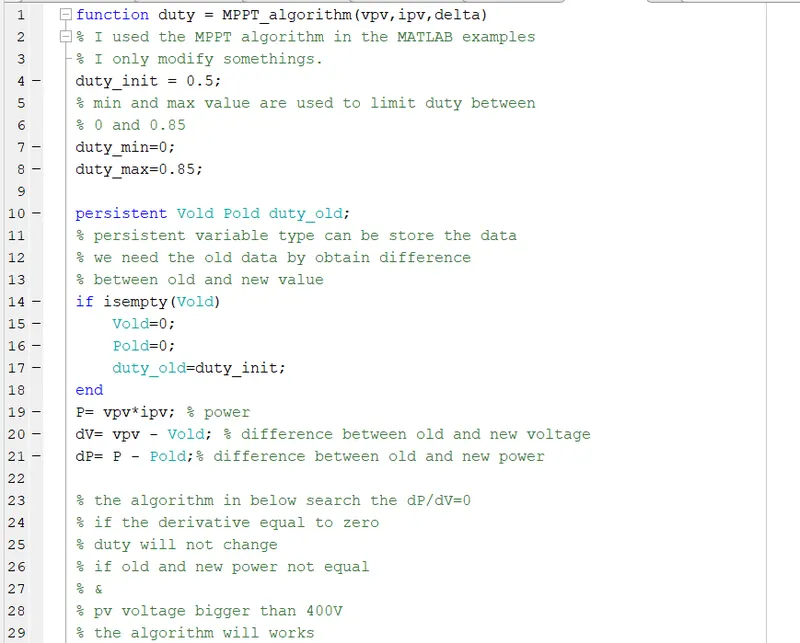
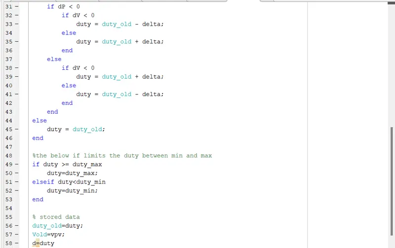
MPPT:-
RESULTS:-
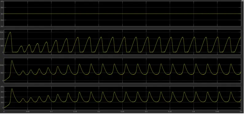
Boost converter result
without controller
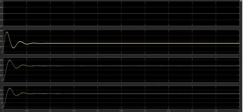
with controller
output
2.
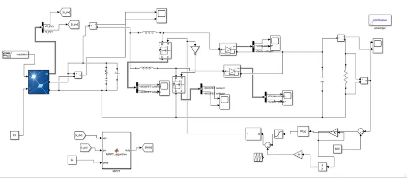
using a two-stage Interleaved Boost converter
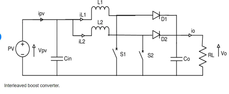
Simulink model:-
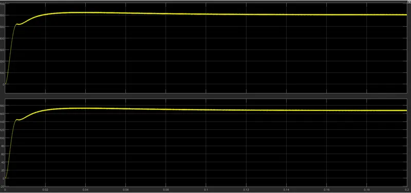
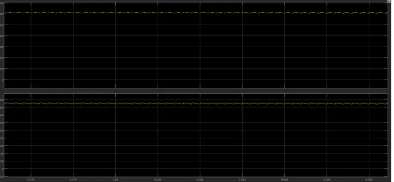
Result/interleaved boost converter
* interleaved-boost converter, magnetically coupled to a voltage-doubler circuit, which provides a voltage gain far higher than that of the conventional boost topology.
* this converter has low-voltage stress across the switches, natural-voltage balancing between output capacitors, low-input current ripple, and magnetic components operating with the double of switching frequency.
* this converter suitable to applications where a large voltage step-up is demanded, such as grid-connected systems based on battery storage, renewable energies, and uninterruptible power system applications.
compare MATLAB results.
interleaved boost converter has low-input current ripple compare with boost converter so interleaved boost converter is much better.