Project 2
Certainly the bridge will be constructed in sea shore where it has to face water current force, wave force and Barge impact load. Also the bridge alignment is in curve, so centrifugal force is inevitable. The project region is snowy and tempreture difference is greater than 20.
Aim is to design a safe bridge considering different loads, such as water current force, centrifugal force, wave force,snow loads, tempreture loads and barge impact load.
1. Water current force:
Highest flood Level = 104m (Foundation level assumed 100m)
River Bed Level = 100m
The height of Pier subjected to water current H = 4m
The mean velocity of the river V is 2.5m/s
Maximum velocity V = square root 2 X V = 3.54m/s
Pier is square (1.2X1.2), so K will be 1.5
Water current loads = 52K v square = 52 X 1.5 X 3.54 X 3.54 = 977.465kN/m square
For 1.2m wide pier = 1.2 X 977.465kN/m squre = 1172.96kN/m.
2. Centrifugal force:
Design speed V = 50km/hour
Radius of curvature R = 2m
Live load W = 70R = 70kN Width of vehicle (axle to axle) 2.06m and length wise 4.57m
Centrifugal force C = W V square / 127 R = 70 X 50 X 50 / 127 X 2 = 688.98kN
3. Wave Force:
 Zh = n max - centroid of I girder.
n max = 3m
centroid of I girder = (Depth of I girder + Thickness of deck slab)/2 = (1.6+1.5)/2 = 1.55m
Zh = 3-1.55 = 1.45m
Zv = n max - Elevation of bottom deck = 3 - 0.8 = 2.20m
Verticle load Fv = r X Zv X Av
r = 5
Av = Deck Width X (Deck slab thickness with girder and parapet/2 ) = 10.5 X 3.1/2 = 16.275
Verticle load Fv = 5 X 2.20 X 16.275 = 179.025kN
Horizontal Load Fh = r X Zh X Ah
Ah = 3.1 X 40 = 124
Horizontal Load Fh = 5 X 1.45 X 124 = 899.00kN
Max verticle load = Fv max = Cva X Fv
Cva = 3
Max verticle load = 3 X 179.025 = 537.08kN
Max horizontal load = Fh max= ( 1 + Cr (N-1)) Cva X Fh
Cr = coefficient = 0.4
N = Number ofGirder = 4
Max horizontal load = Fh max= (1 + 0.4 (4-1)) 3 X 899.00 = 5933.40kN
4. Snow Load:
Setteled snow having density = 3kN/m cube
Bridge deck is < 30 degree
The depth acumulation of snow is 1250mm = 1.25m
Bridge Length is 40m
Snow Load So = 3kN/m3 X 1.25m X 40m = 150kN/m
Shape co efficient from IS 875 part - 4 for shape b < 30 degree m = 0.8
Design snow load S = So X m = 150 X 0.8 = 120.00kN/m
5. Tempreture Load:
Suppose the bridge project is near by delhi where max tempreture is 47.8 degree and lowest is - 0.4 degree. The grade of concrete is M-40.
Maximum tempreture in the location = 47.8 degree
Minimum tempreture in the location = - 0.4 degree
Effective tempreture difference Delta T = (47.8-(-0.4))/2+10 = 34.10 degree
Coefficient of thermal expansion Alpha = 11.27 X 10 to the power -6
Modulous of elasticity of material E = 5000 X square root of 40
Stress due to tempreture= alpha X Delta T X E = 12.15kN/m2
Maximum permissible stress=(2/3) X 0.7 X square root of fck = 2/3 X 0.7 X square root of 40
=2.95kN/m2 say 3kN/m2 Hence the stresses are restricted to 3 kN/m2
Maximum Tempreture = 47.8 degree
Minimum Tempreture = - 0.4 degree
Positive tempreture difference
Tempreture at Top = 47.8 degree
Tempreture at bottom = 2.1/17.8 X 47.8 = 5.64degree
Temperature difference from top to bottom = 47.8-5.64=42.16
Temperature change for Axial Bongation = 30
6. Barge Impact load
KE = 500 X CH X W X V square
Where W - Barge displacement tonnage(T) = 25000 DWT
CH - Hydrodynamic coefficient = 1.25 assumed
V - Barge impact speed (m/s) = 50km/hour = 13.889m/s
KE = 500 X 1.25 X 13.889 X 13.889 = 3014130016N-m
Barge damage depth, aB = aB= 3100 X ([1+1.3 X 10to the power -7 KE]to the power 0.5 -1) = 58342.352mm
For aB > 100mm, PB =6.0 * 10 to the power 6 + 1600 * (aB), in N = 99347763N = 99347.763kN
Modelling bridge:
Cross beam supposed to be 2m X 0.75m
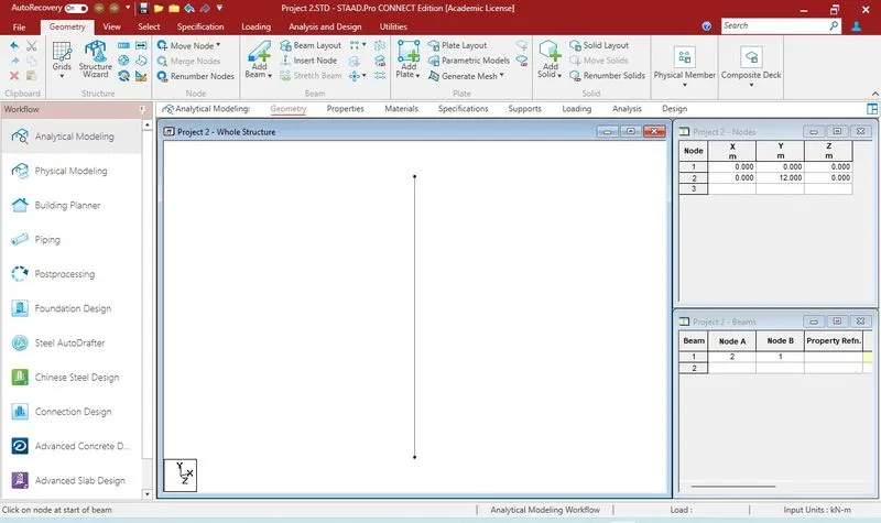
Beam for 12m Pier
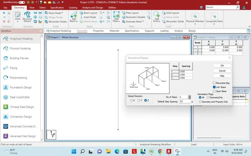
3 more pier added.
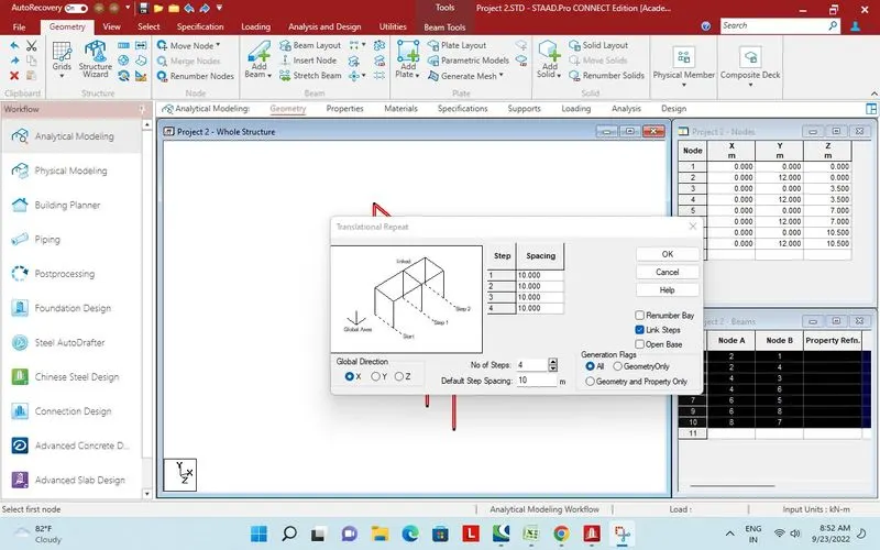
Set of pier addede in x direction by translational repeat.
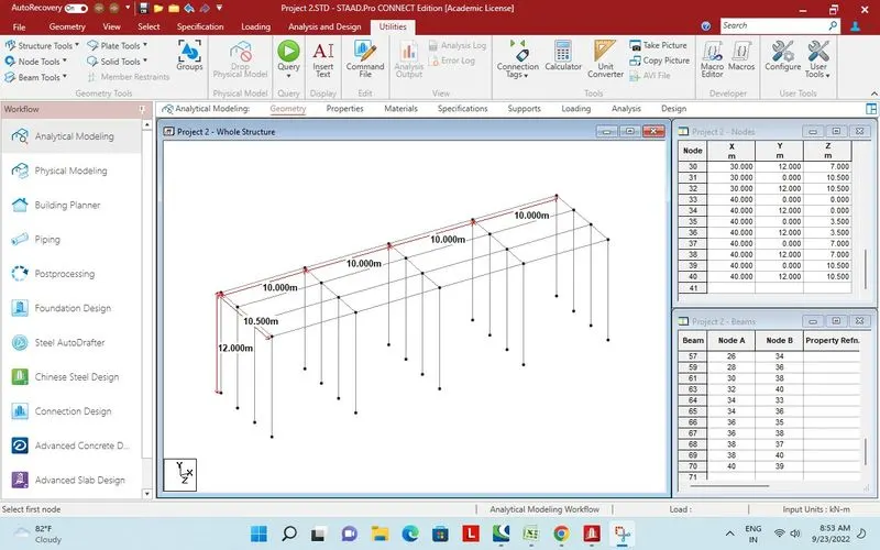
Bridge Geometry as shown.
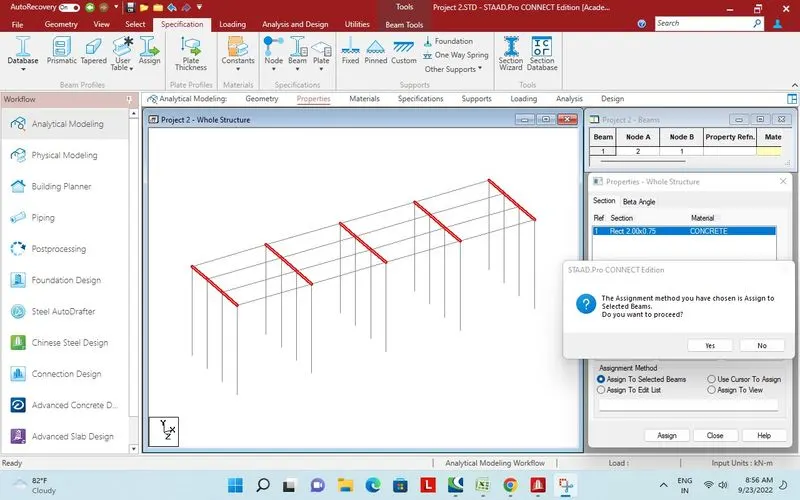
Property assigned to cross beam.
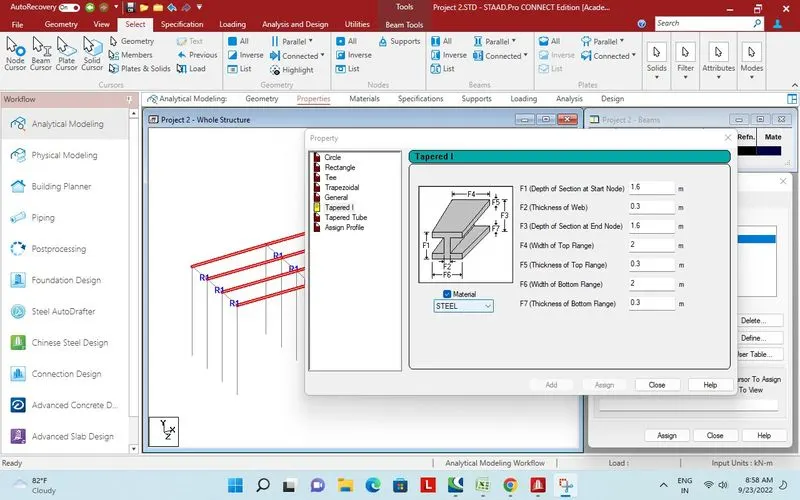
Property assigned to main girder.
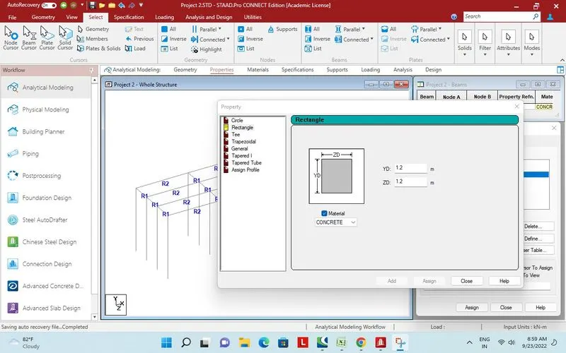
Property assigned to Pier.
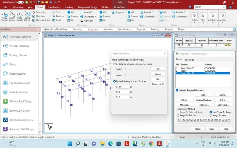
Node selected to paste in x direction at a distance of 0.5m.
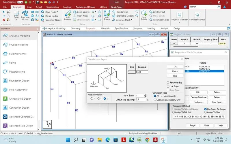
Pair of Nodes in Z direction by translational repeat.
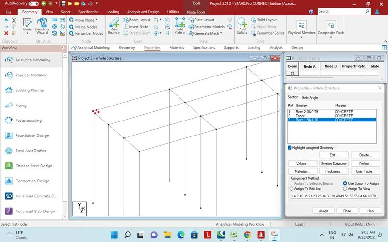 Four nodes for plate creation.
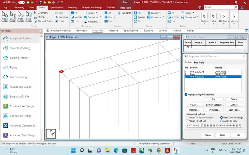 Plate created.
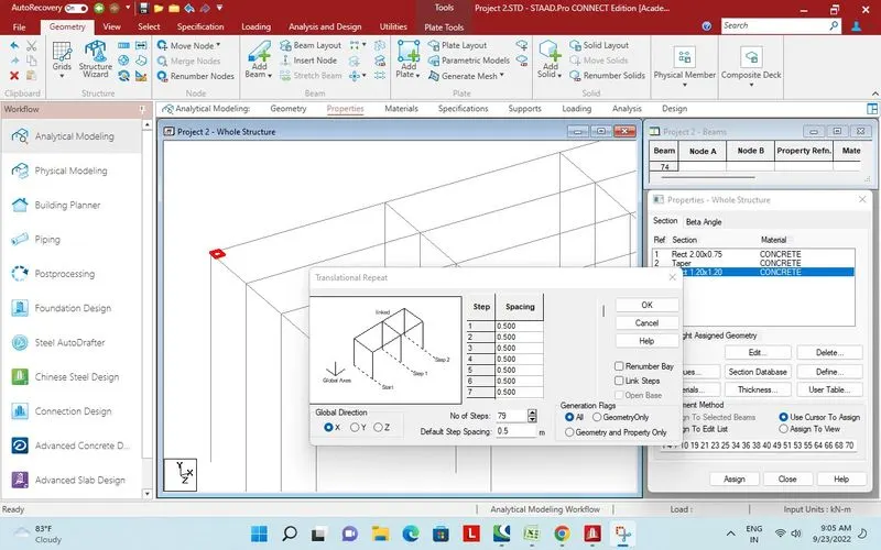 79 plates added in X direction by translational repeat.
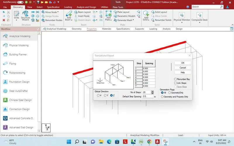
20 set of plates added in Z direction.
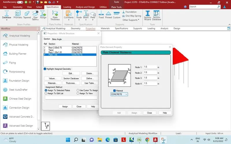
Plate thicknes assigned for Deck.
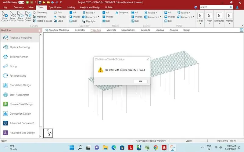
Check for missing property.
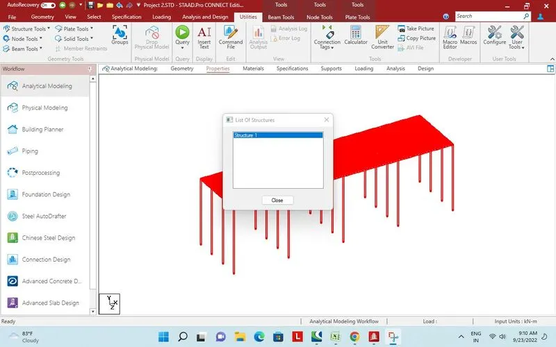
Check for one structure.
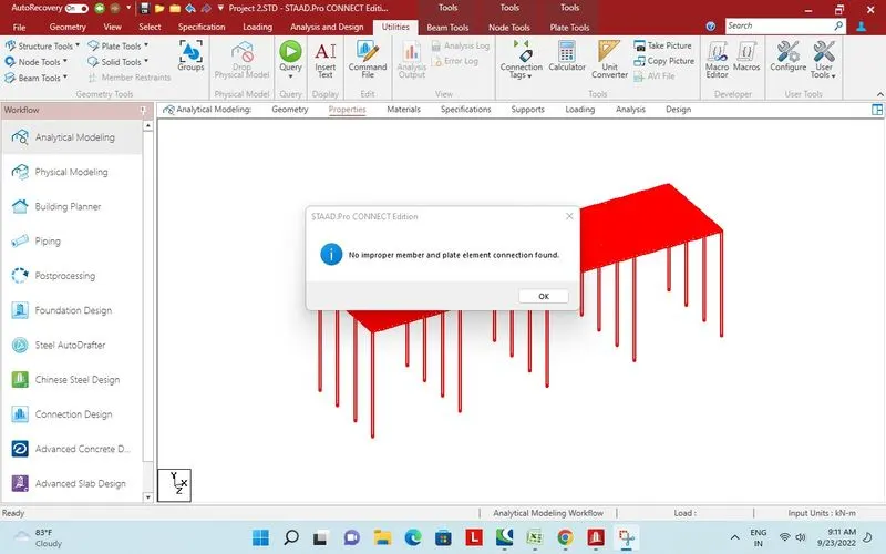
Check for member plate connectivity.
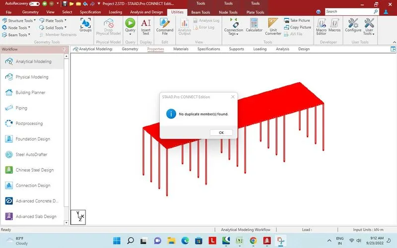
Check for duplicate plate.
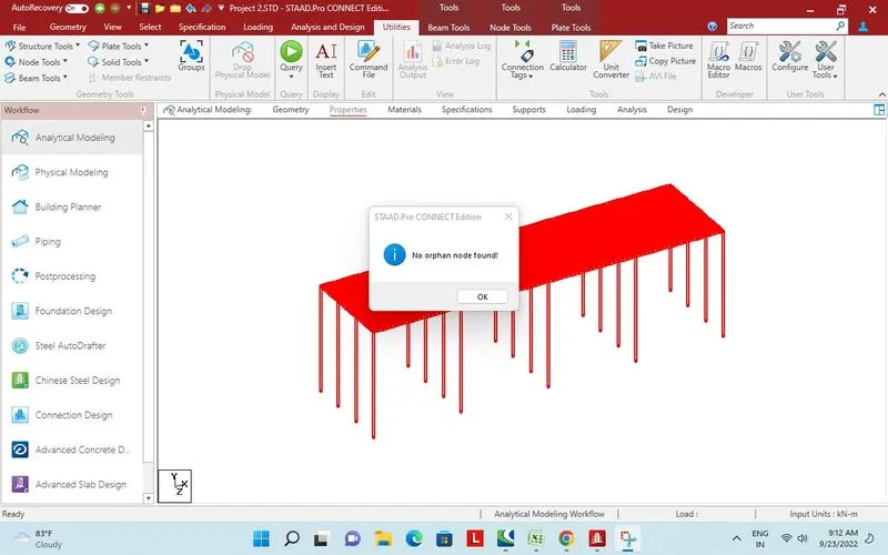
Check for orphan node.
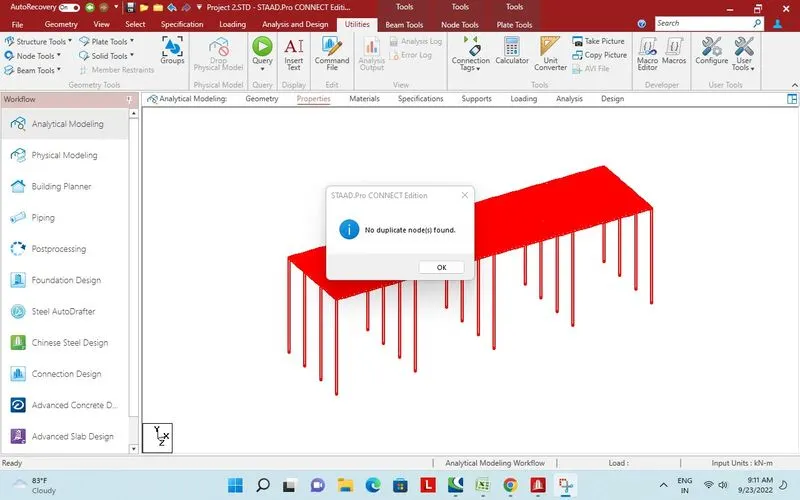
Check for duplicate node.
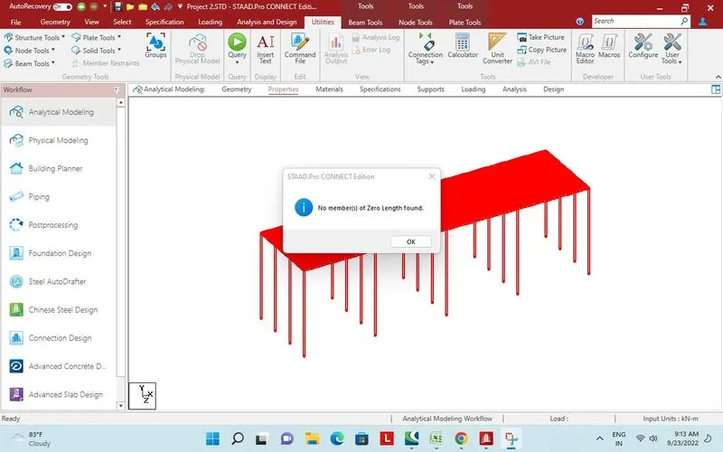
Zero length beam checked.
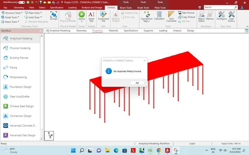
Duplicate plate checked.
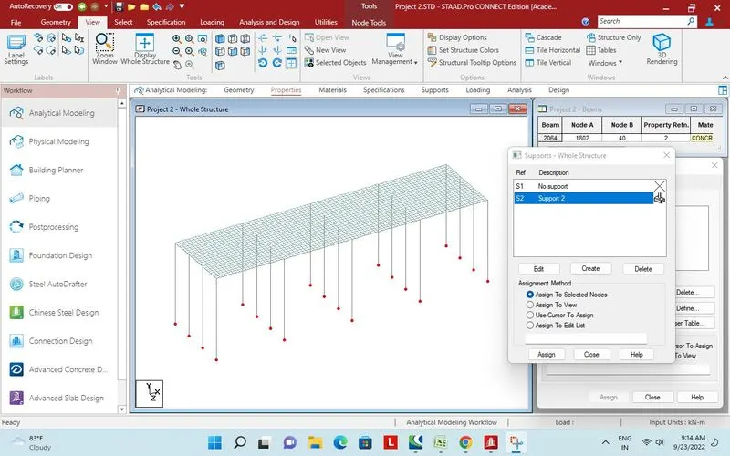
Fixed support assigned.
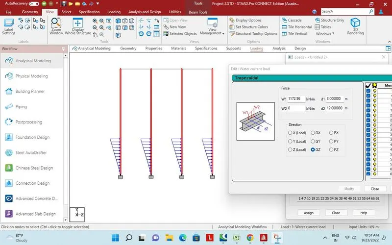
Water current force applied on pier up to H.F.L.
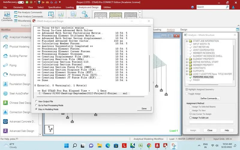
Analysis and design performed successfully.
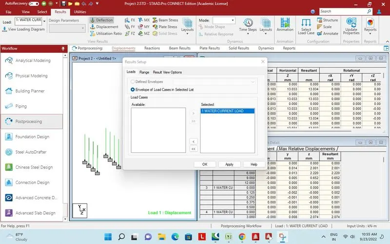
Post proceassing .
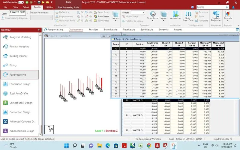
Report section force on pier bending MZ due to water current.
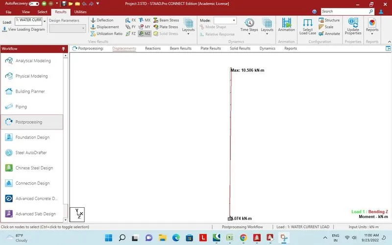
Maximum bending moment on one pier for water current load.
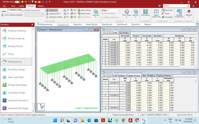
Displacement
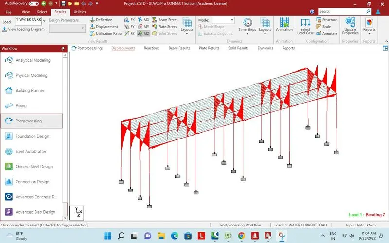
Bending moment MZ due to water current load.
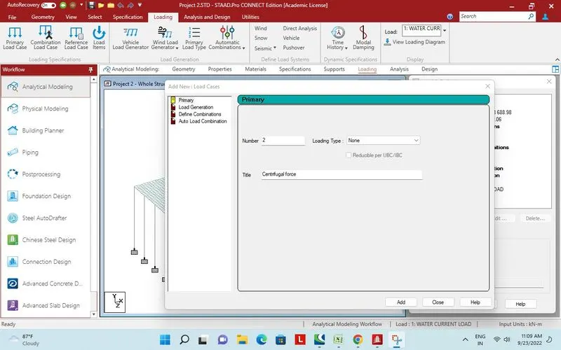
Centrifugal force.
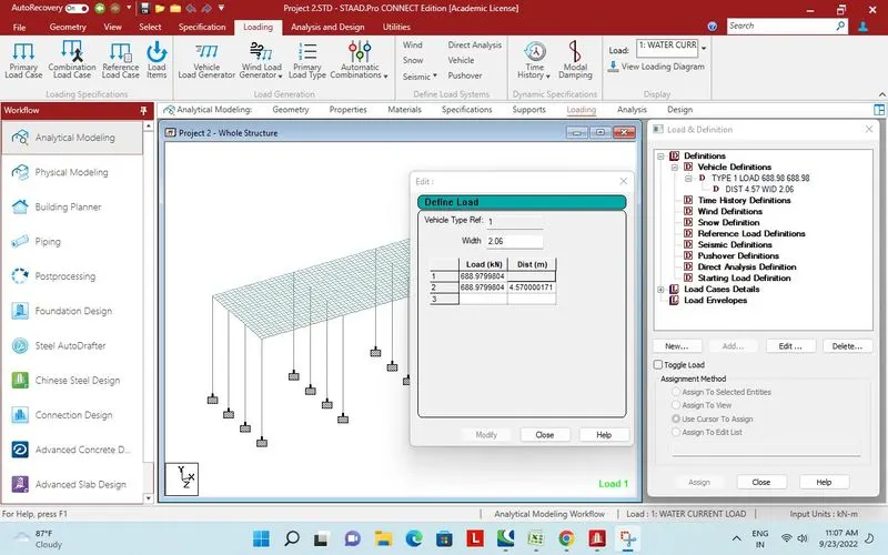
Vehicle defination for centrifugal load
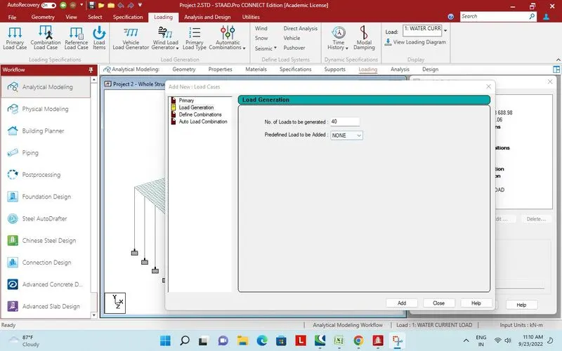
40 No of load generated.
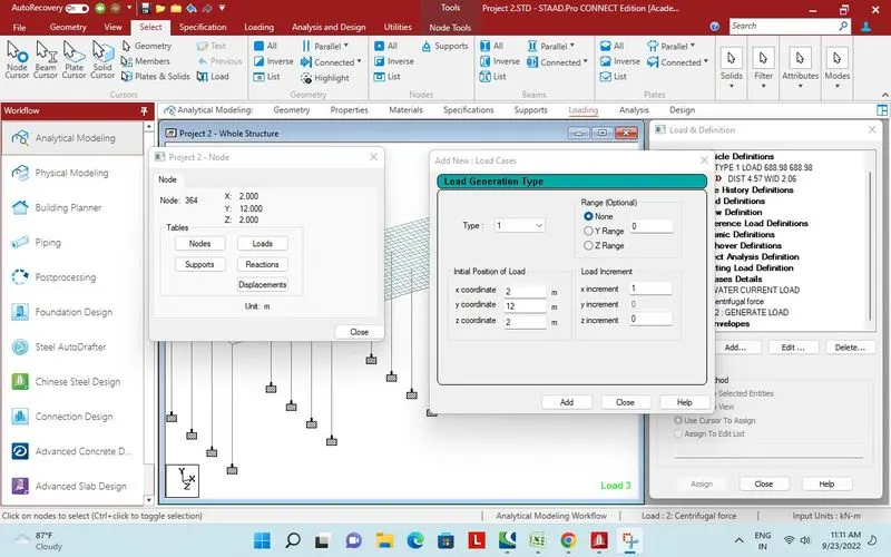
First node selected for vehicle placement with 1m x increment.
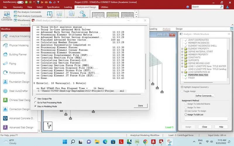
Analysis and design performed successfully.
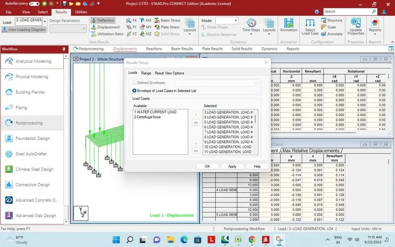
Load generated for centrifugal force selected.
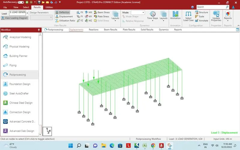
Deflction due to ist place.
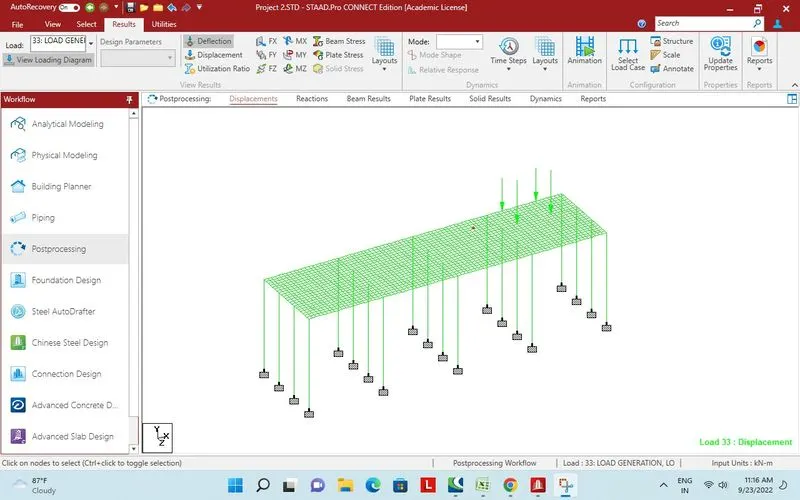
33rd load generation and vehicle position.
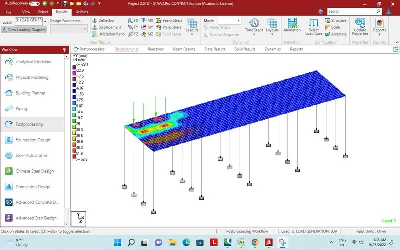
Plate Stress for centrifugal load generated 3
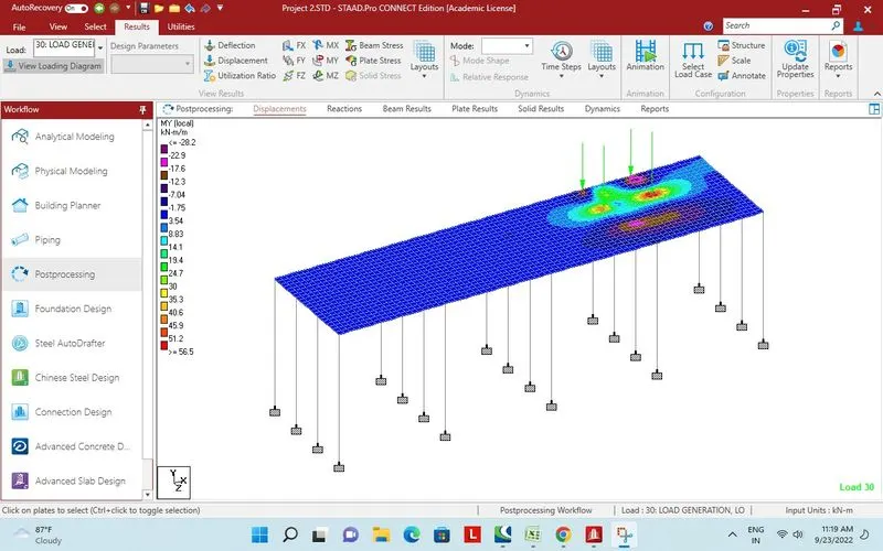
Plate Stress for centrifugal load generated 30
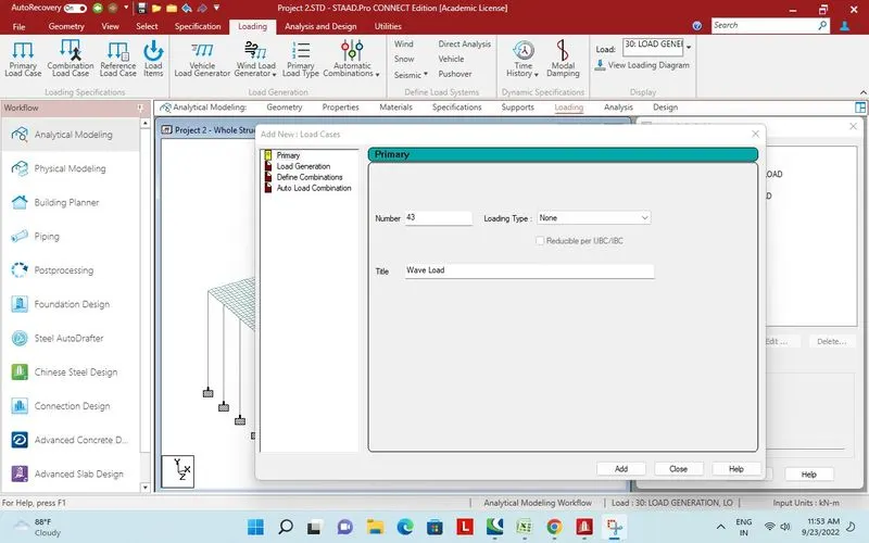
Wave load.
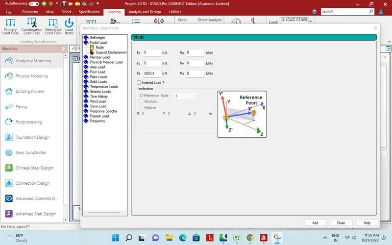
Input in Z direction.
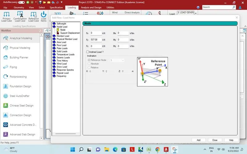
Input in Y direction.
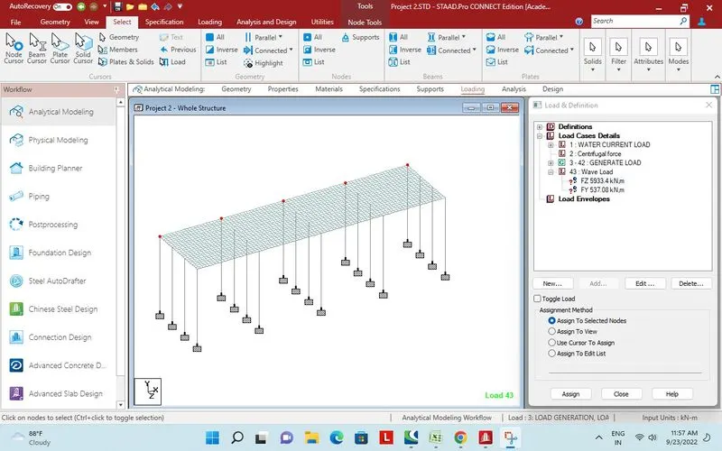
Node selected for horizontal force. Z direction.
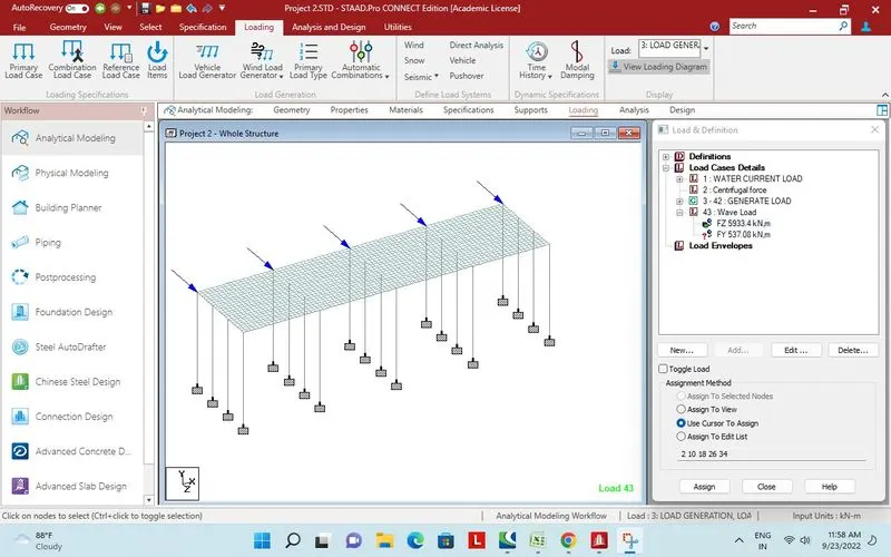
Load in Z direction.
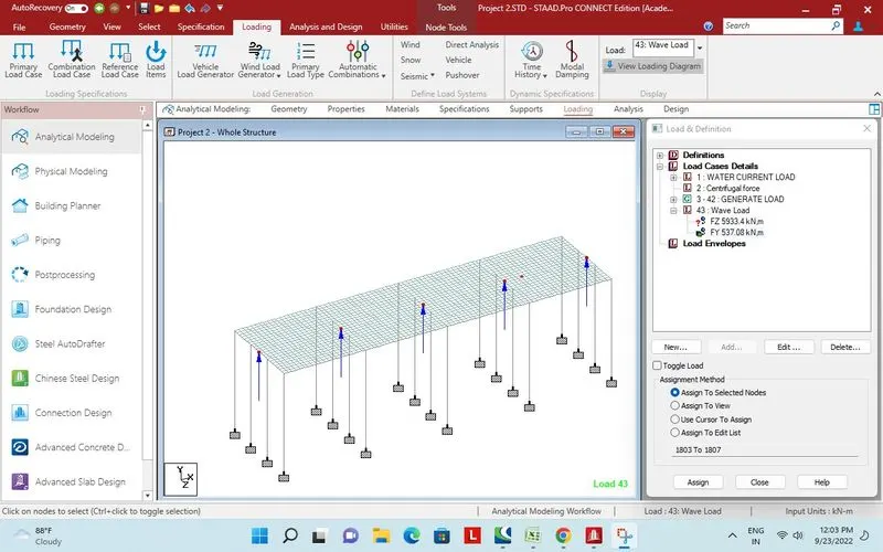
Verticle wave load.
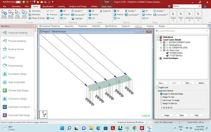
Both the wave load.
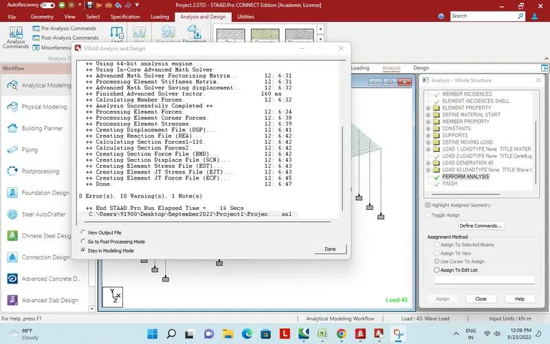
Design and analysis performed successfully.
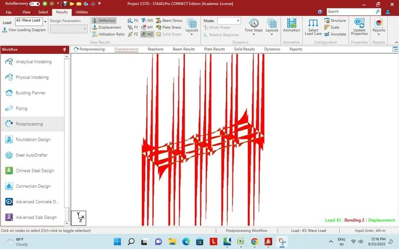
Wave load on Long Girder and Cross girder
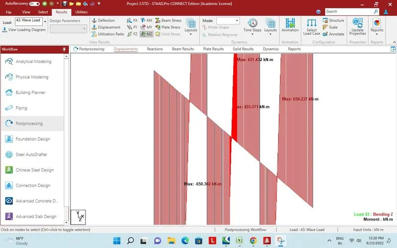
maximum bending moment on Cross girder due to wave load
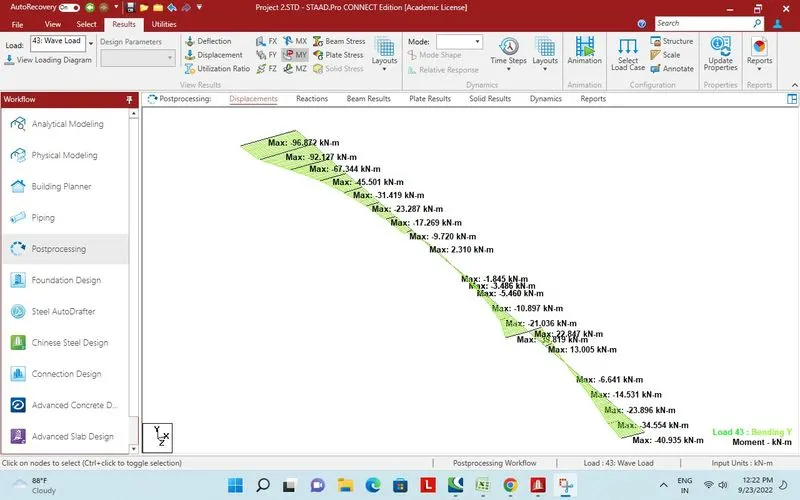
maximum bending moment on Cross girder due to wave load MY
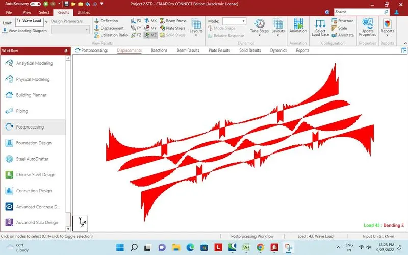
Bending moment on long girder due to wave load
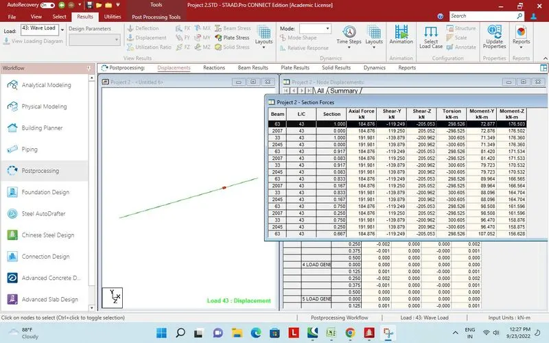
Report section force bending on one long girder
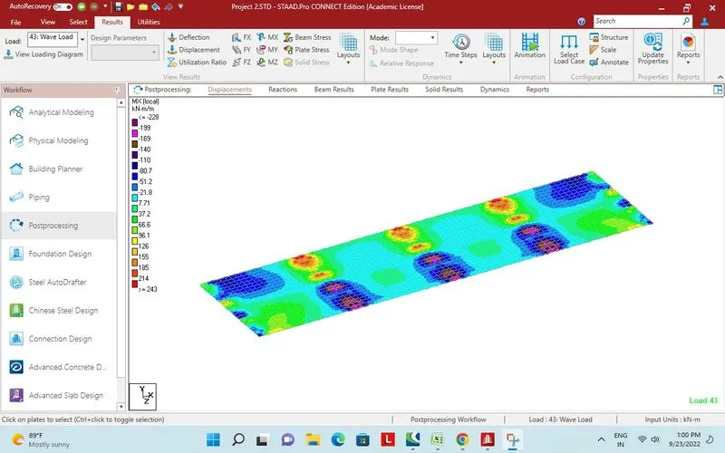
Plate stress MX Local
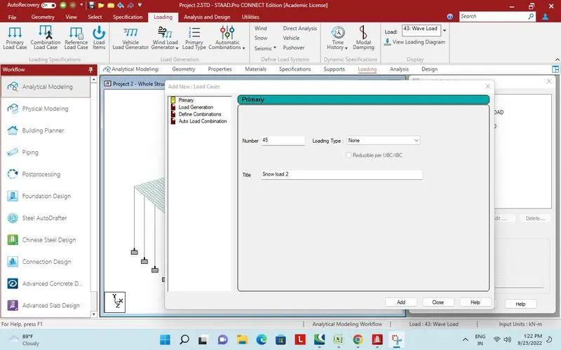
Snow Load
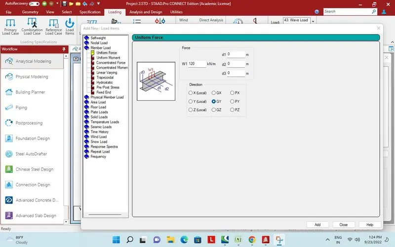
Calculated load.
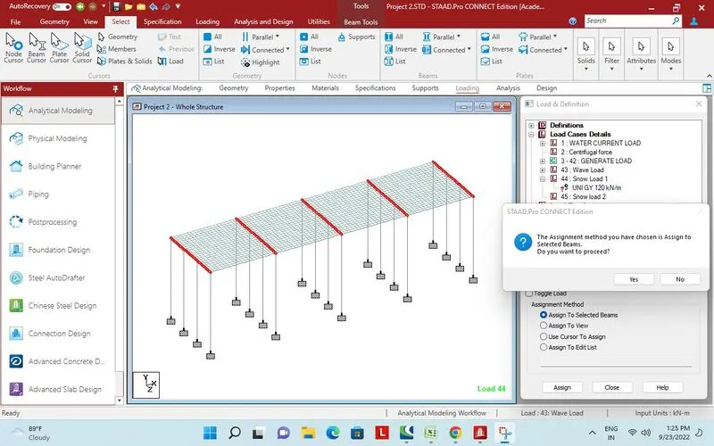
Assigned to cross beam.
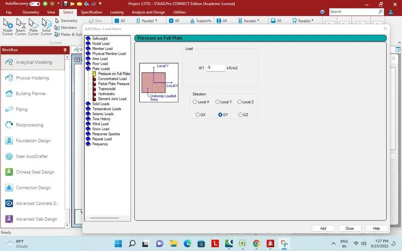
Minimum snow load per meter square.
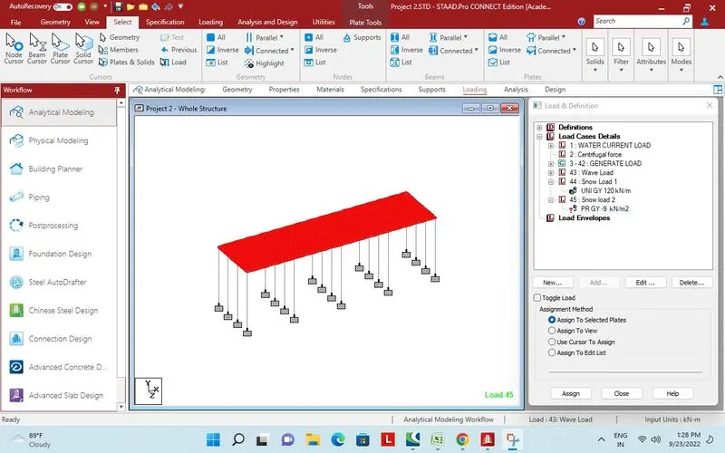
Minimum snow load assigned to deck plates.
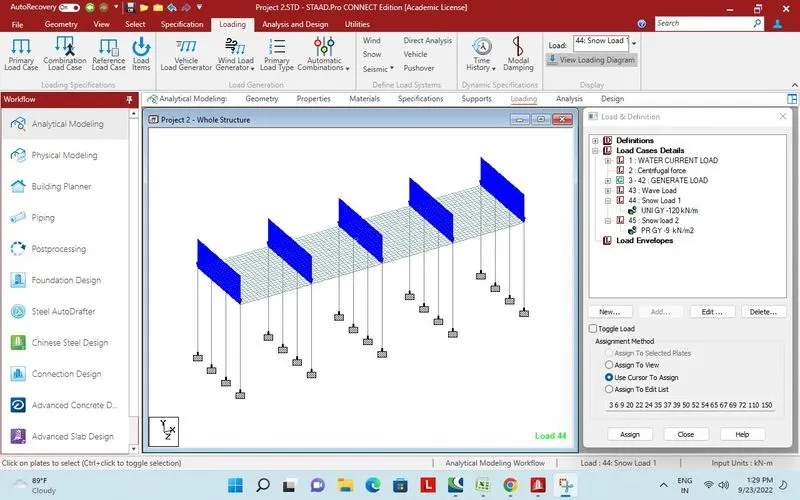
Calculated load kN/m assigned to cross beam.
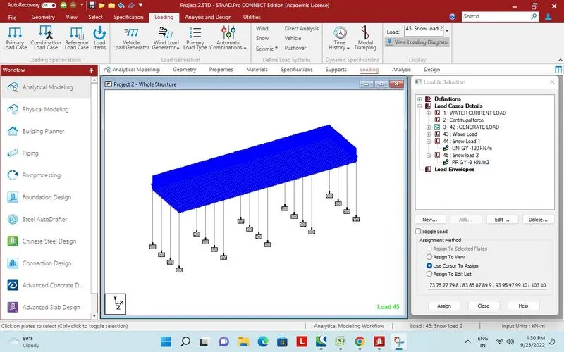
Snow load.
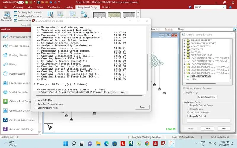
Design and analysis performed successfully.
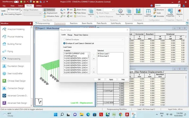
Snow load selected for post processing.
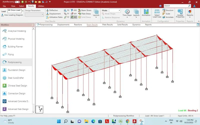
Bending moment due to Snow load case 1.
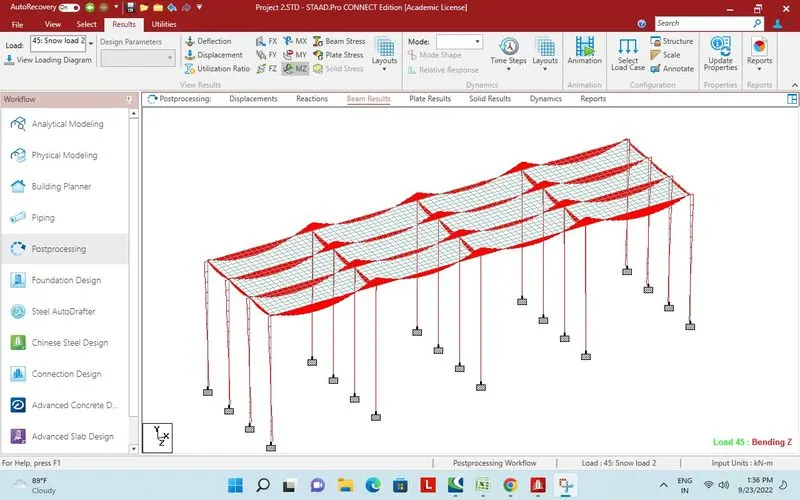
Bending moment due to Snow load case 2.
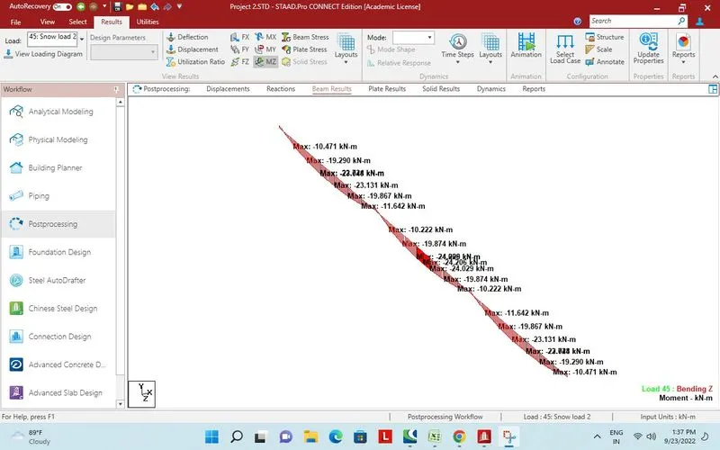
Maximum bending moment on cross beam due to snow load case 2.
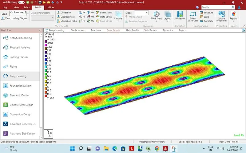
Plate stress MY local due to snow load case 2.
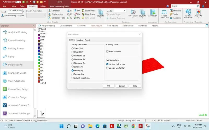
Report.
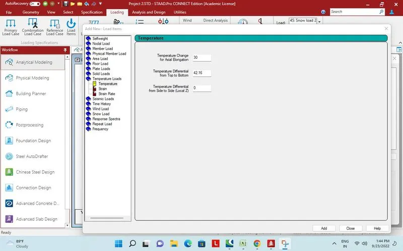
Tempreture load.
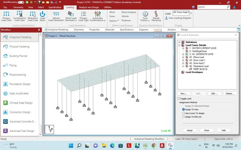
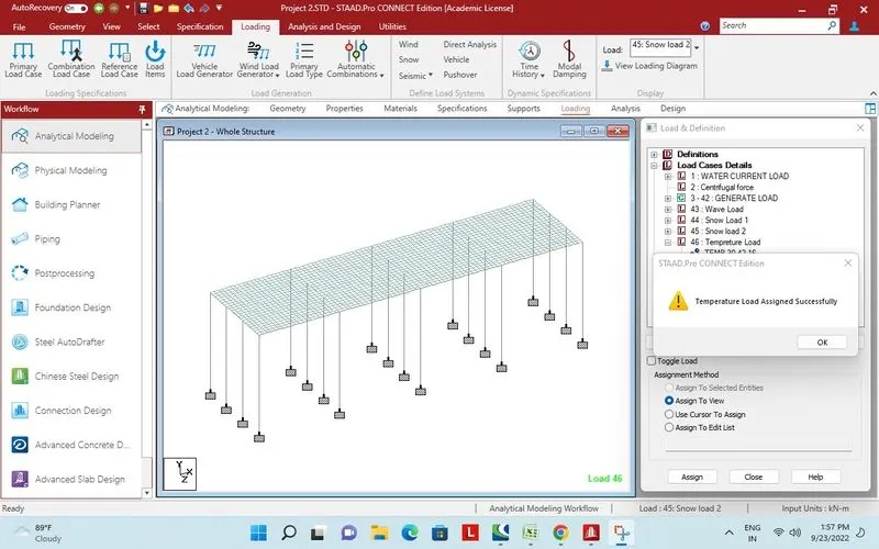
Assigned to whole structure.
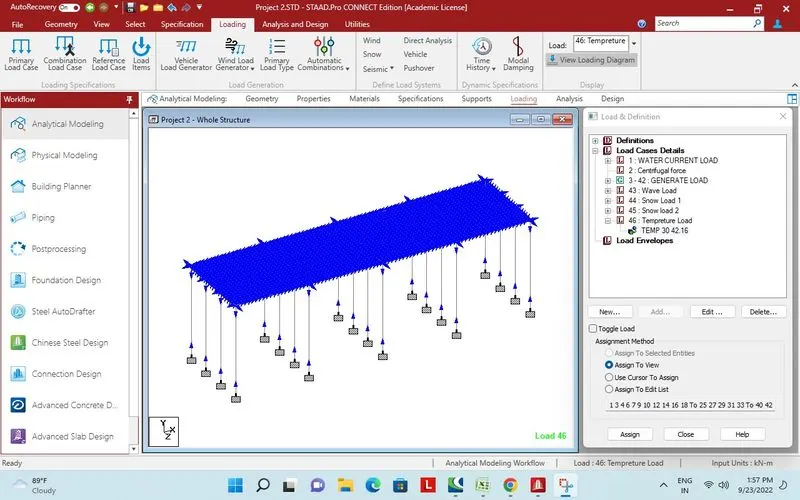
Loading diagram for tempreture load.
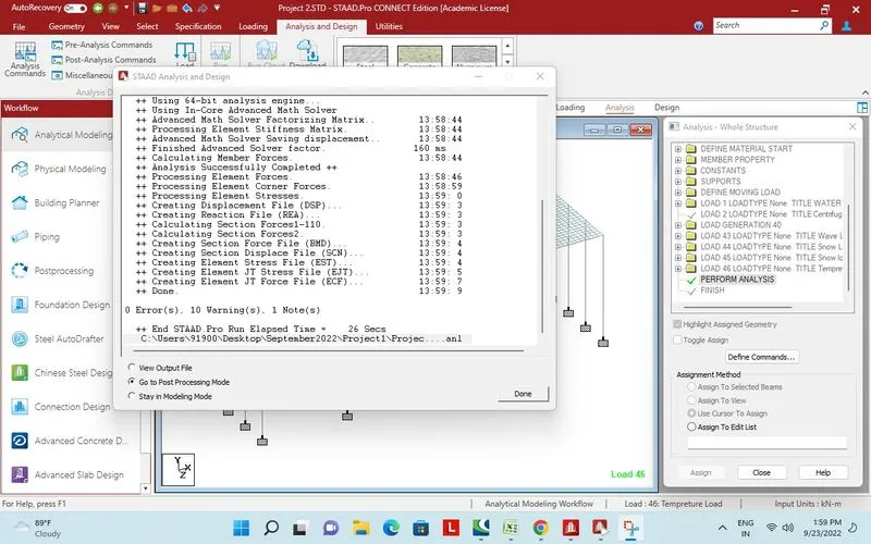
Design and analysis done successfully.
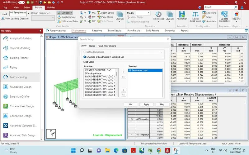
Tempreture load selected for Post processing.
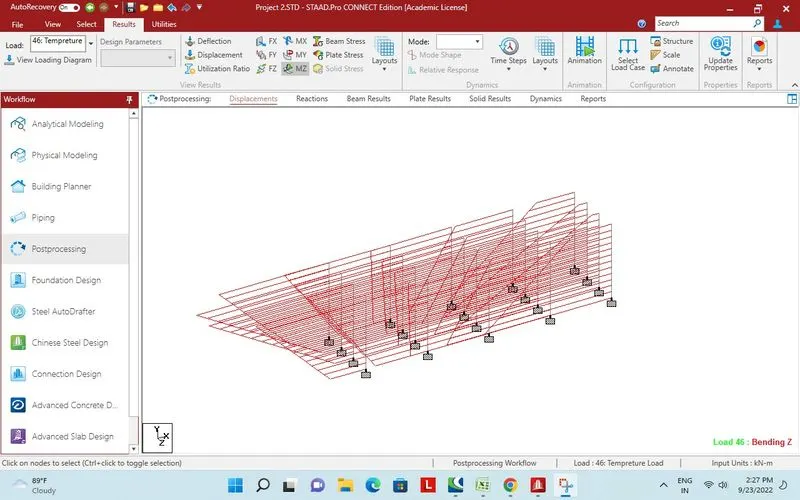
Bending moments on pier.
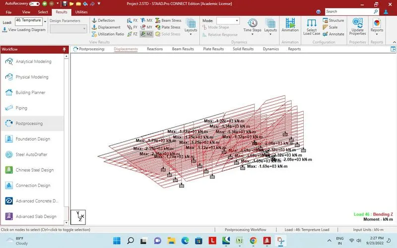
Maximum bending moment annoted on pier.
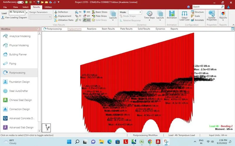
Bending moment MZ on Long girders.
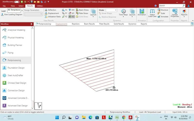
Maximum bending moment on one selected pier.
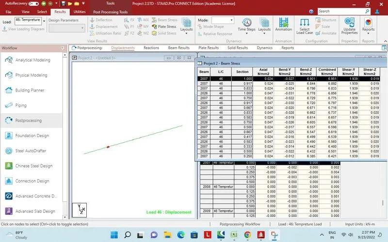
Report Bending moment MZ on Long girder.
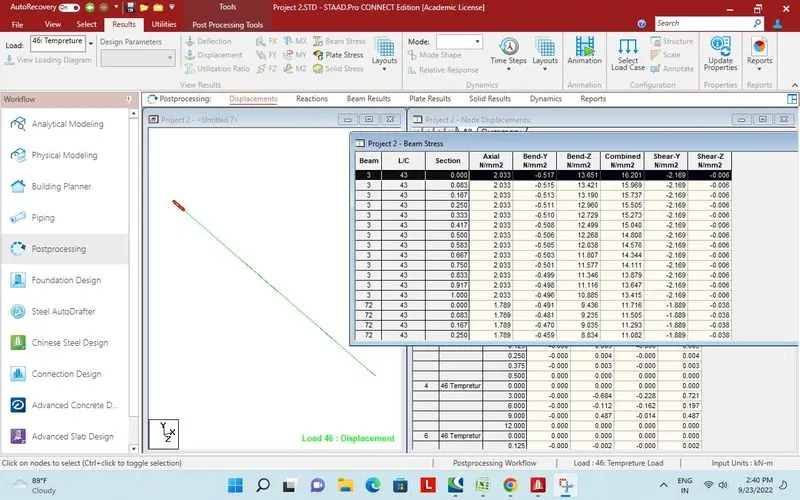
Report Bending mment MZ on Cross Beam.
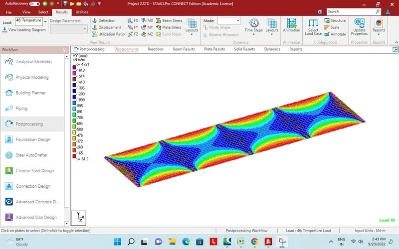
Plate stress MY local due to tempreture load.
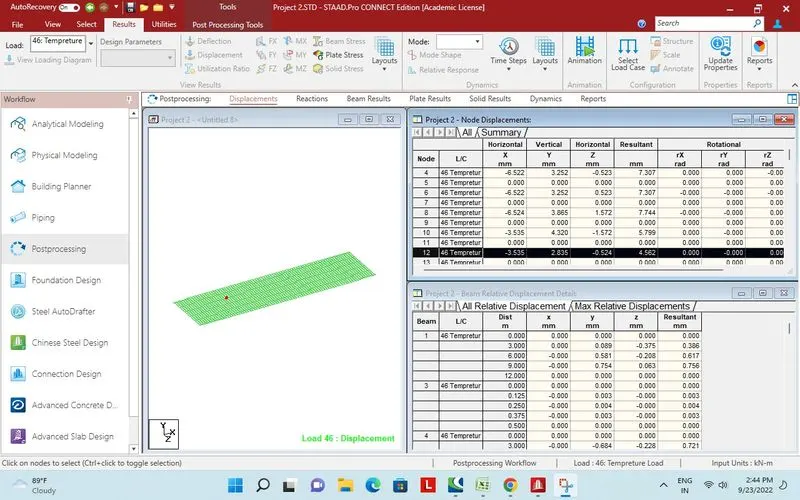
Report Plate stress.
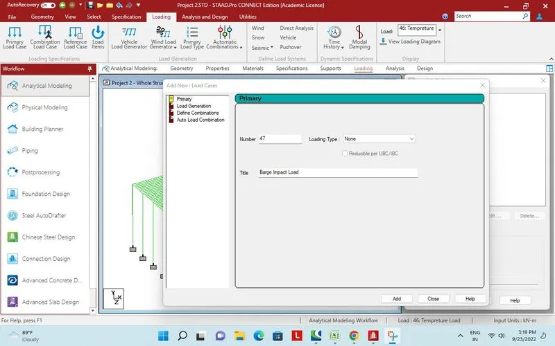
Barge impact load.
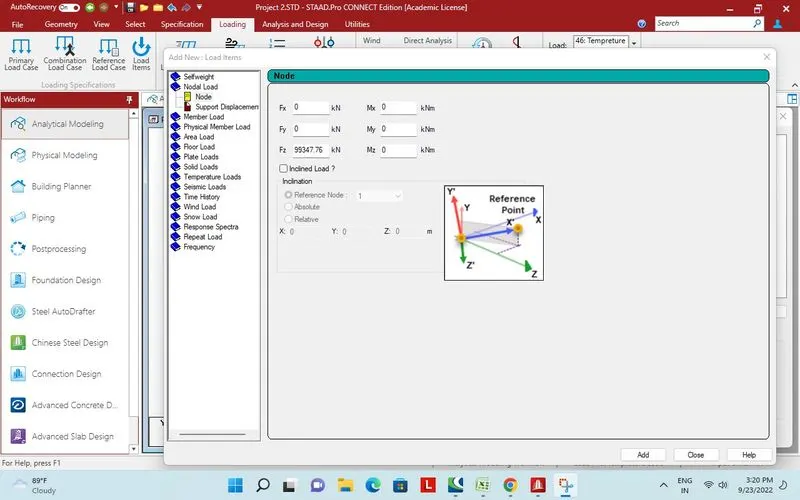
Horizontal load.
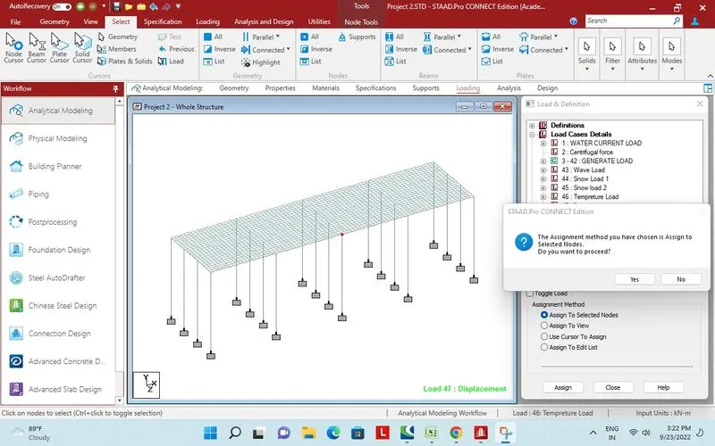
Assigned to mid of superstructure.
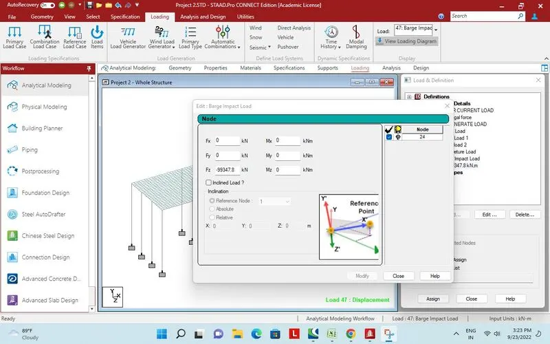
Direction edited.
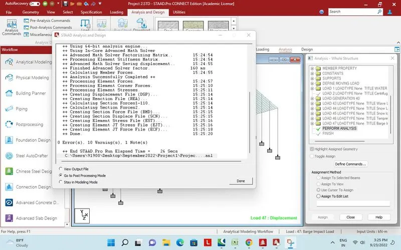
Design and analysis performed successfully.
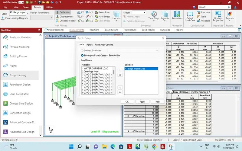
Barge impact load selected for further results.
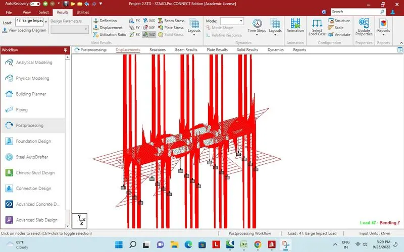
Bending moment MZ.
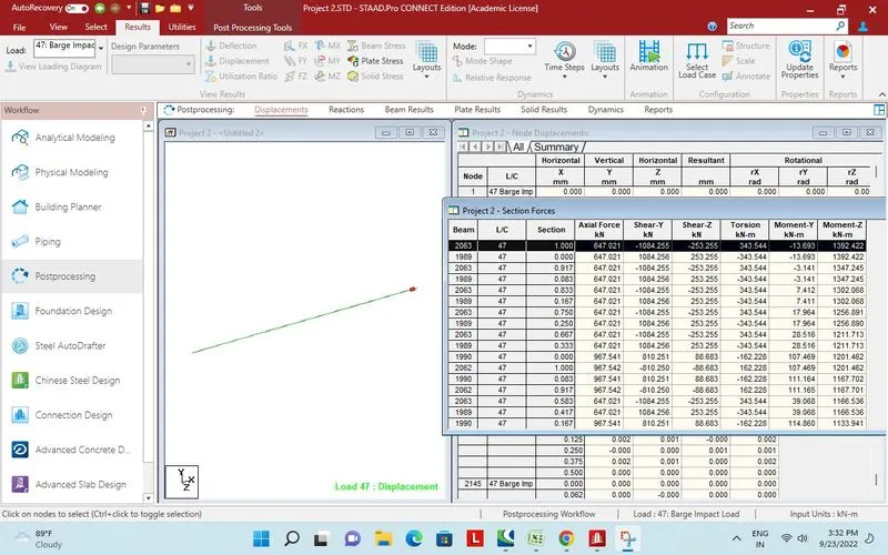
Report of MZ for long girder.
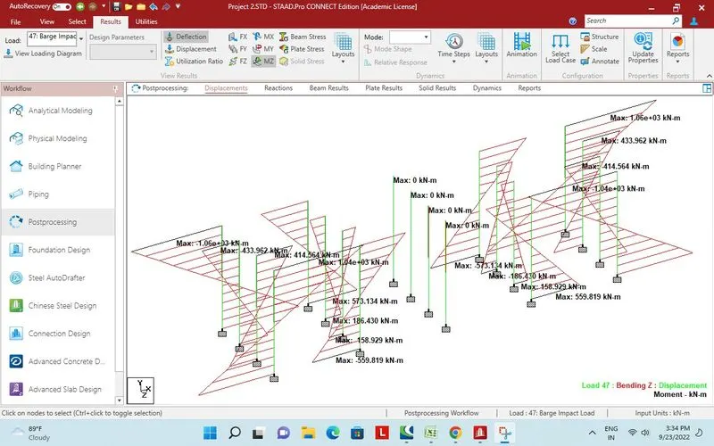
Maximum bending moment on pier.
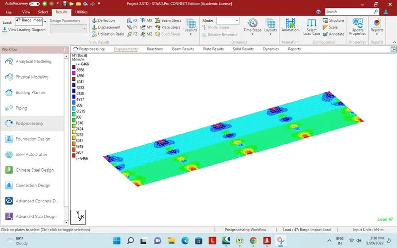
Plate stress MY local.
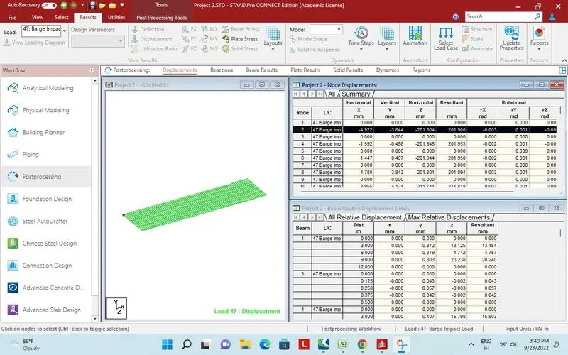
Report plate stress.
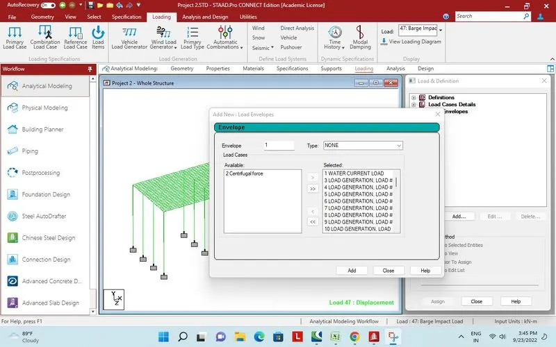
Envloping all loads for design and analysis.
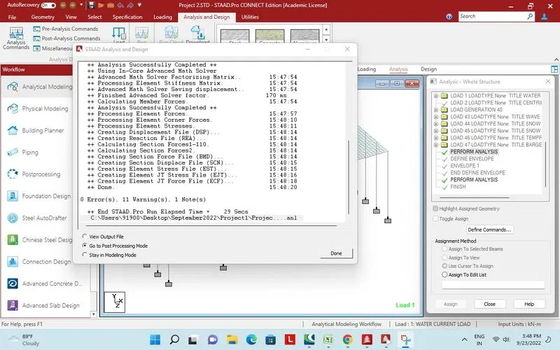
Design and analysis performed successfully.
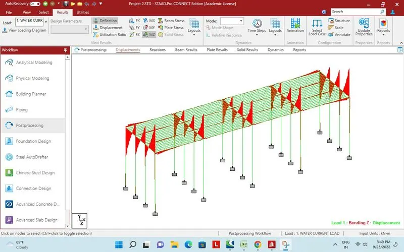
Bending moment MZ.
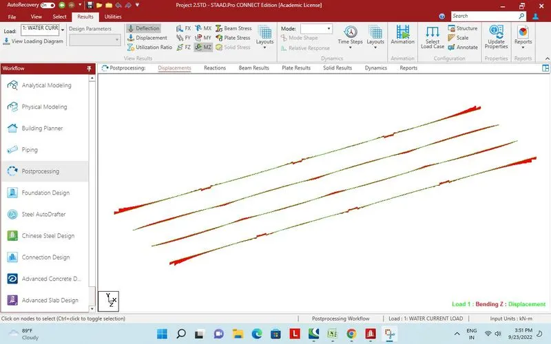
Bending moment MZ on long girders.
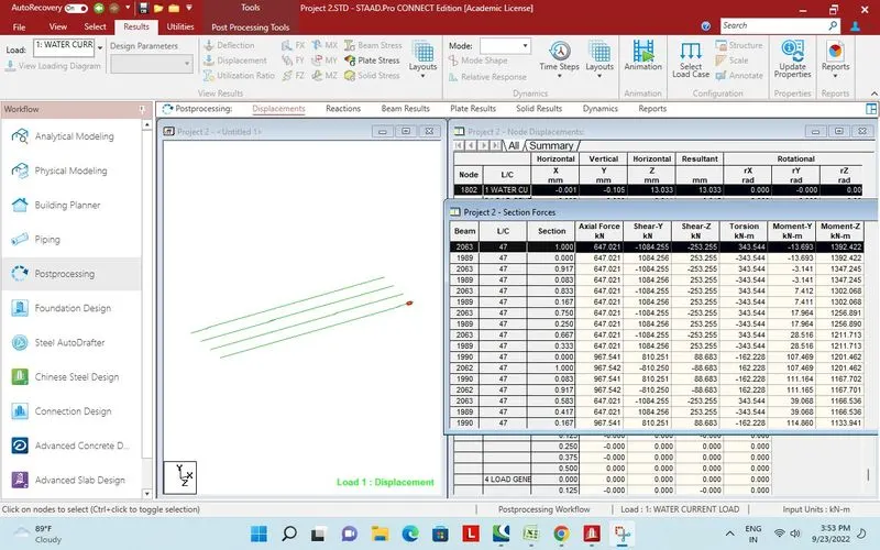
Report section forces on Long girder.
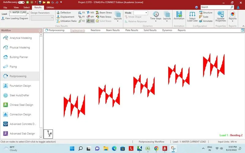
Bending moment MZ on cross girder.
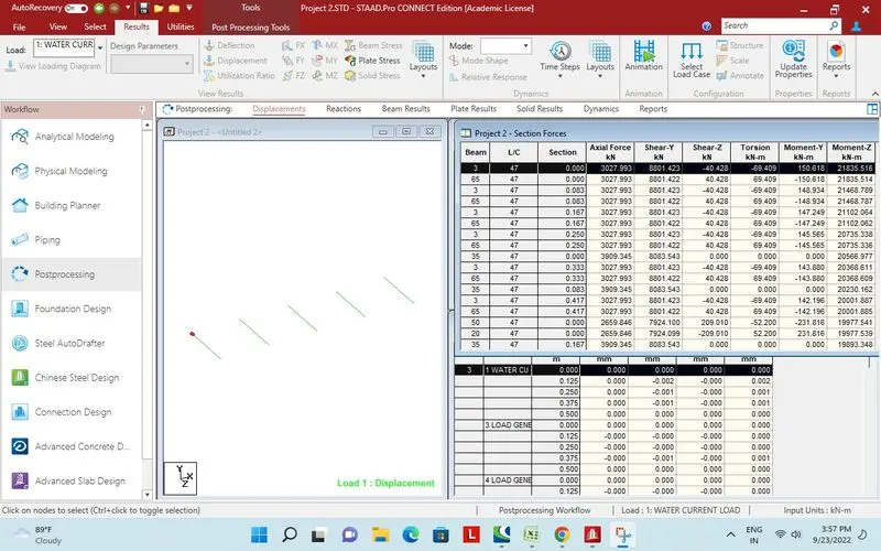
Section forces on cross girder.
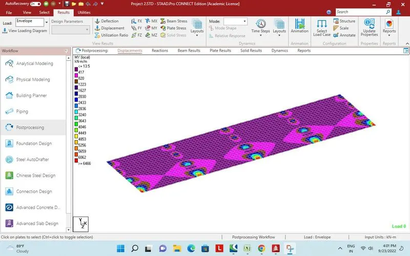
Plate stress on deck MY local.
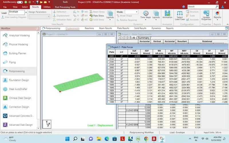
Report plate stress of deck .