Structural meshing of the car spare wheel holder using hypermesh
PROJECT TITLE: Structural meshing of the car spare wheel holder using hypermesh
OBJECTIVE : To mesh the plastic component of a car spare wheel holder with respect to the given quality criteria using hypermesh and assign thickness property.
MODEL GIVEN :
SPARE WHEEL WELL
A spare wheel well, also called spare wheel baffle, is a recessed storage tub located in the trunk of the vehicle. As the name suggests, it houses the spare wheel and tyre, along with the lug wrench and wheel jack. Traditionally, it was made of stamped steel. [1] However, since this part has an important role in the vehicle’s rear structure and crash safety and is also prone to heavy corrosion due to the fact that its underside is always exposed to road elements. Manufacturers started using lighter materials- from aluminium to composite materials at present, reducing both ways in terms of weight and cost.
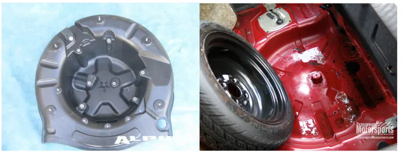
fig: Spare wheel well
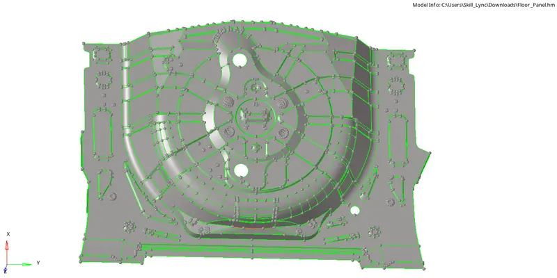
Fig: cad component of car spare wheel holder
- PROCEDURE :
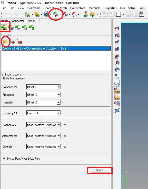
First we will import the given model in hypermesh using import option available under tile bar or else we can just directly import it by choosing open model icon.
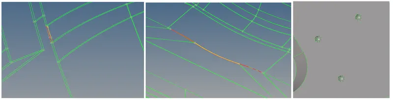
After importing the model in hypermesh the first step we takeup is examining the model for any deformations and missing surfaces. We change the view from "by auto" to "by topo" to see how the connections and geometrical lines like free,shade edges and non-manifold lines later we clearup all those errors which in term we call it as "Geometry or topology cleanup".The below image shows the topology view of imported side door model from this we can observe that there are some free edges appearing,to clearly get a view of all the free edges and missing surfaces we switched to wireframe mode.these are some of the topology errors we found on the parent body
- TOPOLOGY CLEANUP
Topology is how you connect to different surfaces in the geometry which includes
a.free edges which are red in colour say that thay are not connected to anything else
b.shared edge which are green in colour are connected by two surfaces
c.non-manifold/T-junction edge which are yellow in colour resembles that they are connected by three or more than three surfaces.
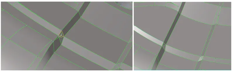
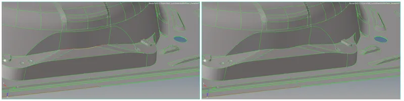
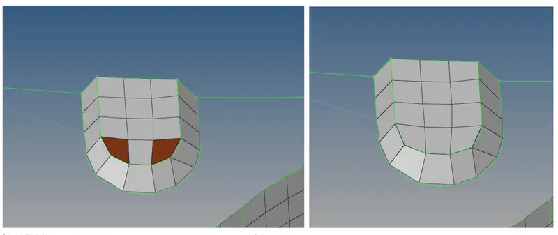
the whole point of Geometry cleanup is correcting the connectivity errors between adjacent surfaces which possibly include free edges or unconnected adjacent surfaces,duplicate surfaces,missing surfaces etc and for having good meshflow and minimum quality errors in the mesh it is better to toggle some lines and make some new cuts on the surface geometry keeping in mind about the minimum and maximum size of the element we are going to mesh.in the below images we can see at some feature areas we toggled and made some new cuts without affecting the geometry.the tools we use here are mostly in quickedit panel.go to geometry-quickedit-toggle edge to remove the lines which we need most probably we will be removing the lines which are at a distance lower than minimum element length later that we use quickedit-splitsurfnode or splitsurf/line tool to make some new cuts.
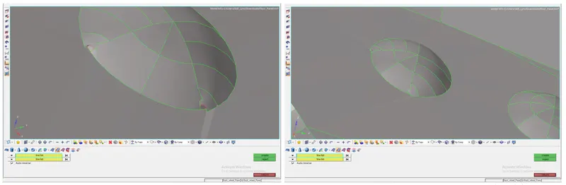
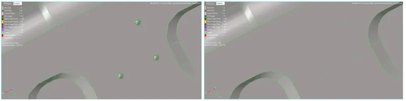
in the below images we can see that we fixed some errors on the geometry and we removed some punch holes which are very small that might fail for low quality element size.after deleting those holes we will use filler surf/2d-spline options to coverup the deleted hole areas.
- EXTRACTION OF MIDSURFACE
Midsurface meshing is opted for components where the geometry thickness is small when compared with the span length of the components, so if you see most of the automotive structures are of sheet metal and plastics, where the length of the component is large when compared to the thickness, hence for this reason we opt for mid surface extraction.
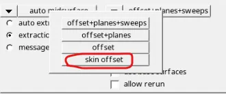
Midsurface extraction can be done by choosing automidsurface option under GEOMETRY-MIDSURFACE tab.we can choose advance techniques for creating midsurface in proper way without any errors or distortion by selecting "extraction options", here we choose SKIN OFFSET as an extraction option to capture midsurface

- There are smooth transitions along the faces. Sometimes, certain non-smooth transitions may be handled by increasing the default geometry feature angle.
- There are no smooth transitions at edges/holes from one face to another one, the transitions should be sharp enough.
- No ribs are present. There should only be one face(plate) in the input.
- No variations in thickness are taken into account.
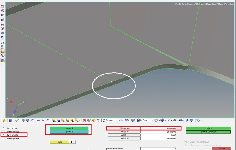
Here the thickness of spare wheel well is about 0.75,so if the midsurface is extracted it should align in ther middle with the distabnce of 0.375 from the top or bottom surface
after extracting the midsurface we crosscheck whether the midsurface is aligned exactly in the middle of the thickness or not by measuring The thickness of the components .here from the below image we can see that the thickness is 0.75 and the extracted midsurface also aligned properly in the middle with the distance of 0.375.
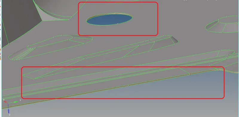
Below figure shows the difference between parent and extracted midsurface. 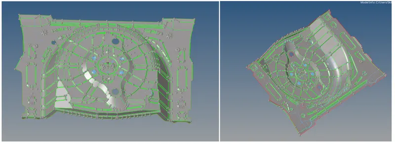
- MESHING
Now we move on to the important step which is meshing.to mesh a surface we have to specify element size, element type and some quality criteria values which is already given to us in the challenge.to enter the criteria values we will select preferences-criteria file settings and enter all the values.
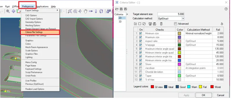
we first mesh the feature areas which are little complex and then proceed with flat areas since we can manage the trias and mesh flow easily on flat surfaces and free edges.there are some of thumb rules which we must follow while meshing to get good result,they are
- features should be captured
- no back to back trias
- there should be connectivity between elements
- no opposite trias
- no trias in fillets or hemmings (can be compromised a little bit at some converging fillet corners)
- no rotational quads
- no trias in corners or edges
while meshing we turn on align and size in mesh options to get proper mesh according to the size and shape of the surface with low quality errors.
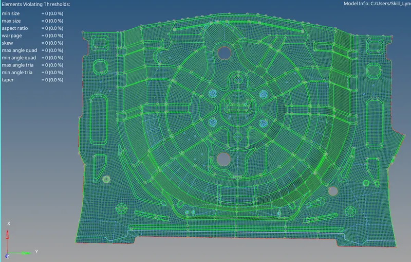
these are some of the images of the model where we meshed with zero quality errors.
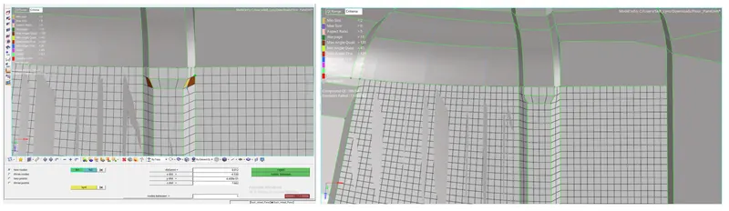
here in this region we found some symmetric regions that we can take advantage of by simply sleecting the elemets where the surfaces are symmetrical and reflect them on other side using tools-reflect option.after reflecting we check the connectivity between elements at the middle.we fix them by replacing the nodes (shortcut:f3) or by shift+f3 which will lets us preview the elements which are not aligned and fix them by pressing "equivalence" button.below image shows that we reflected the centre circular meshed region to other half.
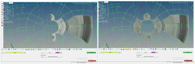
after meshing all the components we remove all the quality errors.mostly at the flat region the minimum and maximum element size failures can be optimized with single click.but at curved or featured areas we should fix it manually since feature capturing is preferred.Mostly we get warpage and max quad angle errors,those are fixed by translating the nodes or by changing the distance from node to node.
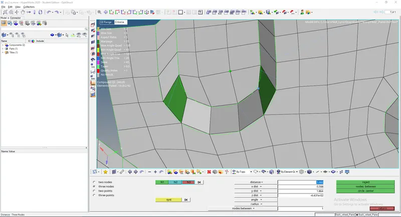
finally we meshed the region with zero quality errors.the final meshed surface is shown below
now we check for tria percentage for that we go to element quality index-qi setting-page3 in that if we see that there is tria percentage of 1.6 which is a good sign.

we need to check the connectivity between elements which might form free edges.to find those free edges we select tools-edges-elements and by selecting the displayed elements we select all the elements appear don screen which we continue to check for connectivity by giving suitable tolerance value and by clicking on preview equivalence we can see where the elements do not have connectivity or alignments.then later by clicking on equivalence they will be resolved, and then we select "find edges" and select all the elements to check the free edges. later we can delete the free edges which are saved in separate component.the below image shows the free boundary edges other than that there are no free edges anywhere on the component.
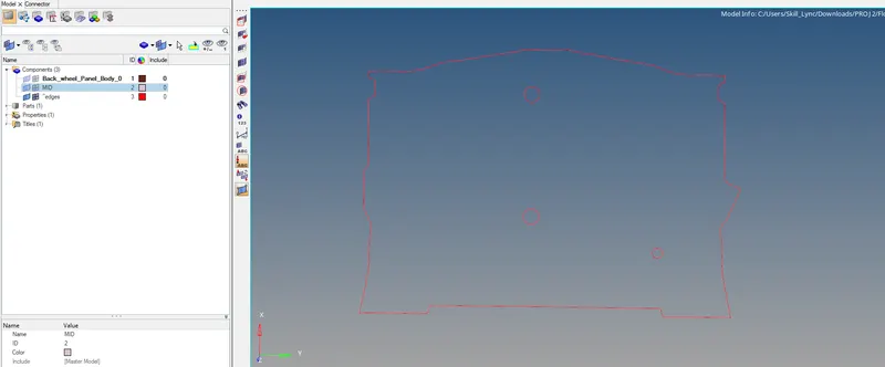
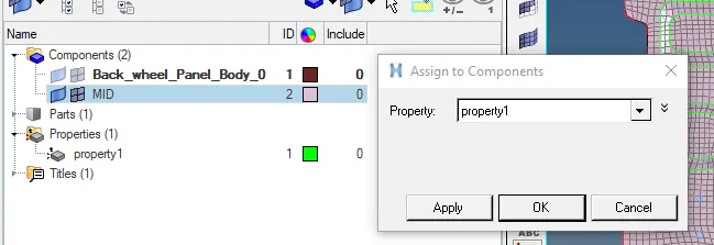
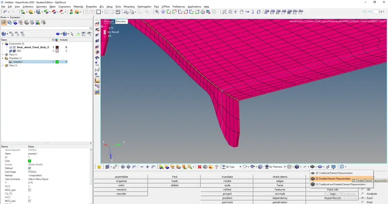
Now we are going to assign thickness to the shell elements which is 0.75,we will create a property and indiacte thickness value of 0.75.later we will assign it to the component where mesh is present here the below image shows the image of assigned property to the component.
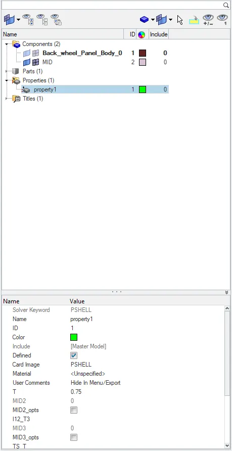
To see the thickness we assigned we have to turn on "2d detailed element representation" option which is available under workspace.
RESULT :
1.Midsurface is extracted successfully from the given spare wheel well component.
2.Deployed 2D mesh with good mesh flow which is having zero quality failures and low tria percentage.
3.Assigned thickness property to shell elements.