Project 2 - 3D CFD modelling of Air cooling system and liquid cooling system for battery thermal management
Objective:3D CFD modelling of Air cooling system and liquid cooling system for battery thermal management.
Problem Statement
Comparative study of thermal performance of air-cooled and liquid-cooled battery modules.Module consists of 5 prismatic cells enclosed in an aluminium enclosure.Worst case scenario -cell soaked at 45⁰C ambient with heat generation corresponding to 0.5 C discharge.Inlet temperature of 20 ⁰C for both air and liquid.
Theory:
Comparative study of thermal performance of air-cooled and liquid-cooled battery modules.
A comparative study of the thermal performance of air-cooled and liquid-cooled battery modules is essential for understanding the advantages and disadvantages of each cooling method. Both approaches are commonly used in electric vehicle (EV) and energy storage systems to manage the operating temperature of batteries. Let's compare them across various aspects:
- Heat Dissipation Efficiency:
- Air-Cooled: Air cooling relies on fans and heat sinks to dissipate heat. It is generally less efficient at dissipating heat compared to liquid cooling.
- Liquid-Cooled: Liquid cooling uses a heat transfer fluid (typically water or a specialised coolant) to remove heat. This method is more efficient at dissipating heat compared to air cooling.
- Temperature Control:
- Air-Cooled: Temperature control in air-cooled systems can be more challenging, especially in extreme environmental conditions. The cooling rate is influenced by factors like airflow and ambient temperature.
- Liquid-Cooled: Liquid cooling provides better temperature control as the coolant can be precisely regulated. It can maintain batteries within a narrower temperature range, which is critical for battery performance and lifespan.
- Uniformity of Cooling:
- Air-Cooled: Air cooling may lead to uneven cooling across the battery module, especially if there are dead spots where airflow is limited.
- Liquid-Cooled: Liquid cooling can provide more uniform cooling as the coolant can be circulated evenly throughout the module.
- Coolant Leakage Risk:
- Air-Cooled: There is no risk of coolant leakage since there is no liquid coolant used.
- Liquid-Cooled: Liquid-cooled systems carry a risk of coolant leakage, which, if not managed properly, can damage the battery or other components.
- System Complexity:
- Air-Cooled: Air-cooled systems are generally simpler in design and easier to maintain. They do not require a complex network of tubes and pumps.
- Liquid-Cooled: Liquid cooling systems are more complex, requiring pumps, heat exchangers, and tubing. Maintenance and potential coolant leaks can add to the complexity.
- Energy Efficiency:
- Air-Cooled: Air cooling is generally less energy-efficient because fans need to operate continuously to maintain cooling.
- Liquid-Cooled: Liquid cooling systems can be more energy-efficient as they only need to circulate the coolant when necessary to maintain temperature.
- Cost:
- Air-Cooled: Air cooling systems are usually less expensive to install and maintain.
- Liquid-Cooled: Liquid cooling systems tend to have a higher upfront cost due to the complexity of the system and the need for additional components.
- Scalability:
- Air-Cooled: Air cooling is more straightforward to scale for larger battery systems.
- Liquid-Cooled: Liquid cooling may become more practical and efficient as the size of the battery system increases.
The choice between air-cooled and liquid-cooled battery modules depends on various factors, including the specific application, cost constraints, desired temperature control, and system complexity. While air cooling is simpler and more cost-effective for smaller systems or less demanding applications, liquid cooling is often preferred for larger, high-performance systems where precise temperature control and heat dissipation are critical for battery longevity and performance.
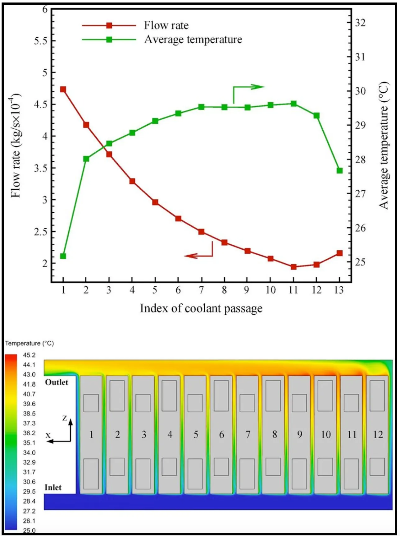
Comparative study of thermal performance of air-cooled and liquid-cooled battery modules.Module consists of 5 prismatic cells enclosed in an aluminium enclosure.Worst case scenario -cell soaked at 45⁰C ambient with heat generation corresponding to 0.5 C discharge.Inlet temperature of 20 ⁰C for both air and liquid.
Scenario Details:
- Ambient Temperature: 45°C
- Heat Generation Rate: Corresponding to 0.5 C discharge
- Initial Inlet Temperature (for both air and liquid): 20°C
Air-Cooled Battery Module:
- Temperature Gradient:
- The air-cooled module will rely on fans and heat sinks to dissipate heat. It will draw in ambient air at 45°C and attempt to cool the cells down to a safe operating temperature.
- Due to the high ambient temperature, achieving a significant temperature gradient may be challenging. The cells might not be adequately cooled, potentially leading to high operating temperatures.
- Cooling Efficiency:
- Air cooling efficiency depends on the rate at which heat can be transferred to the surrounding air. In this high-temperature scenario, the cooling efficiency may be limited, and the cells could operate closer to their upper temperature limits.
- Uniformity of Cooling:
- Air cooling may provide less uniform cooling across the cells, as some cells may receive better airflow than others.
- Energy Consumption:
- Air cooling systems will consume energy continuously to maintain airflow and cooling. This could result in a higher energy consumption compared to liquid cooling.
Liquid-Cooled Battery Module:
- Temperature Control:
- Liquid cooling can be more effective in this scenario because the coolant temperature can be maintained at or below the desired cell operating temperature (typically around 25-35°C).
- The liquid coolant can absorb and carry away the heat more efficiently than air.
- Uniformity of Cooling:
- Liquid cooling is capable of providing more uniform cooling as the coolant can be evenly circulated around the cells.
- Coolant Temperature:
- The coolant's temperature can be controlled precisely to ensure that all cells stay within a safe operating range.
- Energy Consumption:
- Liquid cooling systems can be designed to operate more efficiently, as the coolant circulation can be controlled based on the actual heat load, reducing energy consumption.
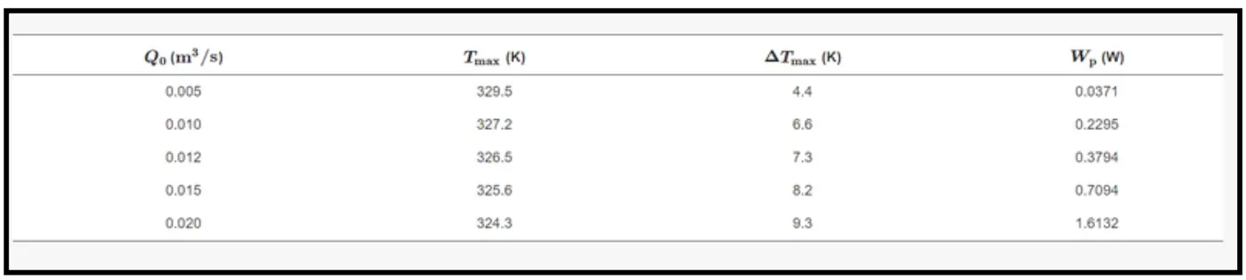
For the parallel air-cooled BTMS, the values of Tmax and ΔTmax strongly depend on the operation parameters and the structure parameters of the system. The operation parameters include the discharge rate, the inlet air temperature (T0) and the inlet airflow rate (Q0). The structure parameters include the cell spacing (d0) and the angles of the divergence plenum and convergence plenum (θ1 and θ2). In the following content, the influences of these parameters on the cooling performance of the BTMS are explored using the CFD method. Finally, an optimisation strategy is introduced to obtain the optimal parameters.
Influence of the Discharge Rate:-
The heat generation rate of the battery cell depends on the discharge rate. This section considers various discharge rates as 3-current (3C), 4-current (4C), 5-current (5C) and 6-current (6C) and conducts the CFD calculation respectively. It can be observed that Tmax and ΔTmax both increase as the discharge rate increases. In the BTMS, the temperature difference of the air is not large, so the properties of the air can be treated to be independent of temperature. That means the temperature calculation is decoupled from the velocity calculation. Therefore, the change of discharge rate does not affect the flow field in the BTMS. When the discharge rate increases, the discharge current increases and the heat generation rate increases, which will increase the temperature and the temperature difference of the battery pack.
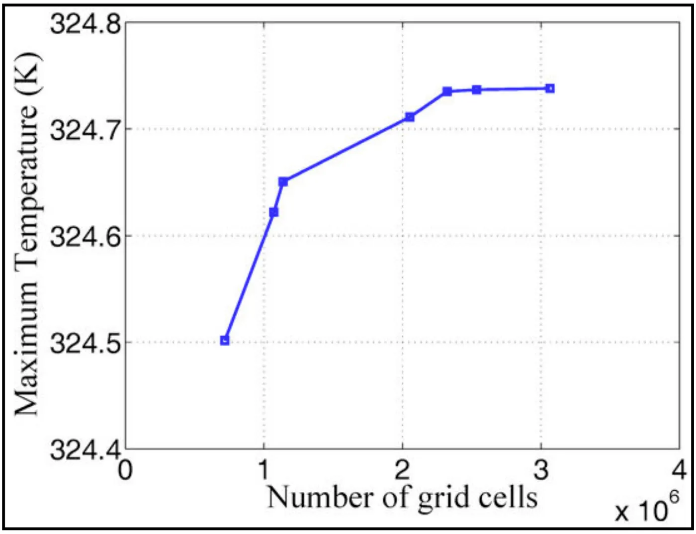
Therefore, reducing the discharge rate can help to reduce Tmax and ΔTmax of the battery pack. In reality, when the EV starts or accelerates, more power is needed from the battery pack, and the discharge rate is larger. In these situations, the temperature rise and the temperature difference of the battery pack are large, and thermal runaway is likely to be induced. However, the power consumption of the battery pack usually depends on the properties of the battery cell and the actual power requirement of the EV. The discharge rate cannot be controlled effectively. Therefore, reducing the discharge rate is not a realisable way to reduce the temperature of the battery pack.
It can be observed that the maximum temperature rise (Tmax−T0) and the maximum temperature difference ΔTmax are independent of T0. Note that T0 does not affect the flow field in the BTMS. When T0 is increased or decreased by a certain value, the whole temperature field is increased or decreased by the same value. In reality, the inlet air temperature can be reduced through refrigeration equipment, such as the air conditioner. However, reducing the inlet air temperature can only reduce the absolute temperature, but cannot reduce the temperature difference of the battery pack. Moreover, the introduction of the refrigeration equipment will require additional power consumption. Therefore, it can be concluded that reducing the inlet air temperature is not an effective way to reduce the temperature difference of the battery pack.
Meanwhile, the velocities in the cooling channels increase as d0 decreases, which will increase the convective heat transfer coefficient on the surface of the battery cells and reduce the cell temperatures. In the parallel air-cooled BTMS, the pressure drop of the airflow is caused by the drag force along the inlet duct and the outlet duct, the drag force along the cooling channels and the local pressure loss due to the swerve of the flow. The reduction of d0 will remarkably increase the drag force along the cooling channel, making the drag force along the cooling channel dominate compared to other pressure losses. Therefore, the discrepancy of the airflow rates among the cooling channels is reduced when d0 is reduced. Meanwhile, the increase of the drag force along the cooling channel increases the power consumption to drive the airflow. T hat compared to the system with d0=3 mm, Tmax and ΔTmax of the system with d0=1 mm are reduced by 3.8 K and 2.8 K respectively, but Wp are increased by more than 10-times. Therefore, it is not an effective way to improve the cooling performance of the BTMS through reducing the cell spacing.
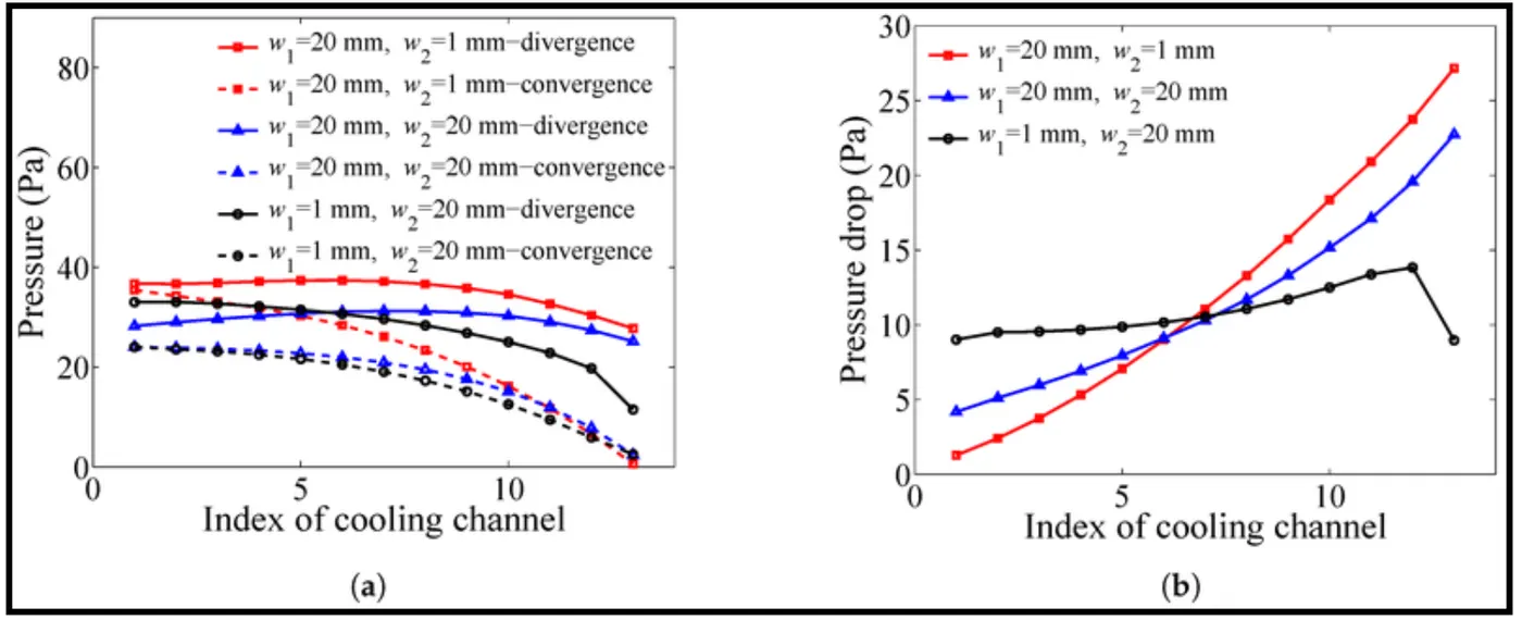
In this section, an optimisation strategy is used to optimise the plenum widths (w1 and w2). First, the value of w2 is fixed, and the value of w1 is optimised. Then, the value of w1 is fixed and the value of w2 is optimised. Take the optimisation of w1 as an example, the detailed steps of the optimisation strategy are shown as follows.
- Set w2 as the fixed value and set the initial range of w1 as [w11,w12]. Calculate the middle point of the range [w11,w12] as w13=(w11+w12)/2.
- Let w1 equal w11, w12 and w13, respectively. Evaluate the values of ΔTmax of these three BTMSs using the CFD calculation, respectively, denoting them as ΔTmax,1, ΔTmax,2 and ΔTmax,3.
If ΔTmax,1<ΔTmax,3,
let w11=w11,w12=w13,w13=(w11+w12)/2, then return to Step 2 and continue the process.
else if ΔTmax,2<ΔTmax,3,
let w11=w13,w12=w12,w13=(w11+w12)/2, then return to Step 2 and continue the process.
else
go to Step 3. - The range for w1 is reduced through using the following strategy. Let w14=(w11+w13)/2 and w15=(w13+w12)/2. Evaluate the values of ΔTmax of the two BTMSs with w1=w14 and w1=w15 using CFD calculation, respectively, denoting them as ΔTmax,4 and ΔTmax,5.
If ΔTmax,4<ΔTmax,3,
let w11=w11,w12=W13,w13=w14,ΔTmax,1=ΔTmax,1,ΔTmax,2=ΔTmax,3,ΔTmax,3=ΔTmax,4.
else if ΔTmax,5<ΔTmax,3,
let w11=w13,w12=w12,w13=w15,ΔTmax,1=ΔTmax,3,ΔTmax,2=ΔTmax,2,ΔTmax,3=ΔTmax,5.
else
let w11=w14,w12=w15,w13=w13,ΔTmax,1=ΔTmax,4,ΔTmax,2=ΔTmax,5,ΔTmax,3=ΔTmax,3. - If (w13−w11) and (w12−w13) are both smaller than a specified threshold, the optimization process is stopped; otherwise, return to Step 3, and continue the process.
Conclude :
- The temperature rise and the temperature difference of the battery pack increase as the discharge rate increases, but the discharge rate cannot be controlled effectively.
- Reducing the inlet air temperature can reduce the absolute temperature of the battery pack, but cannot effectively reduce the temperature rise and the temperature difference of the system.
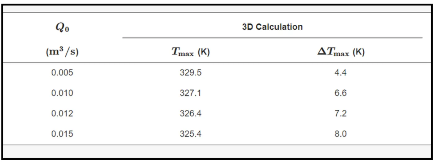
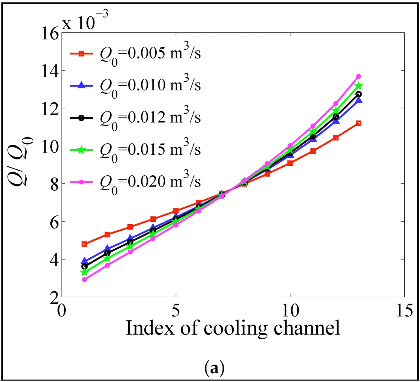
- As the inlet airflow rate increases, the maximum temperature of the battery pack is reduced, but the temperature difference of the battery pack and the power consumption to maintain the flow rate are both increased.
- As the cell spacings decrease, the temperature and the temperature difference of the battery pack are both reduced effectively. However, the decrease of the cell spacing increases the power consumption of the system significantly.
- The angles of the plenums remarkably influence the performance of the BTMS. The maximum temperature and the maximum temperature difference of the battery pack can be reduced effectively through optimising the angles of the plenums, without increasing the total volume and the power consumption of the BTMS.
In summary, in this worst-case scenario with a high ambient temperature, liquid cooling is likely to offer better thermal performance and temperature control for the battery module compared to air cooling. The ability to maintain a lower and more uniform cell temperature is crucial for the safety and longevity of the battery cells. However, it's important to consider the initial cost, complexity, and maintenance requirements of the liquid cooling system when making the final decision.