Project 2
PROJECT 2
1. FROM THE GRILLAGE MODEL FOR THE I GIRDER LONGITUDINAL ANALYSIS OF 4×25M PRESTRESS I GIRDER MODELLED IN PROJECT 1 EXTRACT THE REACTIONS AND ANSWER THE FOLLOWING THE QUESTIONS.
AIM:
- ANALYSIS OF LOADS AND STRESSES ACTING ON PRESTRESSED I GIRDER IN ACCORDANCE WITH IRC 6: 2010
- DESIGN OF THE PRESTRESSED I GIRDER AS PER IRC 18:2000.
- DETEMINATION OF LOSSES AS PER IRC 1343-2000
- TO PREPARE AMODEL OF I GIRDER AND ANALYSE IT IS STAADPRO SOFTWARE .
INTRODUCTION ABOUT I GIRDER
A GIRDER BRIDGE IN GENERAL IS A BRIDGE THAT UTILIZES GIRDERS AS THE MEANS OF CONSISTS OF THREE PARTS THE FOUNDATIONS (ABUTMENT AND PIER) THE SUPERSTRUCTURE (GIRDER TRUSSOR ARCH )AND THE DECK A GIRDER VERY LIKELY THE MOST COMMONLY BUILT AND UTILIZED BRIDGE INN WORLD . IT BASIC DESIGN IN THE MOST SIMPLIFIED FORM CAN BE COMPARED TO SIDE TO OTHER ACROSS A RIVER OR CREEK THE TERM GIRDER IS OFTENUSED INTERCHANGEABLY WITH BEAM IN REFERENCE TO BRIDGE DESIGN.
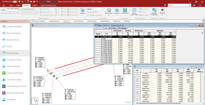
HERE I AM GOING TO EXPLAIN ABOUT THE REACTIONS BY SCREENSHOT:
ON THIS BEAM APPLY DEAD LOAD AND LOAD GENERATION 3 THIS IS MINIMUM VALUE
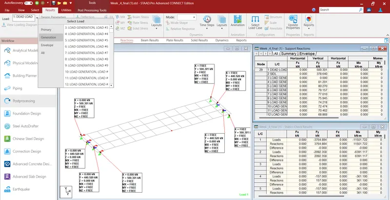
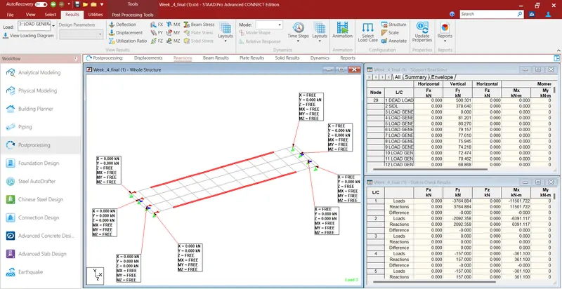
THIS IS MAXIMUM VALUE WHEN LOAD APPLIED LOAD GENERATION 76
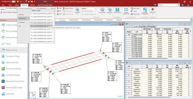
THIS SIDL REACTION
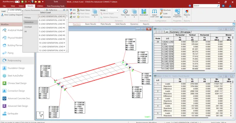
THIS IS THE MINIMUM VALUE OF SIDL LOAD.
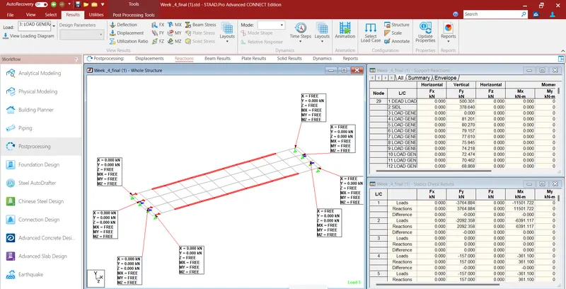
THIS IS MAXIMUM VALUE OF SIDL LOAD
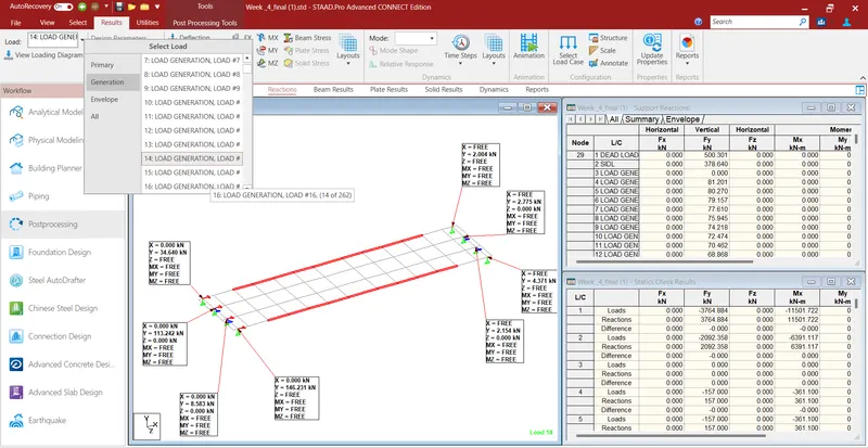
THIS REACTION IS ZERO MAXIMUM AND MINIMUM
2. DESIGN THE ELASTOMERIC BEARING WITH THE GIVEN DESIGN PRAMETERS.
AIM OF ELASTOMERIC BEARING IN BRIDGE
THE PURPOSE OF THE ELASTOMERIC BEARING IS TO SUPPORT A BRIDGE OR OTHER HEAVY STRUCTURE IN A WAY THAT PERMIT THE LOAD TO SHFT SLIGHTLY IN A HORIZONTAL DIRECTION
RELATIVE TO THE GROUND OR FOUNDATION AND REDUCE STRESS INVOLVE.
BANDED ELASTOMERIC BEARING ARE MAINLY USED IN THE STRUCTURE FIELD FOR WHICH THIS PRODUCT HAS MANY ADVANTAGE LONG SERVICE LIFE RELIABLITY MAINTANANCE FREE
LIGHTNESS SMALL OVER DIMENSION AND EASY TO INSTALL.
LIST OF THE DIMENSIONING OF ELASTOMERIC BEARING-
OVERALL WIDTH OF BEARING IN LONGITUDINAL DIRCTION- a = 420 mm
OVERALL LENGTH OF BEARING IN TRANSVERSE DIRECTION- b= 420mm
THICKNESS OF INDUVIDUAL LAYER OF ELASTOMER- ti = 12 mm
THICKNESS OF TOP/ BOTTOM LAYER OF ELASTOMER- te = 6mm
TOTAL NUMBER OF INTERNAL LAYER - n = 5
THICKNESS OF STEEL LAMINATE - ts = 4mm
TOTAL PLAN AREA A= a*b- A = 176400mm squre
EFFECTIVE PLAN AREA A = (a-U)*b - A = 169320.25 mm squre
IN QUESTION ASKING DESIGN OF BEARING AND ALSO IN QUESTION GIVEN DESIGN
PARAMETER AND DESIGN DATA.
DESIGN OF BEARING .
A. MEAN PRESSURE - SERVICEABILITY STATE CLAUSE (4.3.3.1)
σm = P/A ≤ 11 mpa = 3.63 mpa
where
P=Pc+Ps
condition verified
B. NO SLIP - SERVICEABILITY STATE (CLAUSE 4.3.3.2)
B.1 σm mini = P mini /A ≥ 2.0mpa = 3.48 mpa
condition verified
B.2 H<f*P
ENTER THE TYPE OF CONTACT OF BEARING FACE WITH THE STRUCTURE M
M FOR METAL FACE
R FOR RUBBER LAYER
f=0.12+0.2/σm
for slow loads
T>GA Uc/(0.12P+0.2P) => T > 24.55 mm
for a rapid loads;
T> GA(Uc+2Us)/(0.12P+0.2A) => T > 25.36mm
condition verified
C. LIMITATION OF DISTORTION- SERVICEABILITY STATE (CLAUSE4.3.3.3)
th/G≤0.7
or T>(Uc+Us)/0.7 => T > 24.08 mm
condition verified
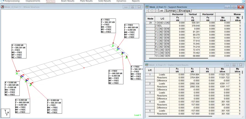
MAXIMUM REACTION ON DEAD LOAD
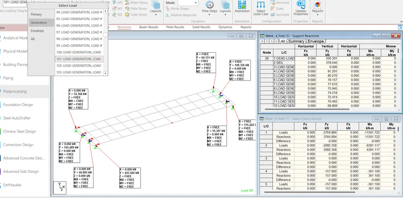
MAXIMUM REACTION ON SIDL LOAD.
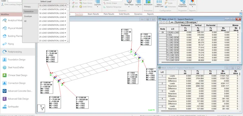
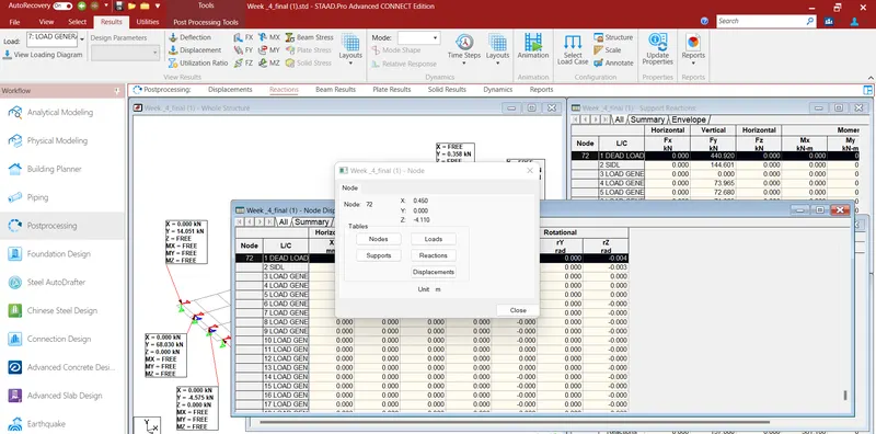
ROTATION OF DEAD LOAD
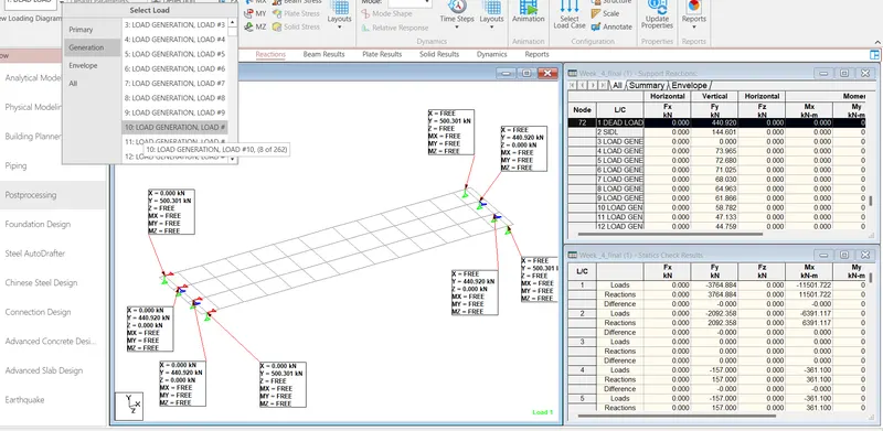
ROTATION OF LIVE AND IMPACT LOAD
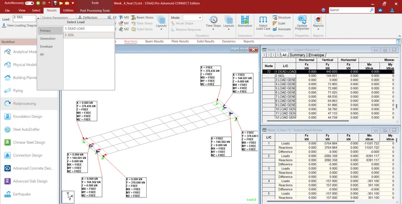
ROTATION OF SIDL LOAD
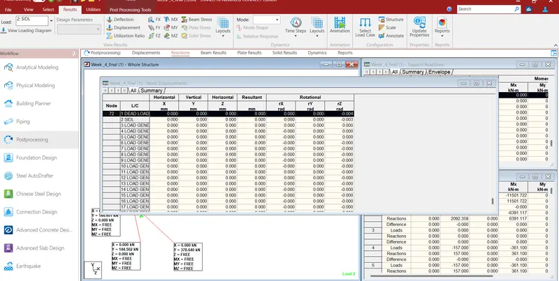
ROTATION OF SIDL LOAD MAXIMUM
3. FROM THE MODEL DETERMINE THE AXIAL LOADS (REACTIONS ) AND MOMENTS IN LONGITUDINAL AND TRANSVERSE DIRECTION AT THE BASE OF THE PIER (DL SIDL LL) USING THOSE VALUE CALCULATE THE DESIGN BM AND DESIGN SF FOR THE DESIGN OF THE OPEN FOUNDATION IN BOTH DERECTION .
AIM:
HERE I AM GOING TO EXPLAIN DETAIL ABOUT OPEN FOUNDATION .
The 'open' refers to the fact that the foundations are made by first excavating all the earth till the bottom of the footing, and then constructing the footing. During the early stages of work, the entire footing is visible to the eye, and is therefore called an open foundation.
- OPEN FOUNDATION IS ALSO KNOWN AS SHALLOW FOUNDATION OR SPREAD FOOTING
- IT IS USED TO GIVE STABILITY TO THE STRUCTURE
- IT TRANSFERS LOADS FROM PIER TO GROUND.
- IT SHOULD BE RIGID ENOUGH TO TRANSFER ALL FORCES TO GROUND.
- THE OPEN REFERS TO THE VERY FACT THAT THE FOUNDATIONS ARE MADE BY FIRST EXCAVATING ALL THE EARTH TILL THE BOTTOM OF THE FOOTING THEN CONSTRUCTING THE FOOTING.
- DURING THE INITIAL STAGES OF WORK THE WHOLE FOOTING IS VISIBLE. AND IS THEREFORE CALLED AN OPEN FOUNDATION.
- THE IDEA IS THAT EVERY FOOTING TAKES THE CONCENTRATED LOAD OF THE COLUMN AND SPREADS IT OVER AN OUTSIZED AREA.SO THAT THE ACTUAL WEIGHT ON THE SOIL DOESNOT EXCEED THE SAFE BEARING CAPACITY OF THE SOIL.
- SUITABLE FOR BRIDGE OF MODERATE HEIGHT TO BE BUILT ON DRY GROUND WHICH IS SUFFICIENTLY FIRM TO SUPPORT THE BRIDGE STRUCTURE.
- BEST SUITED IN SITUATIONS WHERE THE HARD SOIL IS PRESENT WITHIN 1.5TO 3M BELOW THE BED LEVEL OF WATER COURSE AND WHEN THE SCOURING IS MINIMUM.
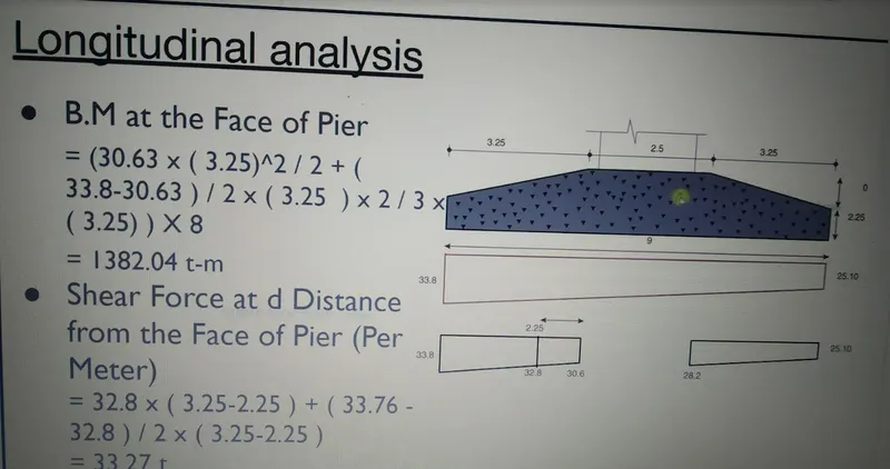
LONGITUDINAL ANALYSIS WITH FIG
B.M AT THE FACE OF PIER.
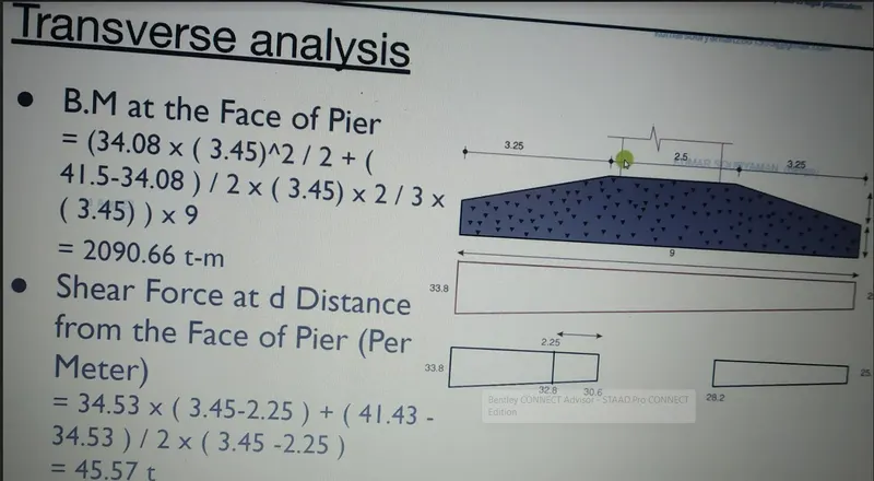
TRANSVERSE ANALYSIS
4. CALCULATE THE LOADS OF THE BASE PIER WIND SEISMIC LWR BRAKING AND CENTIRIFUGAL FORCE WITH THE FOLLOWING DATEA.
Dead load of U- girder Dead load of pier cap
Density of concrete - 2.50 t/m³ volume of pier cap- 31.00
Cross-sectional area of U- girder - 2.173m² Dead load of pier cap- 31*2.5= 77.50 Ton
Dead load of 27m U-girder - 2.173*2.5*27= 146.7 ton
Dead load of pier
Area of pier ( circular pier diameter =1.7m)-2.27
Dead load of pier/m = 2.27*2.5=5.67 Ton
- superimposed dead load
Load due to SIDL - 2.20 Ton/m/track
SIDL of 27 m U- girder- 2.2*27= 59.40 Ton
- LIVE LOAD
- one track one side loaded (longitudinal direction)
- one track both side loaded (longitudinal direction)
- both track one side loaded (longitudinal direction)
4.both track both side loaded(longitudinal direction)
AXLE LOAD
- Braking load:
It is taken as 18 percent of the unfactored vertical loads.
- Traction load:
It is taken as 20 percent of the unfactored vertical loads
- since each track is supported by a single U - girder tractive force of one track and braking force of another track will be taken in athe same direction to produce the worst condition of loading
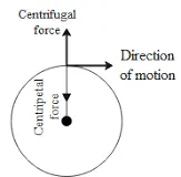
- CENTIRIFUGAL FORCE :
WIND LOAD
calculation of wind load is based on IS - 875(PART3) - 1987.
The design wind at height z is considered as fallow .
Vz= Vb.K1.K2.K3
Vb(m/s) Reginal basic wind speed taken 47 m/s for varanshi
GENERAL PARAMETERS Vb
total structure Height above ground H = 13.6m
Regional basic wind speed Vb = 47m/s
probability factor = 1.07
Terrain Height and structure size factor K2 = 0.856 ASSUMING CATEGORY 3 TERRAIN
TOPOGRAPHY FACTOR K3= 1.0 class c structure
design wind speed at height z, Vz
Vz= Vb. K1. K2.K3= 43.1m/s
wind pressure = 1112.41 N/m²
Pz= 0.6×Vz²= 0.113 t/m²
- LOAD FROM SUPERSTRUCTURE
Over width of both U- girder combined b = 10.15m
contributing length of superstructure l= 27.00m
Total Depth of superstructure d = 1.87m
Height of live load above U- girder h= 3.232m
Transverse wind load without live load = 50.49m
Project area of structure A1 = l×d = 5.73m
PD= Pz×At = 15.62m
Acting @above pier bottom
Transverse wind load with live load
Project area of structure A1= l×d+h = 137.75m
PD= PZ×At = 15.62m
Acting @above pier bottom = 14.80m
Vertical wind load Pv =
Plan Area of superstructure Av= b×l = 274.05m²
Pv= Pz×Av = 31.08t
LOAD ON SUBSTRUCTURE
PIER CAP
Width of pier cap ( conservation)b = 3.10m
length of pier cap d = 9.60m
height of pier cap h = 2.00m
height of pier cap above ground h = 11.55m
wind in longitudinal direction
Ratio a/b=d/b = 0.32
force coefficient Cf = 1.22
projected area of structure At= h×d= 19.20m³
wind force F= Cf×Pz×At= 2.65t
Acting @above pier bottom = 11.05m
wind in transverse direction
Ratio a/b =b/d = 3.10
force coefficient Cf = 1.04
Projected Area structure A1 =h×b = 6.20m³
wind force F = 0.73t
Acting@above pier bottom = 11.05m
PIER
Diametre of pier , b= 1.70m
Height of pier above Ground h = 9.55m
wind in longitudinal /transverse direction
Ratio height /Breadth = h/b = 5.62
force cofficient Cf = 0.80
projected area of structure A1 = h×b = 16.24m²
wind force F = 1.47t
Acting@above pier bottom = 5.28m
SEISMIC ACCELERATION : Ah= (z/2)*(l/R)*(sa/g) where:
Ah= horizontal seismic coefficent to be considered in design
Z= zone factor = 0.16( for varanasi region)
I= importance factor= 1.50
R= response Reduction factor
=4 for pier
sa/g being computed as per irc 6:2017 for medium soil sites
mathematics expressions are:
sa/g=1+15T for 0.0< T <0.10
sa/g=2.5 for 0.10<T<0.55
sa/g = 1.36/T for 0.55<T<4.00
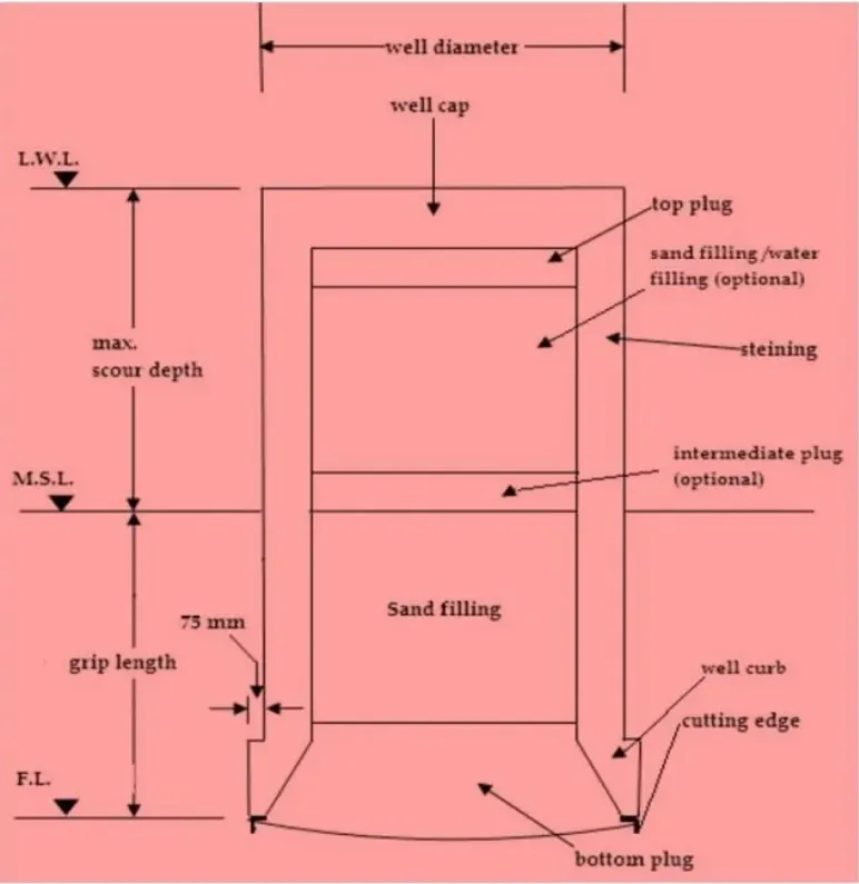
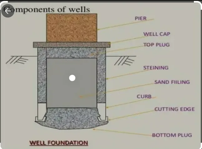
5. WRITE IN DETAIL ABOUT THE COMPONENT OF WELL FOUNDATION AND FUNCTIONS OF EACH COMPONENT WITH RELEVANT DRAWING.
AIM :
- Larger diameters might be extended to larger depths.
- Similar to piles they are shorter.
- If the soil (rock) with a large bearing capability is between 3-7 meters, it may be very effective.
- If the load is not very large, however, the upper 3-7 m soil is not suitable and it may be applied effectively.
- The price of construction is comparatively low on the bed level or lower side.
HERE I AM GOING TO EXPLAIN DETAIL ABOUT THE WELL FOUNDATION AND ITS COMPONENTS.
- Well foundation is a type of deep foundation
- It is provided for structures with foundation beneath rivers or other water bodies.
- It receives the load of the whole structure and transfers it to the ground
- Cassion are used to construct well foundations.
- They are prefabricated hallow box or cylinder.
- They are sunk into ground and filled with concrete.
- 3 type of caissons.
- open caisson
- box caisson
- pneumatic caisson
TYPE OF WELL
- Circular well'
- Rectangular well
- Double rectangular well
- Double octagonal well
- Double -D well '
- Twin Circular well
- Dumb Bell well
- Multiple Dredge Hole well
COMPONENTS OF WELL FOUNDATION.
- Cutting Edge
-
The lowermost portion of the well curb is leading edge.
It is operate to cut the soil throughout the sinking.
- Well Crub
- This transfers loads to ground through cutting edge while sinking;
- material are Timber and rcc
- Bottom plug
-
After the well is sunk to the required depth, the bottom of the well is plugged with concrete known as a bottom plug.
It is operated to transmit the load to the subsoil.
- Steining
- brick/stone masonary PCC or RCC materials are used .
- The design relies on the unit weight of well and skin friction
- Top plug
- The top plug is an unreinforced concrete plug, generally provided with a thickness of about 600 mm beneath the well cap to transmit the loads from the pier to the steining. Minimum grade of concrete used in top plug is M15.
- Well cap
- It is constructed as a slab resting on the well.
- It transfers load of the pier to the well;
- This acts as an interim layer between the pier and well foundation to accommodatte pier.
- It is designed such that the pierr base is provided with a minimum all round offset.
- The centre of the cap coinncides witth the pier instead of the well to nulify th effects of shifts occurred during well sinking.