Challenge 3
Challenge 3
AIM;
Staad pro provides flexible modelling environment flunent data collaboration and advance feature. It best structure analysis and design software that support Indian as well as International codes. Staad pro permit structure engineer design and analysis any type of structure virtually.
- What are the sectional properties we need upfront for designing a metro viaduct? What is the supporting software for identifying the sectional properties and designing them?
slution- when we designing the metro viaduct the section properties is needed.
AREA- metre square
PERIMETR- metre
BOUNDING BOX- X
Y
CENTROID- X
Y
MOMENT OF INERTIA- X
Y
What is the supporting software for identifying the sectional properties and designing them?
- By using the software when desiging the sectional properties of metro viaduct is.
1) lenght
breadth
slpoe
flenze height
we calculate by using the staad pro software
And by using the software provide for
1) rectangular section
2) holo section
2.Explain the detailed steps involved how elements are created in STAAD Pro and how are the inputs for sectional properties assigned?
ans- In staad pro involve basic element like node plate etc.
I am trying to explain with screenshot.of element are created in STAAD pro.
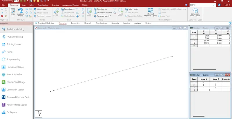
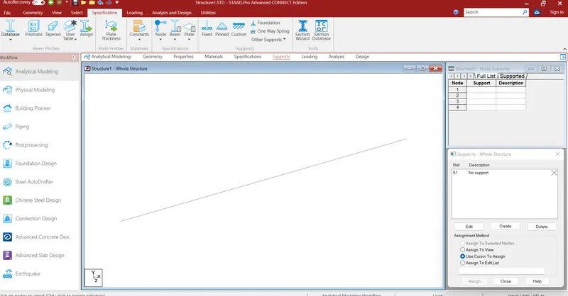
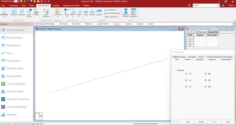
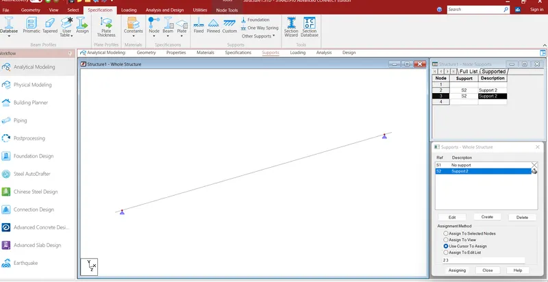
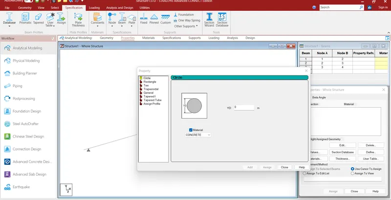
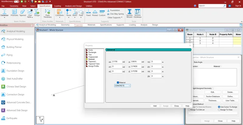
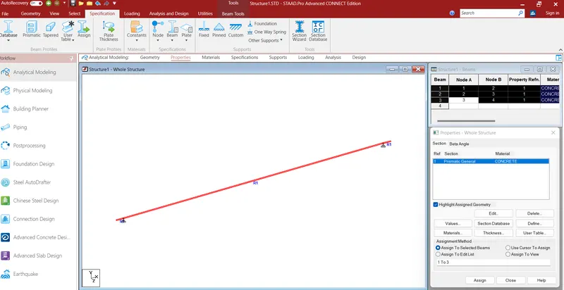
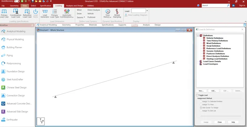
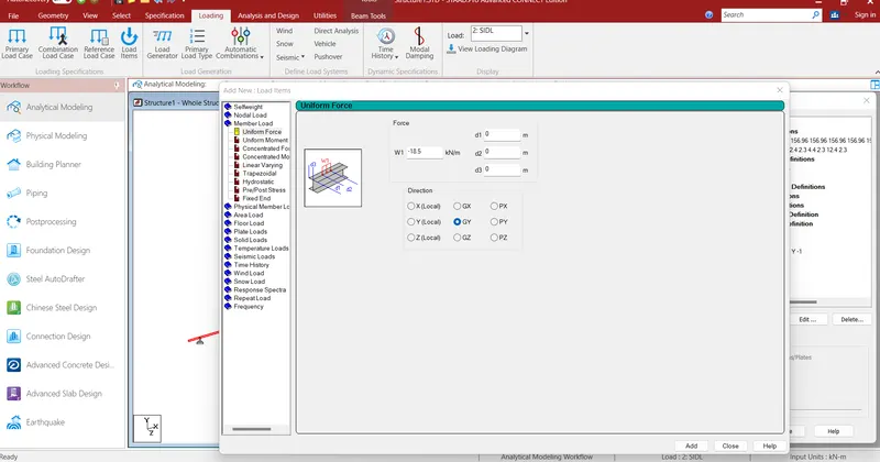
result - in this software all element shown in fig step wise .
3.What are SLS combinations used for live loads, with respect to impact factor and how the moments for the section are derived?
ans- Structural loads can be broadly classified into four groups: dead loads, live loads, impact loads, and environmental loads.
what is live load.
- Live loads- are moveable or temporarily attached to a structure when passed vehicle on bridge there produce live load
-impact load- Impact loads are sudden or rapid loads applied on a structure over a relatively short period of time compared with other structural loads. They cause larger stresses in structural members than those produced by gradually applied loads of the same magnitude. Examples of impact loads are loads from moving vehicles, vibrating machinery, or droppe weights. In practice, impact loads are considered equal to imposed loads that are incremented by some percentage, called the impact factor.
DEAD LOAD- Dead loads are structural loads of a constant magnitude over time. They include the self-weight of structural members, such as walls, plasters, ceilings, floors, beams, columns, and roofs. Dead loads also include the loads of fixtures that are permanently attached to the structure
Now question is asking about load combination of SLS( STRUCTURAL LOAD SYSTEM)
SLOUTION-
| BEAM 2 | L\C 1DL 2 SIDL 134 LOAD G |
Max+ve Max-ve Max+ve Max-ve Max+ve Max+ve Max-ve |
DIST METRE 25.6 12.8 25.6 12.8 0.00 10.667 | MZ KN-M 11.667 -4183.550 5.012 -1797.228 0.000 -2969 | DIST M 0.00 0.00 0.00 0.00 0.00 | MY KN-M 0.00 0.00 0.00 0.00 0.00 |
SLS load combination= DL+1.2*SIDL+1.1*LL*1
where
I impact = 1+[0.15+(8\(6+L))]= l+[0.15+(8\(6+25.6)*(90/116)=1.313
moment M- ( 4183.55+ 1.2*1797.228+1.1*2969.161*1.313 KN-M
= 10628.58 KN-M
3.What is prestressing in girders? What are advantages of Prestressed girders in a metro project.
ANS- Prestressed girder are type of concrete girder that facilities the rapid construction of bridge using girder fabricated off-site and then transported and erected into place at job site.
method of prestressing-
In prestressing concrete structure prestress is introduced by stretching steel wire and anchoring them aganist concrete. Therefore the prestressing system should comprise and essentially a method of stretching the steel and a method of anchoring it to the concrete.
ADVANTAGE OF PRESTRESS GIRDER IN METRO PROJECT
- The inherent compressive strength of concrete is used to its fullest.
- The special alloy steels used to form the prestressing tendons are used to their fullest.
- Tension cracks are eliminated, reducing the risk of the steel components corroding.
- Shear stresses are reduced.
Precast construction enabled us to get a better-quality control by casting in a factory-like set-up of a casting yard. Cast-in situ construction of heavy structures like U-girders, pier cross arms and other station elements would have required extensive labour and temporary structures for support from the ground and about 20m wide construction space of narrow and busy roads. The precast construction method reduced the working space to just half of it and that too a available spaces in any other location. Such gains were essentially required for the proposed metro alignment which is characterized by sharp curvatures in crowded areas of the city.
5.Explain about prestressing losses? What are different type of prestressing losses and mention the significance of the prestressing losses?
- Early attempts to produces prestressed concrete was not successful due to loss of prestress transferred to concrete after few years.
- prestress loss is nothing but the reduction of initial applied prestress to an effective value.
- In other word ,loss in prestress is the difference between initial prestress and in effective prestress that remains in a member
- Loss of prestress is great concern since it affect the strength of member and also siginificantly affects the members serviceability including stress in concrete cracking camber and deflection.
THERE ARE TWO TYPES OF PRESTRESSING LOSSES
1. Immediate losses include
- Elastic shortening of concrete
- Slip at anchorage immediately after prestressing and
- Friction between tendon and tendon duct and wobble Effect
2. Time Dependent losses include
- Creep and Shrinkage of concrete and
- Relaxation of prestress steel
MENTION THE SIGNIFICANCE OF THE PRESTRESSING LOSSES.
TYPE OF LOSS PRE-TENSIONING POST- TENSIONING
1. Elastic shortening Yes i No, if all the cables are simultaneously tensioned.
ii If the wire are tensioned in stage loss wil Exist.
2.Anchorage slip No yes
3.Friction loss No yes
4.Creep and Shrinkage of concrete Yes yes
5.Relaxation of steel Yes Yes
6.How a girder is being prestressed while fabrication? Explain the components/materials used during the prestressing?
Ans-When girder can fabricated using five step
- Is to weld studs to the steel beam pretension strands place reinforcements and install formwork.
2.Is to place concrete into the formwork and finish the top surface of concrete.
3.The steel beam is placed on top of the fresh concrete and is supported by the chairs and the studs at bottom penetrate into the fresh concrete.
4.Is to strip the formwork and release and cut the strands.
5.Is to install formwork and reinforcement and placed concrete for the RC deck and step 2 and 3 can be switched if the width of bottom flange allows casting the concrete while the steel girder is in place.
MATERIAL USED DURING CONSTRUCTION IS.
1 Steel
ordinary mild steel and deformed bars used in R.C.C. are not used in PSC (Prestressed concrete) because their yield strength is not very high. In the PSC, loss of prestress (about 20%) occurs due to many factors. If mild steel or HYSD bars are used then very little prestress will be left after the losses and will be of no use for us. Therefore, high tensile strength steel is used for prestressing. In addition to the high strength, the steel used in prestresing must have a higher ultimate elongation. Various forms of steel used for prestressing are as follows:
2 tendon wire
Tendons are high strength tensile wires available in various diameter from 1.5mm to 8mm. Table gives the ultimate tensile strength of steel wires used for prestressing.
3 bar
High tensile steel bars of diameter 10mm or more are also used in prestressed concrete.
4 concrete
Since high tensile steel is used in PSC, the concrete used should also be of good quality and high strength. Therefore, IS code recommends a minimum mix of M40 for pretensioned system and M30 for post tensioned system. These mixes have high strength and a high value of modulus of elasticity of concrete which results in less deflection.
7.How are stresses in the girder calculated with the resultant prestressing losses?
Prestressing losses in girder.calculated
ans - Elastic shortening fy=mfc
where fy= drop in prestress
m= modular ratio
fc= stress in concrete
In a girder creep loss and shrinkage loss anchorage loss etc.
creep loss = fp=Ep ecr, ult
shrinkage loss=Fp=Ep esh
where
fp= loss in prestress
Ep= modulos of prestressing steel
Ecr,ult= ultimate creep strain
Esh=ultimate shrinkage strain
no of strands used (n)= 72
prestressing force applied=p
0.765fpu*As*n*(1-loss)/1000 kn
=(1422.9*140*72*82.5%)/1000kn= 11832.8 kn
sectional modulus(Z)=I/Y
for cheaking stress at bottom
Ybot=0.594m
Z=(0.74035/0.594 metre cube=1.2464
stress at bottom= p/a+P*e/z-m/z
(11832.8/2.1735)+11832.8*0.494/1.2464)-10628.58/1.2464)
= 544.12+4689.83-8527.42 kn/metre square= 1.607 N/mm square
8. Explain the step wise procedure of transverse analysis of open web structure of U girders in STAAD pro along with how the vehicle parameters and loadings are fed in the STAAD software.
SOLUTION- THIS PROCEDURE IS DOING BY STAAD SOFTWARE
STEP1- NODE VALUE PUT.
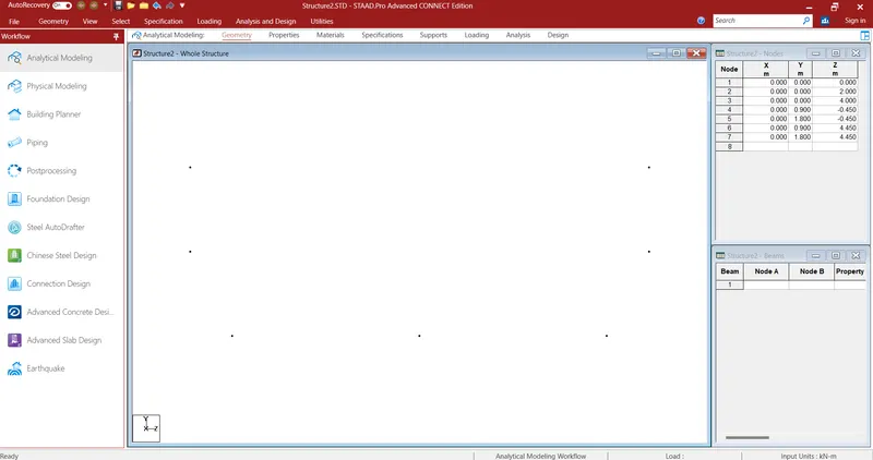
STEP 2 AFTER PUTING NODE VALUE
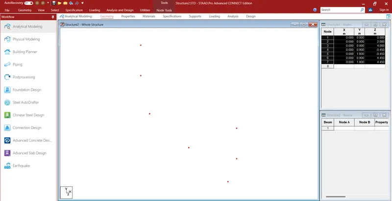
STEP 3 GO TO GEOMETRY
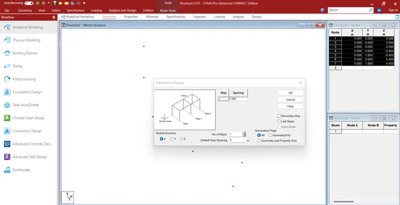
STEP 4 IN STEP SET THE SAPACING OF NODE
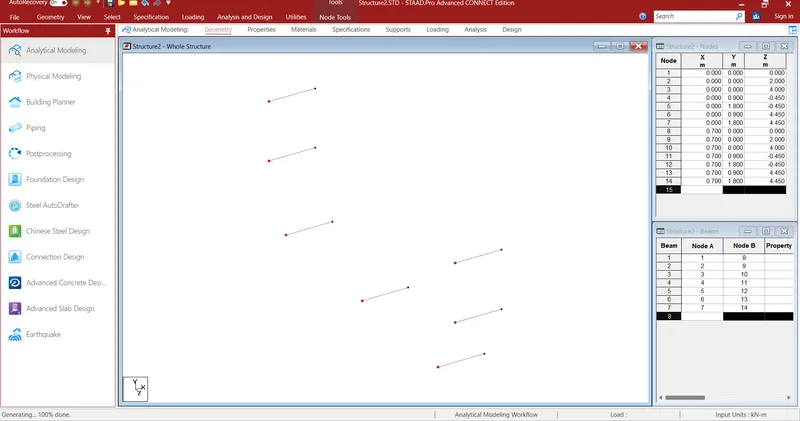
STEP5 CONNECT THE NODE TOGETHER
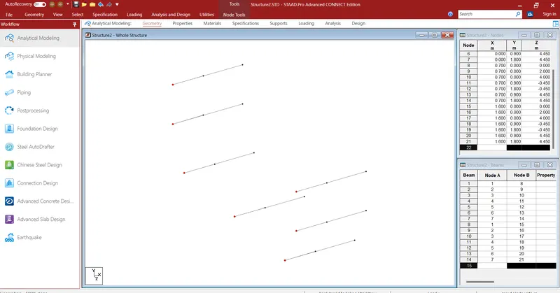
STEP 6 CLICK ON ISOMETRIC VIEW
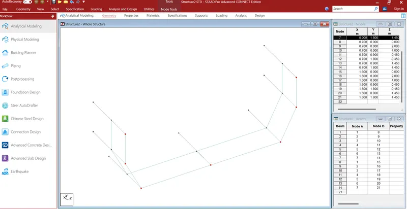
STEP 7 GO TO PLATE CURSIER
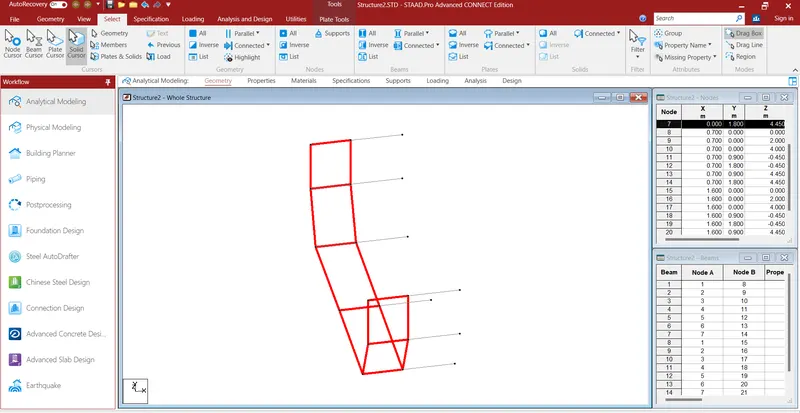
STEP 8 ALL NODE CONNECT AFTER THIS VIEW
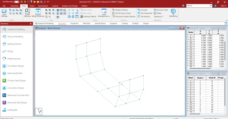
STEP 9 GO TO TOP VIEW
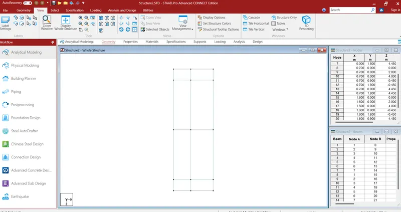
STEP 10 SLECT PLATE CURSIER
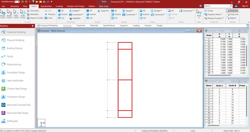
STEP 11 GO GEOMETRY
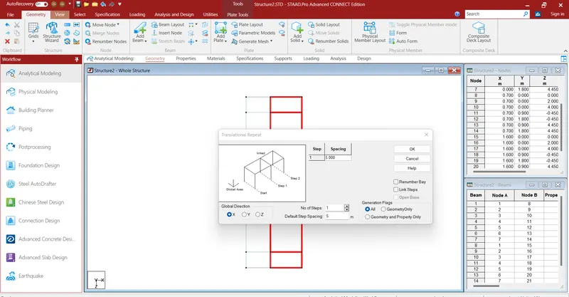
STEP12 THIS VIEW IS TOP
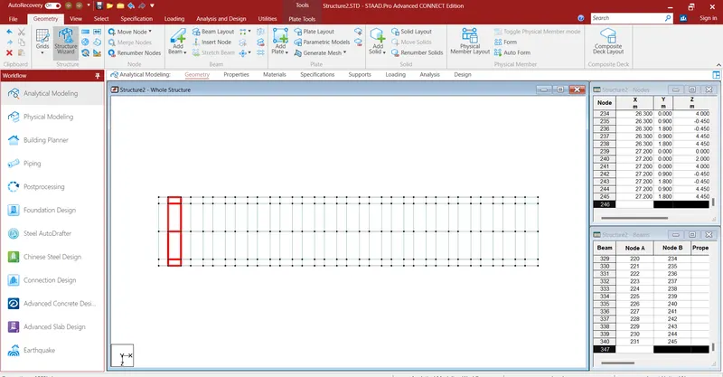
STEP 13
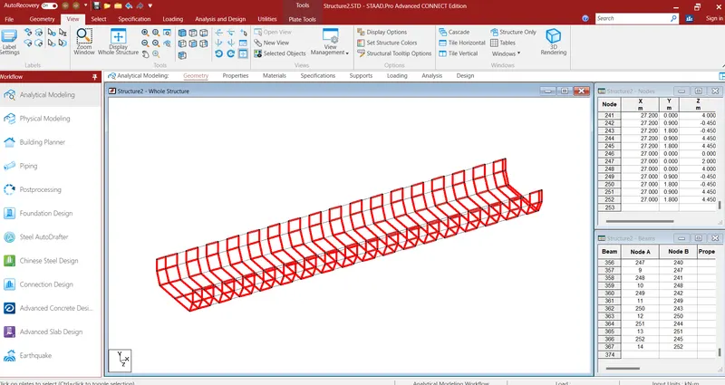
STEP 14 MAKE BEAM
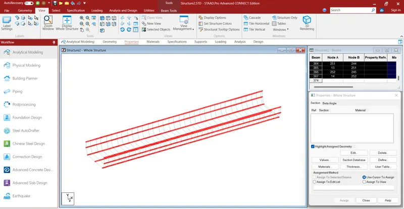
STEP 15 CHEAK THICKNESS
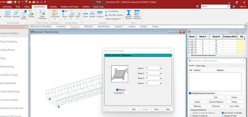
STEP 16 AFTER THE PUTING THIKNESS CLICK ISOMETRIC VIEW
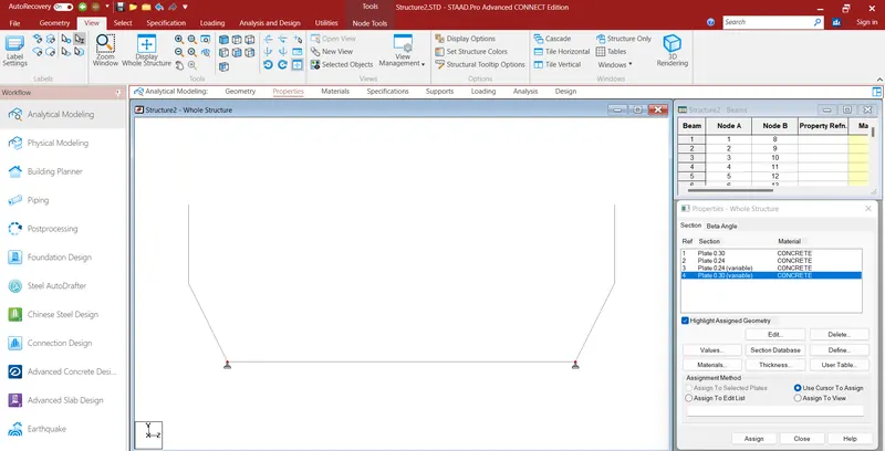
STEP 17 ASSIGN THE PLATE
17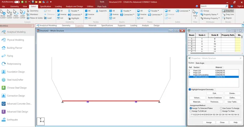
STEP 18
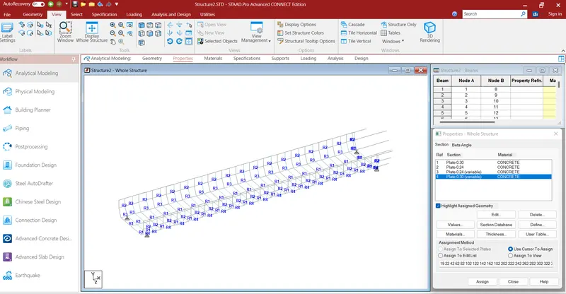
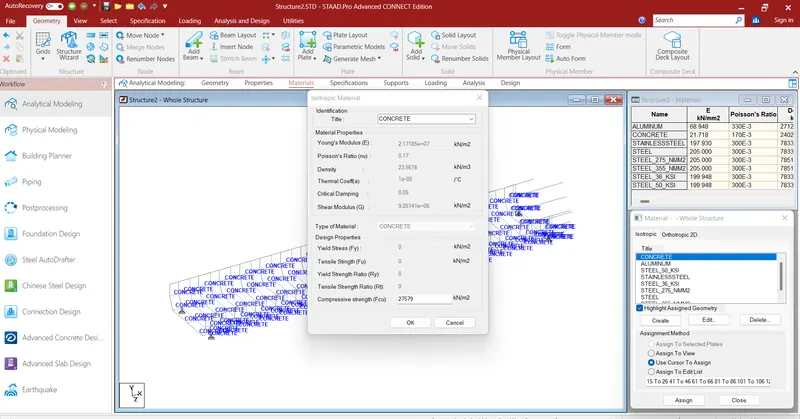
STEP 19 ASSIGN THE CONCTRETE
STEP20 LOADING VIEW
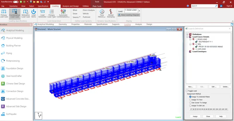
STEP 21 LOADING PART POINT
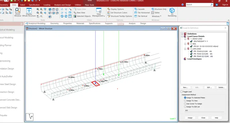
NOW ANSWER IS OVER.I FALLOW ALL STEP THAT IS AVAILVAL IN LECTURE .
9.How is the longitudinal analysis of open web structure of U girder performed, final design bending moments and axial stresses are extracted? Explain the software procedure for extracting the same.
ANS - SOLUTION BY SCREENSHOT
STEP 1 PUT NODE
STEP 2 GO SUPPORTS AND CLICK PINNED
STEP3 CREATE SUPPORT AND ASSIGN TO SELECTED NODE
STEP 4 GO PROPERTY AND CLICK ON RECTANGLE
STEP5 PUT THE VALE OF COORDINATE
STEP 6 THIS IS BEAM SECTION CREATE
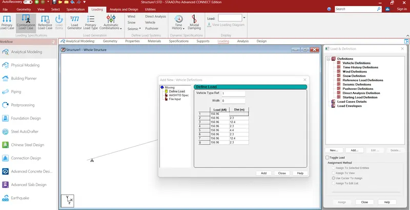
STEP 7 GO TO LOAD AND SELECT VECHICLE
STEP8 DEFINE LOAD AND PUT VALUE
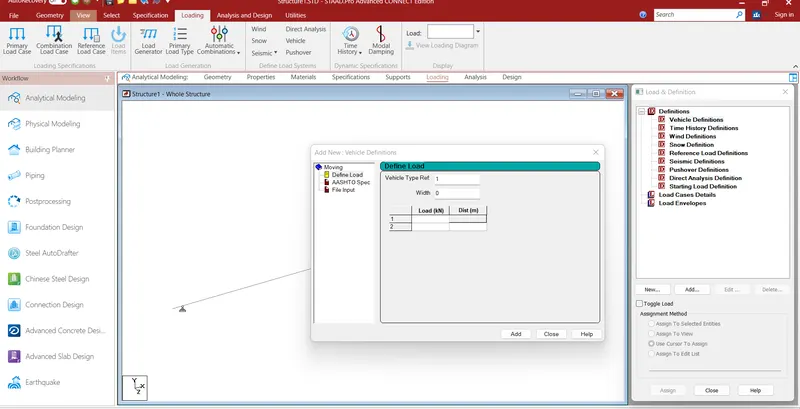
STEP 9 ALL VALUE PUT
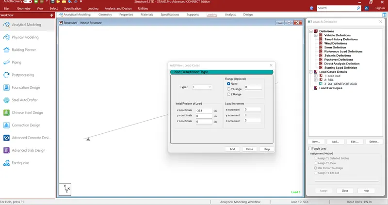
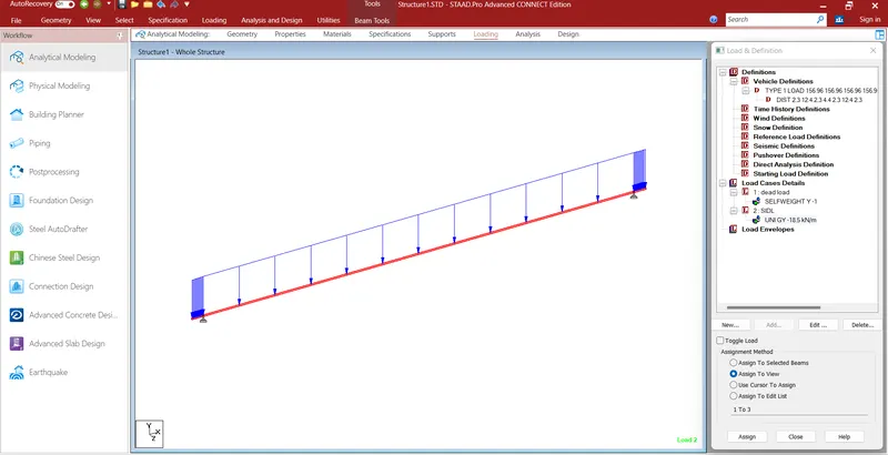
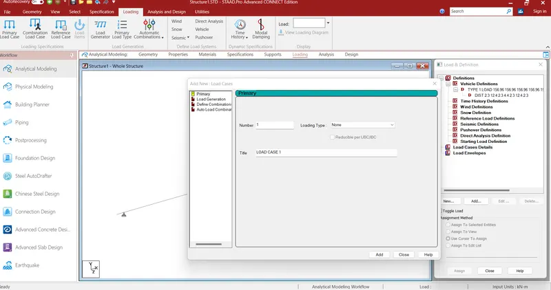
STEP 10 ALL DEAD LOAD LIVE LOAD AND SIDL LOAD ON VECHICLE
STEP 11 LOAD VALUE ON BEAM SHOWN
STEP12 BEAM LOAD SHOWN
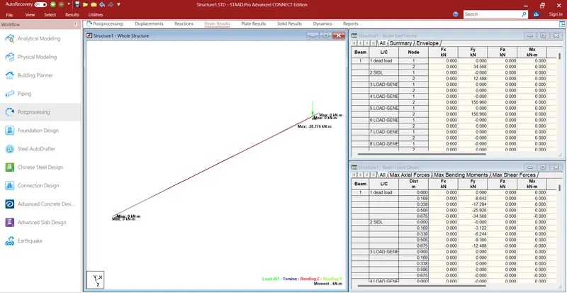
STEP 13 AXIL LOAD
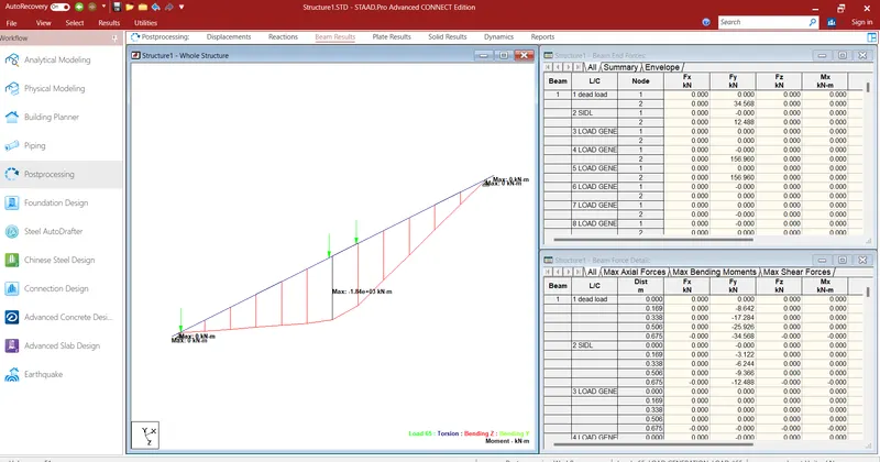
STEP 14 BEAM RESULT
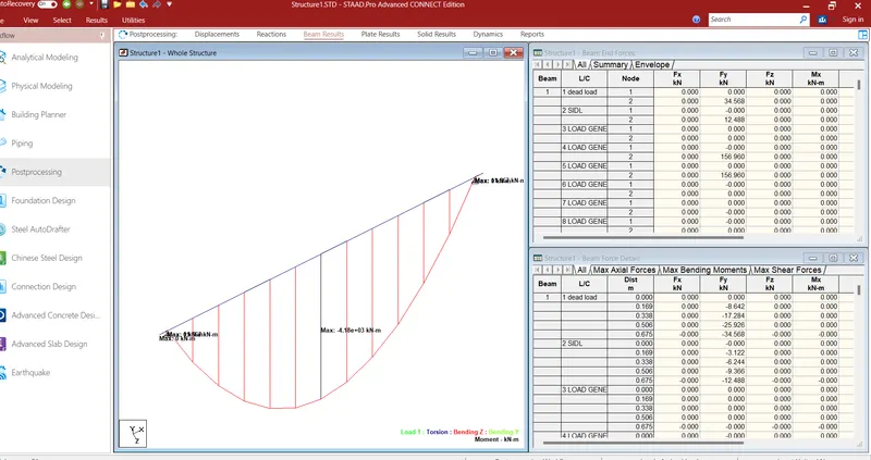
STEP 15 SIDL LOAD IS SHOWN
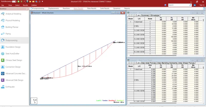
NOW THE ALL SOLUTION IS ON FIG .