Challenge 1
- Why is a metro rail needed in countries with developing economy? What is your basic understanding on the differences between a conventional rail system and a metro rail system?
ADVANTAGE OF METRO
- The Metro Rail System has proven to be most efficient in terms of energy consumption, space occupancy and numbers transported.
- High-capacity carriers – very high volumes of peak hour peak direction trips.
- Eco-friendly – causes no air pollution, much less sound pollution.
- Low energy consumption – 20% per passenger km in comparison to road-based systems.
- Greater traffic capacity – carries as much traffic as 7 lanes of bus traffic or 24 lanes of car traffic (either way).
- Very low ground space occupation – 2 meter width only for elevated rail.
- Faster – reduces journey time by 50% to 75%.
CONVENTIONAL RAIL SYSTEM
The conventional rail system is a system designed for the speed of up to 200km/h and that network consists of: lines intended for the transport of passengers, lines intended for the freight transport and lines intended for combined transport (transport of passengers and goods), railway junctions .
The conventional rail system in India has a total route length of almost 68,000 km, shared by passenger and freight transport. Metro systems exist in 10 Indian cities, with about 515 km of track in operation and an additional 620 km of metro rail under construction. A further 600 km of metro lines are planned in the upcoming years.
Significant investments have been made in high-speed rail and metros rather than in conventional rail. High-speed rail provides an important alternative to aviation, while urban rail provides a solution to cities impacted by congestion and air pollution. Rail passenger traffic in India has increased by almost 200 per cent since 2000 and freight traffic by 150 per cent, yet latent demand for mobility in India remains huge. For example, on average, each Indian travels about three kilometres per day by privately owned road vehicle, compared to 17.5 km in Europe.
It shows that higher investments in electrifying railway networks could significantly reduce polluting carbon dioxide emissions from transport while providing access to efficient and sustainable transport for all. Expanding rail transport in growing urban centres would also increase reliability, reduce congestion and noise pollution, and improve local air quality. “The rail sector can provide substantial benefits for the energy sector as well as for the environment. By diversifying energy sources and providing more efficient mobility, rail can lower transport energy use and reduce COs and local pollutant emissions,” said IEA executive director, Dr Fatih Birol.
The report has also revealed that the rail network is set to grow more in India than in any other country, with passenger movement in India reaching 40 per cent of global activity. Activity in India is already among the highest in the world, being second only to China for passenger movement and fourth for freight movement. Rail passengers in India travel 1.2 trillion km, more than the distance travelled by cars.
METRO RAIL SYSTEM
- The Metro Rail System has proven to be most efficient in terms of energy consumption, space occupancy and numbers transported.
- High-capacity carriers – very high volumes of peak hour peak direction trips.
- Eco-friendly – causes no air pollution, much less sound pollution.
- Low energy consumption – 20% per passenger km in comparison to road-based systems.
- Greater traffic capacity – carries as much traffic as 7 lanes of bus traffic or 24 lanes of car traffic (either way).
- Very low ground space occupation – 2 meter width only for elevated rail.
- Faster – reduces journey time by 50% to 75%.
METRO UNDER THE CONSTRUCTION
SYSTEM CITY STATE
NAVI MUMBAI METRO NAVI MUMBAI MAHARASHTRA
PUNE METRO PUNE MAHARASHTRA
KANPUR METRO KANPUR UTTARA PRADESH
BHOJ METRO BHOPAL MADHYA PRADESH
INDORE METRO INDORE MADHYA PRADESH
AGRA METRO ARA UTTAR PRADESH
PATNA METRO PATNA BIHAR
PROPOSED METRO
THANE METRO THANE MAHARASTRA
COIMBATORE METRO COIMBATORE TAMIL NADU
GREATER GAWALIOR METRO GWALIOR MADHYA PRADESH
JABALPUR METRO JABALPUR MADHYA PRADESH
BAREILLY METRO BAREILLY UTTAR PRADESH
PRAYAGRAJ METRO PRAYAGRAJ UTTAR PRADESH
RANCHI METRO RANCHI JHARKHAND
FUTURE PLANS OF METRO
DEHRADUN METRO DEHRADUN UTTARAKHAND
KOZHIKODE LIGHT METRO CALICUT KERALA
THIRUVANANTHAPURAM LIGHT METRO THIRUVANANTHAPURAM KERALA
SURAT METRO SURAT GUJARAT
SRINAGAR METRO SRINAGAR JAMMU AND KASHMIR
JAMMU METRO JAMMU JAMMU AND KASHMIR
MEERUT METRO MEERUT UTTAR PRADESH
GUWAHATI METRO GUWAHATI ASSAM
GORAKHPUR METRO GORKHPUR UTTARPRADESH
VISAKHAPATNAM METRO VISAKHAPATNAM ANDHRA PRADESH
VIJAYAWADA METRO VIJYAWADA ANDHRA PRADESH
OPERATIONAL METRO INDIA
KOLKATA METRO KOLKATA WEST BENGAL
DELHI METRO DELHI DELHI HARYANA UP
NAMMA METRO BENGULURU KARNATAKA
RAPID METRO GURGAON GURUGRAM HARYANA
MUMBAI METRO MUMBAI MAHARASHTRA
JAIPUR METRO JAIPUR RAJASTHAN
CHENNAI METRO CHENNAI TAMIL NADU
KOCHI METRO KOCHI KERALA
LUCKNOW METRO LUCKNOW UTTAR PRADESH
HYDERABAD METRO HYDERABAD TELANGANA
NOIDA METRO NOIDA DELHI
AHMEDABAD METRO AHMEDABAD GUJARAT
NAGPUR METRO NAGPUR MAHARASHTRA
3.Why DMRC is the busiest metro in India. Apart from the points mentioned in the course video. You can find several interesting facts on the internet. Please research and provide your learnings.
DMRC is the busiest metro becouse
1 population is more in delhi city
2 All head office of the india
3 more malls and small office in delhi
4 many colleges like engineering and school
5 many VIP hospital like AIIMS, MEDANTA ETC
6 Many factories is availaval in delhi so empolyment is not reach time because traffice is more so use metro and reach to time
7 this economy for travalling
8 more government and private sector empolyment .
so this is busiest in india delhi metro
4.What are the components of a Metro rail? Explain briefly about the concepts of the components?
- FOTS ( Fiber Optic Transmission System)
- PIDS (Public Information Display System)
- PAS (Public Address System)
- Master Clock.
- CCTV (Closed Circuit Television)
- Radio System.
- EPABX (Electronic Private Automatic Branch Exchange)
I preferred elevated metro because Apart from the lower cost of construction, elevated lines require less electricity for cooling and lighting. Cities across the world have a preference for elevated MRTs.
Elevated metro is cheaper than underground anyday. There are cable ducts/sewage lines/building foundations underground that are hard to get around, also the curves can only be so tight with the underground construction. Once built, the expansion, such as, adding a third line/making platforms longer/any other miscellaneous construction is very hard. All the metro constructions in india are new and hence have to use boring machine, whereas most, if not all, constructions in developed countries were ‘cut and cover’ which requires you to
a. dig the section
b. build the tunnel
c. cover it back up
This was possible back then (50–100 years ago) since there were not a lot of buildings/structures around, and was also cheaper/easier compared to elevated subways.
disadvantage of underground metro
- They are really really expensive to build. Tunneling is expensive. If you`re in a rocky environment, they`re impractical
- Getting people to track level poses some serious accessibility issues. It`s not just people in wheelchairs - some of the older systems like New York`s often have stations with over a hundred stairs from street to track level and that means the elderly have to avoid them too.
- In low lying places, flooding is an issue. Hurricane Sandy flooded large parts of New York`s system. When the Seine rises, the Paris Metropolitan has to go on high alert because it`s located well below the level of the river. In areas with muddy soil, they might not be practical (although Amsterdam has a short underground metro)
- Evacuation can be a problem. There was a horrendous fire in the London Underground over 30 years ago that led them to replace all their wooden escalators with metal ones. In a situation like that (and electrical fires do happen) you can easily have a lot of people trapped in a confined space with no escape.
Following cities in India having underground metros are-
- Kolkata Metro
- Delhi Metro
- Chennai Metro
- Bengaluru Metro
ast, earth-shattering expense.
No breathing air underground.
The difficulty of getting emergency equipment to people who are stranded underground by accident or medical emergency.
Drainage issues.
High reliance on (expensive) artificial light instead of (free) sunlight.
Total lack of landmarks to tell us where we are.
Earthquake.
Suicide rates would probably rise.
You cannot land military airplanes in tunnels. You can land them on interstate highways.
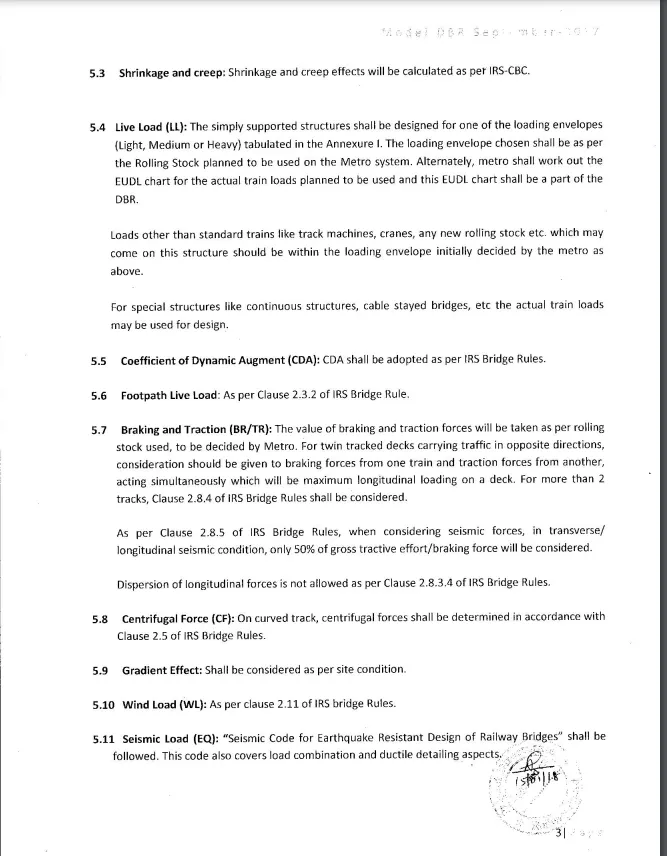
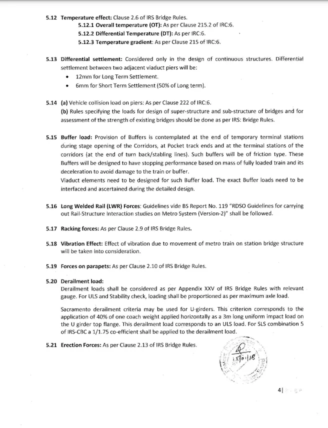
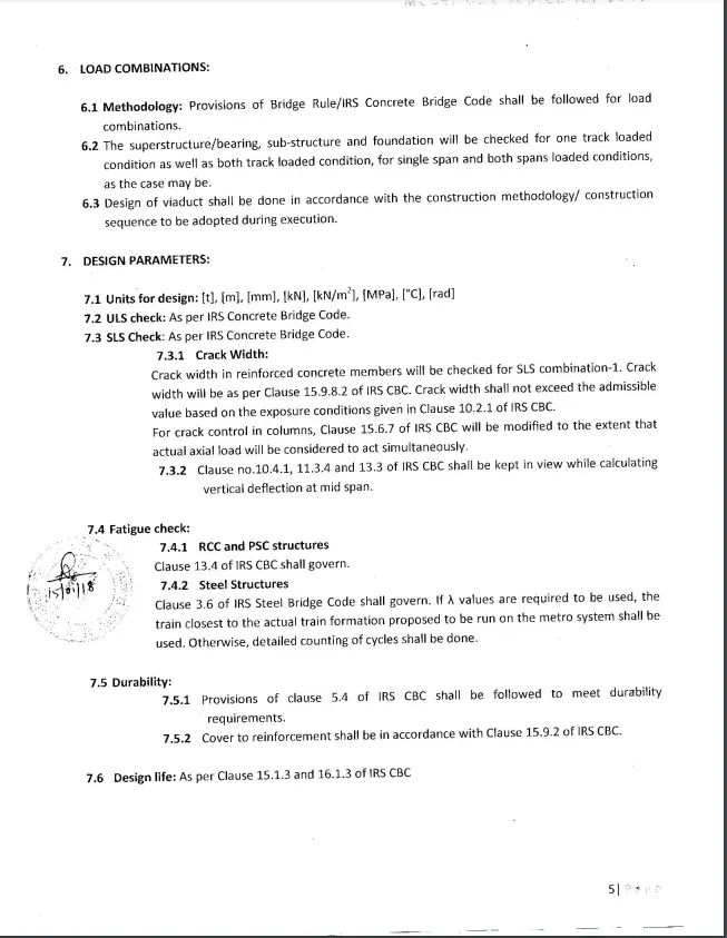
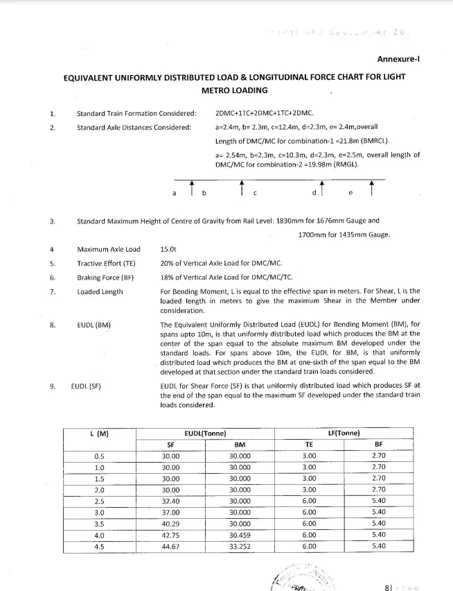
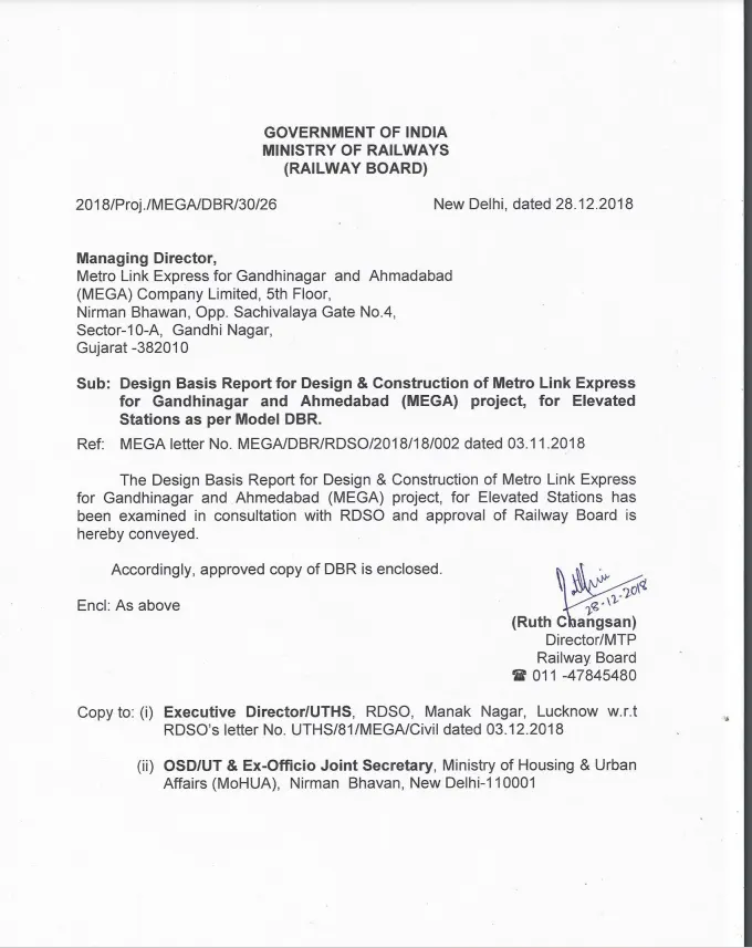
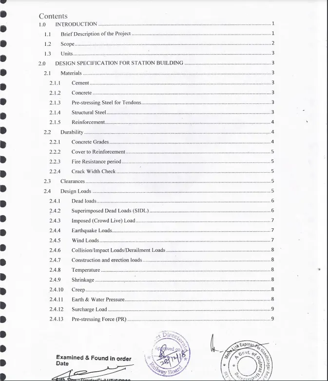
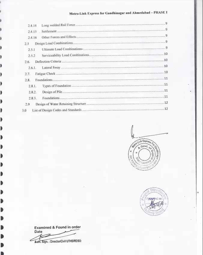
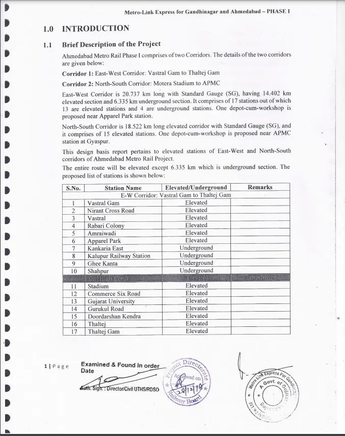
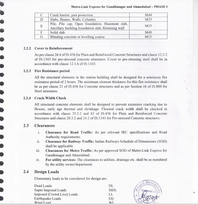
6.What is a Design Basis Report (DBR)? In which phase of a project a DBR is prepared?
Basis of Design Report or “DBR” shall mean a planning report that documents the major design criteria and includes recommended project elements, planning level drawings, preliminary schedules, and cost estimates.
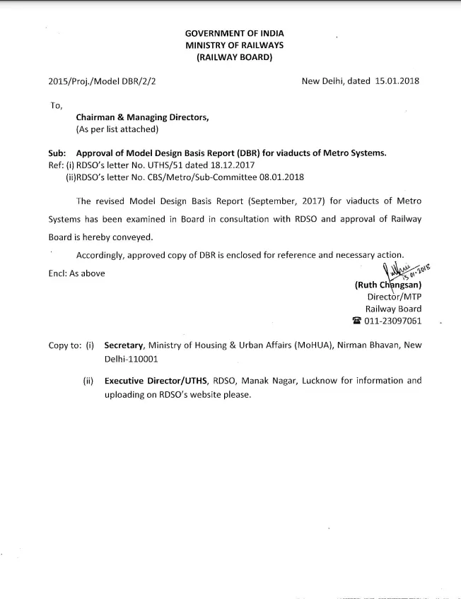
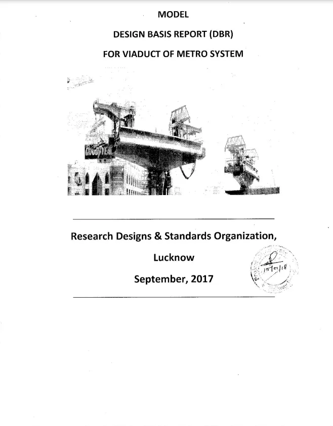
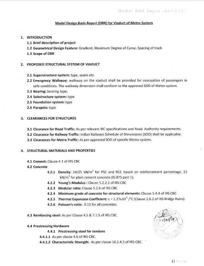
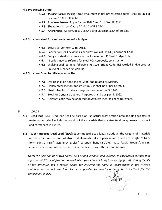


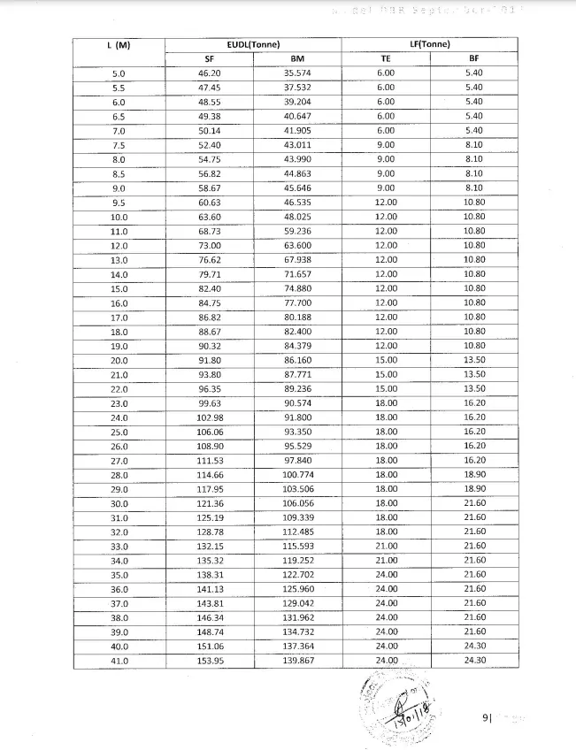
- What is significance of a DBR of an elevated metro?
9.In the planning of metro project, what are the chronology of activities before the construction?
9. Construction Planning
9.1 Basic Concepts in the Development of Construction Plans
Construction planning is a fundamental and challenging activity in the management and execution of construction projects. It involves the choice of technology, the definition of work tasks, the estimation of the required resources and durations for individual tasks, and the identification of any interactions among the different work tasks. A good construction plan is the basis for developing the budget and the schedule for work. Developing the construction plan is a critical task in the management of construction, even if the plan is not written or otherwise formally recorded. In addition to these technical aspects of construction planning, it may also be necessary to make organizational decisions about the relationships between project participants and even which organizations to include in a project. For example, the extent to which sub-contractors will be used on a project is often determined during construction planning.
Forming a construction plan is a highly challenging task. As Sherlock Holmes noted:
Most people, if you describe a train of events to them, will tell you what the result would be. They can put those events together in their minds, and argue from them that something will come to pass. There are few people, however, who, if you told them a result, would be able to evolve from their own inner consciousness what the steps were which led up to that result. This power is what I mean when I talk of reasoning backward.
Like a detective, a planner begins with a result (i.e. a facility design) and must synthesize the steps required to yield this result. Essential aspects of construction planning include the generation of required activities, analysis of the implications of these activities, and choice among the various alternative means of performing activities. In contrast to a detective discovering a single train of events, however, construction planners also face the normative problem of choosing the best among numerous alternative plans. Moreover, a detective is faced with an observable result, whereas a planner must imagine the final facility as described in the plans and specifications.
In developing a construction plan, it is common to adopt a primary emphasis on either cost control or on schedule control as illustrated in . Some projects are primarily divided into expense categories with associated costs. In these cases, construction planning is cost or expense oriented. Within the categories of expenditure, a distinction is made between costs incurred directly in the performance of an activity and indirectly for the accomplishment of the project. For example, borrowing expenses for project financing and overhead items are commonly treated as indirect costs. For other projects, scheduling of work activities over time is critical and is emphasized in the planning process. In this case, the planner insures that the proper precedences among activities are maintained and that efficient scheduling of the available resources prevails. Traditional scheduling procedures emphasize the maintenance of task precedences (resulting in critical path scheduling procedures) or efficient use of resources over time (resulting in job shop scheduling procedures). Finally, most complex projects require consideration of both cost and scheduling over time, so that planning, monitoring and record keeping must consider both dimensions. In these cases, the integration of schedule and budget information is a major concern.
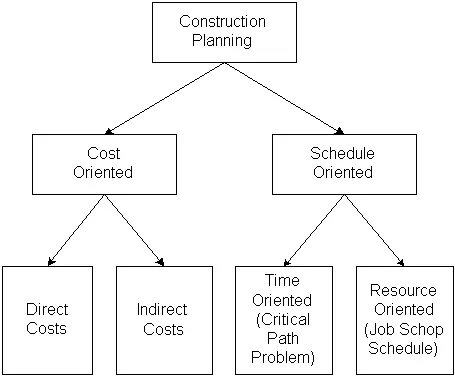
Alternative Emphases in Construction Planning
In this chapter, we shall consider the functional requirements for construction planning such as technology choice, work breakdown, and budgeting. Construction planning is not an activity which is restricted to the period after the award of a contract for construction. It should be an essential activity during the facility design. Also, if problems arise during construction, re-planning is required.
9.2 Choice of Technology and Construction Method
As in the development of appropriate alternatives for facility design, choices of appropriate technology and methods for construction are often ill-structured yet critical ingredients in the success of the project. For example, a decision whether to pump or to transport concrete in buckets will directly affect the cost and duration of tasks involved in building construction. A decision between these two alternatives should consider the relative costs, reliabilities, and availability of equipment for the two transport methods. Unfortunately, the exact implications of different methods depend upon numerous considerations for which information may be sketchy during the planning phase, such as the experience and expertise of workers or the particular underground condition at a site.
In selecting among alternative methods and technologies, it may be necessary to formulate a number of construction plans based on alternative methods or assumptions. Once the full plan is available, then the cost, time and reliability impacts of the alternative approaches can be reviewed. This examination of several alternatives is often made explicit in bidding competitions in which several alternative designs may be proposed or value engineering for alternative construction methods may be permitted. In this case, potential constructors may wish to prepare plans for each alternative design using the suggested construction method as well as to prepare plans for alternative construction methods which would be proposed as part of the value engineering process.
In forming a construction plan, a useful approach is to simulate the construction process either in the imagination of the planner or with a formal computer based simulation technique. By observing the result, comparisons among different plans or problems with the existing plan can be identified. For example, a decision to use a particular piece of equipment for an operation immediately leads to the question of whether or not there is sufficient access space for the equipment. Three dimensional geometric models in a computer aided design (CAD) system may be helpful in simulating space requirements for operations and for identifying any interferences. Similarly, problems in resource availability identified during the simulation of the construction process might be effectively forestalled by providing additional resources as part of the construction plan.
Example 9-1: A roadway rehabilitation
An example from a roadway rehabilitation project in Pittsburgh, PA can serve to illustrate the importance of good construction planning and the effect of technology choice. In this project, the decks on overpass bridges as well as the pavement on the highway itself were to be replaced. The initial construction plan was to work outward from each end of the overpass bridges while the highway surface was replaced below the bridges. As a result, access of equipment and concrete trucks to the overpass bridges was a considerable problem. However, the highway work could be staged so that each overpass bridge was accessible from below at prescribed times. By pumping concrete up to the overpass bridge deck from the highway below, costs were reduced and the work was accomplished much more quickly.
Example 9-2: Laser Leveling
An example of technology choice is the use of laser leveling equipment to improve the productivity of excavation and grading. In these systems, laser surveying equipment is erected on a site so that the relative height of mobile equipment is known exactly. This height measurement is accomplished by flashing a rotating laser light on a level plane across the construction site and observing exactly where the light shines on receptors on mobile equipment such as graders. Since laser light does not disperse appreciably, the height at which the laser shines anywhere on the construction site gives an accurate indication of the height of a receptor on a piece of mobile equipment. In turn, the receptor height can be used to measure the height of a blade, excavator bucket or other piece of equipment. Combined with electro-hydraulic control systems mounted on mobile equipment such as bulldozers, graders and scrapers, the height of excavation and grading blades can be precisely and automatically controlled in these systems. This automation of blade heights has reduced costs in some cases by over 80% and improved quality in the finished product, as measured by the desired amount of excavation or the extent to which a final grade achieves the desired angle. These systems also permit the use of smaller machines and less skilled operators. However, the use of these semi-automated systems require investments in the laser surveying equipment as well as modification to equipment to permit electronic feedback control units. Still, laser leveling appears to be an excellent technological choice in many instances.
9.3 Defining Work Tasks
At the same time that the choice of technology and general method are considered, a parallel step in the planning process is to define the various work tasks that must be accomplished. These work tasks represent the necessary framework to permit scheduling of construction activities, along with estimating the resources required by the individual work tasks, and any necessary precedences or required sequence among the tasks. The terms work "tasks" or "activities" are often used interchangeably in construction plans to refer to specific, defined items of work. In job shop or manufacturing terminology, a project would be called a "job" and an activity called an "operation", but the sense of the terms is equivalent. The scheduling problem is to determine an appropriate set of activity start time, resource allocations and completion times that will result in completion of the project in a timely and efficient fashion. Construction planning is the necessary fore-runner to scheduling. In this planning, defining work tasks, technology and construction method is typically done either simultaeously or in a series of iterations.
The definition of appropriate work tasks can be a laborious and tedious process, yet it represents the necessary information for application of formal scheduling procedures. Since construction projects can involve thousands of individual work tasks, this definition phase can also be expensive and time consuming. Fortunately, many tasks may be repeated in different parts of the facility or past facility construction plans can be used as general models for new projects. For example, the tasks involved in the construction of a building floor may be repeated with only minor differences for each of the floors in the building. Also, standard definitions and nomenclatures for most tasks exist. As a result, the individual planner defining work tasks does not have to approach each facet of the project entirely from scratch.
While repetition of activities in different locations or reproduction of activities from past projects reduces the work involved, there are very few computer aids for the process of defining activities. Databases and information systems can assist in the storage and recall of the activities associated with past projects as described in Chapter 14. For the scheduling process itself, numerous computer programs are available. But for the important task of defining activities, reliance on the skill, judgment and experience of the construction planner is likely to continue.
More formally, an activity is any subdivision of project tasks. The set of activities defined for a project should be comprehensive or completely exhaustive so that all necessary work tasks are included in one or more activities. Typically, each design element in the planned facility will have one or more associated project activities. Execution of an activity requires time and resources, including manpower and equipment, as described in the next section. The time required to perform an activity is called the duration of the activity. The beginning and the end of activities are signposts or milestones, indicating the progress of the project. Occasionally, it is useful to define activities which have no duration to mark important events. For example, receipt of equipment on the construction site may be defined as an activity since other activities would depend upon the equipment availability and the project manager might appreciate formal notice of the arrival. Similarly, receipt of regulatory approvals would also be specially marked in the project plan.
The extent of work involved in any one activity can vary tremendously in construction project plans. Indeed, it is common to begin with fairly coarse definitions of activities and then to further sub-divide tasks as the plan becomes better defined. As a result, the definition of activities evolves during the preparation of the plan. A result of this process is a natural hierarchy of activities with large, abstract functional activities repeatedly sub-divided into more and more specific sub-tasks. For example, the problem of placing concrete on site would have sub-activities associated with placing forms, installing reinforcing steel, pouring concrete, finishing the concrete, removing forms and others. Even more specifically, sub-tasks such as removal and cleaning of forms after concrete placement can be defined. Even further, the sub-task "clean concrete forms" could be subdivided into the various operations:
- Transport forms from on-site storage and unload onto the cleaning station.
- Position forms on the cleaning station.
- Wash forms with water.
- Clean concrete debris from the form's surface.
- Coat the form surface with an oil release agent for the next use.
- Unload the form from the cleaning station and transport to the storage location.
This detailed task breakdown of the activity "clean concrete forms" would not generally be done in standard construction planning, but it is essential in the process of programming or designing a robot to undertake this activity since the various specific tasks must be well defined for a robot implementation.
It is generally advantageous to introduce an explicit hierarchy of work activities for the purpose of simplifying the presentation and development of a schedule. For example, the initial plan might define a single activity associated with "site clearance." Later, this single activity might be sub-divided into "re-locating utilities," "removing vegetation," "grading", etc. However, these activities could continue to be identified as sub-activities under the general activity of "site clearance." This hierarchical structure also facilitates the preparation of summary charts and reports in which detailed operations are combined into aggregate or "super"-activities.
More formally, a hierarchical approach to work task definition decomposes the work activity into component parts in the form of a tree. Higher levels in the tree represent decision nodes or summary activities, while branches in the tree lead to smaller components and work activities. A variety of constraints among the various nodes may be defined or imposed, including precedence relationships among different tasks as defined below. Technology choices may be decomposed to decisions made at particular nodes in the tree. For example, choices on plumbing technology might be made without reference to choices for other functional activities.
Of course, numerous different activity hierarchies can be defined for each construction plan. For example, upper level activities might be related to facility components such as foundation elements, and then lower level activity divisions into the required construction operations might be made. Alternatively, upper level divisions might represent general types of activities such as electrical work, while lower work divisions represent the application of these operations to specific facility components. As a third alternative, initial divisions might represent different spatial locations in the planned facility. The choice of a hierarchy depends upon the desired scheme for summarizing work information and on the convenience of the planner. In computerized databases, multiple hierarchies can be stored so that different aggregations or views of the work breakdown structure can be obtained.
The number and detail of the activities in a construction plan is a matter of judgment or convention. Construction plans can easily range between less than a hundred to many thousand defined tasks, depending on the planner's decisions and the scope of the project. If subdivided activities are too refined, the size of the network becomes unwieldy and the cost of planning excessive. Sub-division yields no benefit if reasonably accurate estimates of activity durations and the required resources cannot be made at the detailed work breakdown level. On the other hand, if the specified activities are too coarse, it is impossible to develop realistic schedules and details of resource requirements during the project. More detailed task definitions permit better control and more realistic scheduling. It is useful to define separate work tasks for:
- those activities which involve different resources, or
- those activities which do not require continuous performance.
For example, the activity "prepare and check shop drawings" should be divided into a task for preparation and a task for checking since different individuals are involved in the two tasks and there may be a time lag between preparation and checking.
In practice, the proper level of detail will depend upon the size, importance and difficulty of the project as well as the specific scheduling and accounting procedures which are adopted. However, it is generally the case that most schedules are prepared with too little detail than too much. It is important to keep in mind that task definition will serve as the basis for scheduling, for communicating the construction plan and for construction monitoring. Completion of tasks will also often serve as a basis for progress payments from the owner. Thus, more detailed task definitions can be quite useful. But more detailed task breakdowns are only valuable to the extent that the resources required, durations and activity relationships are realistically estimated for each activity. Providing detailed work task breakdowns is not helpful without a commensurate effort to provide realistic resource requirement estimates. As more powerful, computer-based scheduling and monitoring procedures are introduced, the ease of defining and manipulating tasks will increase, and the number of work tasks can reasonably be expected to expand.
9.What is topographical survey? Why it is necessary for the metro rail project
Topographic Surveying. Topographic Surveying. determining the relative locations of points (places) on the earth's surface by measuring horizontal distances, differences in elevation and directions.
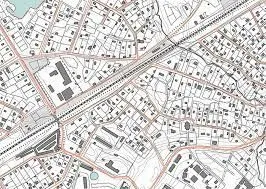
Topographic Surveying
Topographic Surveying
- determining the relative locations of points (places) on the earth's surface by measuring horizontal distances, differences in elevation and directions
- topos (Gr.): place; topographic maps give the locations of places (observable features); they serve as base maps
Use of topographic surveying in geography:
- producing topographic maps
- constructing topographic (cross-sectional) profiles
- establishing vertical and horizontal control for accurately defining locations
General Principles
-
select a scale in advance; this determines the plotable error
-
work from the most accurate to the least accurate methods
-
orient each survey, preferably with respect to true north
-
the first stage of surveying is always establishing horizontal and vertical control: the distance, direction and difference in elevation between key fixed points
-
establish a survey plan that includes checks on accuracy, e.g. redundant points, pacing of measured distances, surveying between fixed positions, etc.
Methods
- horizontal distance
- tachymetry: a rapid optical means of measuring distance using a telescope with cross hairs and a stadia rod (one stadium = about 607 feet)
- measuring slopes distance with a tape and reducing it to horizontal distance using the cosine of the slope gradient
- difference in elevation
- leveling with a level telescope and a stadia rod, or
- measuring a vertical angles and a slope distance (height is the product of the distance and sine of the angle)
Leveling is more accurate since elevation differences are measured not calculated. Two readings are taken at each position of the automatic level: a backsight towards a station located before the level on the traverse and a foresight to the next station on the traverse. Thus the stadia rod occupies two stations, before and after the level on the survey. The difference in elevation between successive stations if the difference between the backsight and the foresight read from the stadia rod. For each position of the level, the lengths of the foresights and backsights should be approximately the same since accuracy is a function of the distance of a sighting. The level operator should anticipate the distance to the next station and set up the level midway along this distance (note: the distance that can be sighted decreases with increase in slope, since the stadia rod will disappear above or below the level line of sight). The lengths of backsight and foresight can be paced by the rod person or measured by the interval between the upper and lower cross hairs (tachymetry).
- direction
- horizontal angle measured with a compass
- precise measuring devices use vernier scales
- direction is expressed relative to a reference line or meridian
- true meridian: a north-south line
- magnetic meridian: a line parallel with the earth's magnetic lines of force
- assumed meridian: an arbitrary line
- bearing: angles expressed relative to a meridian using the quadrant and an acute angle, e.g. N37oE, S62oE, N20oW
- azimuth: the clockwise angle from the north branch of a meridian, e.g. 45o (northeast), 180o (south)
- deflection angle: the angle between a line and the prolongation of a preceding line; it is a right or left angle depending on whether the new line is right (clockwise) or left (counterclockwise) of the preceding line
- interior angle: an angle inside a closed polygon
Types of Traverses
- azimuth: along a single direction (azimuth); common for slope profile surveys where the profile is always perpendicular to contours (i.e. maximum slope angle)
- closed traverse: begins and ends at fixed control points of known location; permits calculation and adjustment for closure error
- closed-loop traverse: begins and ends at the same station; permits calculation and adjustment for closure error and use of interior and deflection angles
- open traverse: surveying from a known position to a point of unknown position; does not enable computational checks for error, rather all measurements must be repeated to check for error
Shape Of The Earth And Error: The two basic problems in topographic surveying
The shape of the earth (the geoid) is a consideration only in geodetic surveying, where over long distances flat surfaces are not level, plumb lines are not parallel and the sum of the angles in a triangle is greater than 180o; thus precise surveys over large areas employ the principles of geodesy (the mathematical properties of an ellipsoid that emulates the earth); however with most surveys, including virtually all topographic surveying in geography, the departure of horizontal lines from level and plane angles from spherical angles are negligible and can be ignored
plane surveying: where the earth's surface is regarded as a plane; level lines are considered straight, angles are considered to be plane angles and plumb lines are considered to be parallel within the survey
with these assumptions, the relative locations of points can be calculated using the principles of plane trigonometry:
- for right angles: sinA = a/c, sinB = b/c, and c2 = (a2 + b2), where A & B are the acute angles, C is the right angle and a, b & c are the sides opposite the angles designated with the same letter; thus the sides and angles can be calculated with a knowledge of 1 side and 1 angle or 2 sides
- for oblique triangles: a/sinA = b/sinB = c/sinC; thus given 2 angles and one side or 2 sides and 1 angle are the other sides and angles can be calculated
Error
Distances and angles can never be determined exactly; measurements are subject to error. Error can be controlled through procedure and instrumentation. Surveys are conducted according to standard levels of accuracy (first order, second order, etc.). The desired level of accuracy depends on the intended us of the survey data (e.g. locating permanent stations or surveying bridges and dams versus surveying for terrain analysis or orienteering).
For topographic mapping, the desired level accuracy is the plottable error, the shortest distance that can be depicted on a map at a given scale. The drafting of lines generally is accurate to within 0.25 mm. At 1:1000, 0.25 = 250 mm or 0.25 m on the ground. Optical measuring devices will provide this level of accuracy. At 1:25,000, 0.25 mm = 6.25 m on the ground. Pacing of distance will provide this level of accuracy, although in practise accuracy is greater than the plottable error by as much as one-third (e.g. 80 mm rather than 250 mm at a scale of 1:250,000) so that plotting and surveying errors are not compounded.
Adjusting For Closure Error
Horizontal angles
- In a closed polygon, the sum of the interior angles = 180o (n-2), where n is the number of sides in the polygon, thus the sum of the horizontal angles in a triangle (n = 3) is 180o; an equal angle is subtracted or added to each measurement to satisfy the equation for interior angles; if the closure error is not equally divisible by n, make the largest adjustments to the largest angles.
- The sum of deflection angles for any closed polygon is always 360o; this provides for another means of determining and adjusting for closure error.
Difference in elevation
Closure error can be determined for closed and closed-loop traverses. The closure error can be divided by the number of stations on the traverse or the correction at each station can be calculated according to the distance from the origin of the survey:
Ci = di/L * Ec, where
- Ci = the correction applied to station I
- di = the distance to station i from the origin of the
traverse - L = the total length of the traverse
- Ec = the closure error
This method accounts for the propagation of error with distance.
Horizontal distances
As with leveling, closure error can be determined for closed and closed-loop traverses, where the coordinates of the end points are identical or known. Location in the horizontal plane are given by x and y coordinates (e.g. northing and easting). Using the measured horizontal distances and adjusted angles, calculate the coordinates of each station. The difference between the calculated and known coordinates of the end control point is dx and dy, the closure error in x and y. As with leveling, the adjustment is a function of the distance traversed (Li) relative to the total length of the traverse (L):
Cdxi = dx * Li/L Cdyi = dy * Lii/L, where Cdxi and Cdyi are the adjustments in x and y coordinates at station i
The relative accuracy of distance measurements can be expressed as ((dx2 + dy2)1/2)/L. An angular error of one minute is equivalent to a distance measurement error of 3 cm over a distance of 100 m, since the sine of 1/60o is .00029.
Why it is necessary for the metro rail project
Surveying - Before starting any Railway and Metro project Surveying is the first engineering work.The state of art of survey of Railway and metro project is very important .
Map Study or Paper location - Before the actual work starts , study of available map of the area should be made .Generally the survey map of india or Arial maps of india used . The map show the contours , topographical features and physical land , building , Rivers and another things . The study of maps prior to actual survey work is known as map study or paper location .
Types of survey - •Traffic Survey
•Reconnaissance survey
•Preliminary survey or Survey for initial location
•Detailed survey or survey for final location
Traffic Survey - The objective of traffic survey is to make accurate determination of the potential of available traffic .In this traffic survey Survey of population ,locality , agriculture , Industrial , mineral , forest , future possibilities and develop traders , future business ,And selecting which types of construction B.G/M.G/N.G/Metro/monorail high speed , Bullet train , Freight corridor .Field survey carried information and important maps are prepared for study .(a). Topology – Showing all physical features ( Land , Building , rivers , bridge , tunnels , existing routes , contours etc .)(b). Agricultural Maps (c). Industrial Maps
Reconnaissance Survey - •This is rough and rapid inspection , both visual and instrumental .In this Reconnaissance survey (a). Acquire the knowledge of physical features of the country like the rivers , valley , cultivated lands , forest , hills , existing roads , canals etc .(b). All possible alignment marked on the map , during map study for construction new Railway .•Equipment used in Reconnaissance survey – •A Prismatic compass •An Abney level (Hand level clinometer ) •A Barometer and a Thermometer •A pair of powerful Binoculars or a Telescope .•A Pedometer
Preliminary Survey (Initial Location Survey ) - •In this survey •Length of route , gradients , along the alignment , Quality of earth work , details of structure , bridge , culvert , canal crossing ,Level crossing , availability of labour , drinking water facilities ,Details of acquisition of land , the climate condition of route .Instrument used for Preliminary survey - Theodolite , A techenometer, A dumpy level Plane table Prismatic compass
- What are the hindrances that could be there whilst planning to connect any to two stations in a city during metro construction?
he public transportation system in most of the cities in India is grossly inadequate and can be considered inefficient or insufficient at large. In order to improve the public transportation system, the government has provided the Metro and the mass rapid transit system (MRTS) in some of the major cities of the country or they are being planned in various cities to reduce the spiralling problem of traffic congestion.
Experts believe as the population of a city grows share of public transportation — road or rail based — should increase for a city. According to a report by Sekar & Karthigeyan “For a population of 1 or 2 million the share of public transportation should be about 50 per cent–60 per cent. Moreover the percentage share of public transport should progressively increase with the population growth of the city, and should reach about 75 per cent when the population of the city reaches the 5 million mark.”
The selection of a public transport system on a corridor in a city whether it should be road based or rail-based — metro rail or mono rail, primarily depends on the traffic density during the peak hours on that particular corridor.
Past records of Indian cities have shown that under mixed traffic conditions, comprising slow and fast moving vehicles, road-based public transportation system can optimally carry around 8,000 people per hour per direction (phpdt). However, once the density of traffic crosses 15,000 phpdt, introduction of a metro rail system becomes unavoidable. Metro rail is a form of mass transit public transport system employing trains. The metro rail system, unlike conventional rail-based systems is separated from the other traffic or provided with separate right of way (ROW) to avoid conflict with other urban transportation networks. In most of the cases, at least a portion of the rails are placed underground (in tunnels), while a major portion remains above ground (elevated). The system is provided in an urban area and is mostly operated by electricity with high capacity and frequency.
Challenges of a Metro system:
Though metro trains are a necessity they come with various challenges of their own. Some of them are like Financial viability of metro projects, over or under-estimation of traffic, Land and property acquisition and resettlement issues, loss of green cover, noise pollution, and
vibration issue.
The financial viability of any metro project greatly depends on the accuracy of traffic demand forecasts and ridership estimation. These forecasts not only provide a technical justification for these projects, but also act as a guide for their socio-economic and environmental appraisal against their projects cost estimates. However, most of these forecasts have often led to inaccurate or misleading picture about the project, forcing policy makers to take a wrong decision.
In the context of metro rail projects, an over-estimation of the ridership figure has led to an over-sizing and under-utilisation of the infrastructure resources across the world. This has created over-investment in idle capacities and resulted in financial mismanagement or crisis for the project. On the other side, an under-estimation of traffic demand or ridership have led to chaos and inefficiency and ultimately further investment as adding capacity to an existing facility is much more costlier than building the whole capacity in one go.
According to a report by S Gangopadhyay on Indian Metro system, the demand forecasts for metro rail projects in Indian cities have not been accurate. In the first metro rail project in India for the Kolkata metro, the annual passenger volume estimated was 623.7 million trips for the year 2000, however, the actual number of passenger trips on the metro railway during 1999–2000 was only 55.8 million, which is around one-eleventh of the estimated traffic in 1990. Similarly, expected ridership of the Delhi metro rail has been modified several times since the commencement of the project in year 2002. The Delhi Metro Rail Corporation had initially expected ridership of metro rail to be 1.5 million passenger trips per day (ppd) for 2005, which was further reduced to 0.7 million ppd by March, 2006. However, the traffic has improved now with increased network of metro in various cities, the gap between projection and reality is still wide.
A data analysis of Metro traffic in seven major cities, including Delhi, Kolkata, Bengaluru, Hyderabad, Jaipur, Chennai and Mumbai shows that barring Delhi, no other Metro service has a daily footfall of over 1 million. Delhi has a footfall of around 2.5 million. Besides, the average Metro fares per kilometre in India ranges between Rs 1 and Rs 3.5 per km. Mumbai Metro is the most expensive, while Kolkata Metro is the cheapest with an average fare of Rs 0.9 per km .
Land Acquisition, Resettlement and Rehabilitation (R&R) related Issues:
Metro cities of developing countries throughout the world are densely populated with little availability of land for such mega infrastructure projects. Land acquisition has always been an integral part of any mega infrastructure project. Efforts are always made to minimise the land acquisition as to minimise its socio-economic impacts. The land acquisition in some areas along the metro corridors sometimes becomes inevitable as no other option related to lower resettlement impact is feasible due to technical reasons.
The issue of land acquisition is a pre-construction phase activity, for which proper socio-economic and R&R surveys need to be carried out to determine the project affected persons. In Delhi, most of the elevated metro corridors are provided along existing roads or the medians of the roads which are mostly owned by the government agencies so that the various impacts related to land acquisition are minimum. Providing metro rail corridors on the one side of existing road corridors ensures that there is no or very minimum additional land acquired by using the existing ROW of the road for metro rail corridors.
In the central business district (CBD) areas and archeologically sensitive areas the metro rail corridor goes underground. Many times some land is acquired temporarily for material storage or to facilitate safety during the construction phase, which is returned to the original owners after the construction.
So we can say that land acquisition for metro rail projects is inevitable. However, it should be kept to a minimum by adopting suitable route alignment and by employing the latest construction techniques which reduce the material and land acquisitions and also result in a reduced overall cost of the project, affecting the financial viability of the project.
Property development along Metro Rail Corridors: Property development along the metro rail corridors and metro stations have always been a debatable issue and also generated arguments both in support as well as against it. While many argue that organisations like DMRC in Delhi and similar organisations in other parts of the country, who have been entrusted the job of construction and operation of metro rail system(s), should not be allowed to venture into property development business like any other real estate developers, when the land to these agencies have been given to them at concessional rates. However, metro rail agencies have always argued that the earnings from the property developments have been mandated by the government to finance various on-going projects related to property development. Commercial use of property along the metro corridors is not unique for DMRC in Delhi or any other part of India or even in the world.
As the construction and operating cost of metro rail projects increase, coupled with reduced financial support from the government , international agencies, property development and commercial use of property are the only resources available by which the metro rail projects and their operations can be sustained in the long run. That too without compromising the main objective of providing a safe, economical and comfortable mode of public transportation, said experts.
11.What are underground utilities which would be there existing under the ground level. Also mention some other utilities apart from the ones mentioned in the course.
Underground utilities are any public service infrastructures installed beneath the ground surface. Underground utilities include electric cables, telecommunication and data cables, water and sewer pipelines, and gas and oil pipelines. These utility lines are often a lifeline of human society and help a community to function properly. They are usually installed beneath the ground for convenience, safety, and aesthetic reasons.
New utility lines are being installed underground by default, however some older utility lines are still above ground and need to be buried. This is especially true for overhead electric cables that can topple in areas prone to high winds such as during a hurricane or a tornado.
Water, gas, and oil pipelines installed on the ground surface are prone to theft and vandalism and hence are best buried underground.
Underground utility infrastructure is typically installed and maintained by relevant public utility companies. The utility companies responsible for their installation must typically seek approval from local government authorities before construction commences to ensure that the intended utility location is within the appropriate right-of-way.
The installation of underground utilities is usually done by conventional exavaction methods, but now trenchless installation methods are also being used widely. Conventional excavation methods pose many risks to construction workers due to confined spaces, engulfment, electrocution, and unstable trenches. They also take up a large amount of space and cause significant surface disruption.
Trenchless methods on the other hand are less disruptive, and many governments and municipalities are turning to trenchless methods of underground utility installation. horizontal drilling has quickly gained popularity due to its remote steering ability, reduced manual labor requirement, and minimal impact on the surrounding environment.
Underground utilities are also known as subsurface utilities.
Challenges in Piping Design
Piping design is an integral part of engineering services. There are two components to Piping design: Piping Modeling and Piping Stress. Both are critical for developing efficient piping processes to find out the best way to transport fluids or gas. The best way here means the safest, most efficient and cost-effective design for the process. However, piping systems are intricate frameworks spanning the industrial complex. Poor design or design failure can have disastrous consequences – jeopardizing the safety of employees and resulting in a halt in production, extensive repairs and financial losses.
An intelligent design is the backbone of an accurate and safe piping system. Developing a piping system design that senses and controls the pressure, load, flow rate and temperature of the transmitted fluid or gas can be somewhat tricky. Companies developing or outsourcing their underground piping design need to be especially cautious and heedful of the many difficulties that crop up while architecting their engineering piping.
Choosing the right material
The success of the project hinges on the accuracy of piping materials suggested and designed during 3D Modeling. This depends on an accurate understanding of the process be it pharmaceutical, power, petrochemicals etc. The requirement specifications from the design team should include process data sheets, equipment data sheets and other niche disciplinary details for accurate designing and materials. The design engineer also needs to consider issues like the amount of pressure, the width of piping, the components used in the process, when selecting the construction material.
Temperature and weather conditions
Piping design companies must also analyze and customize the designs based on the temperature and weather conditions of the process plant. The dimensioning and tolerances are different for colder climates and tropical zones. Several codes like ASME, ASTM, ISO, SAE, ANSI, BS, DIN and MIL are applicable to specific oil and gas facilities depending on the location and weather conditions. The design team/partner must verify what regulations, codes and standards will apply for the specific process, materials used and project location. Poor knowledge or implementation of these standards in designing can have severe consequences for the project.
For instance, piping design in the U.S, on offshore facilities is regulated in accordance with ANSI/ASME Standard B31.3. Whereas most onshore facilities are mandated to adhere with ANSI/ASME Standard B31.4 or B31.8, depending on whether it is an oil or gas facility. Similarly, various codes apply for various engineering disciplines be it Oil and Gas, Petrochemicals, Power and based on the fluids and materials used. Failing to interpret and execute correctly can hamper the project.
As per the press release of DMRC, in the earlier phases of construction, erection of U-girders was done with the help of two cranes of capacity 350/400T which were placed at each pier location, and the U-girders were transported at each pier location with the help of a long trailer having an approximate length of 42m. In a congested urban area like Delhi, it used to be very challenging to find adequate space for positioning these heavy capacity cranes which occupy a lot of space. In addition, transporting the U-girders of 28m length with such long trailers was also a herculean task as roads in the NCR are either too congested or have massive traffic volumes even during the nighttime. These limitations often discouraged the use of U-girders in construction in spite of the fact that the U-girders are the most suitable structures for viaducts in terms of cost and time.
According to DMRC, this new state-of-the-art Launcher with Transporter is fully electric with much higher output in comparison to the conventional launchers/cranes. The Transporter carries the U-girder from one designated point and moves forward on rails laid on the already erected U-girders to further add more U-girders from the feeding point to the launcher. As a result, the U-girders are to be transported on trailer only up to the feeding point identified at a suitable location and not for the entire length of work. This results in much less requirement of space.
Through this new Launcher with Transporter, 4 to 6 U-girders per day can be erected on an average whereas, with the conventional method, about 2 U-girders can be done in congested working environments like in Delhi – NCR. The erection work of U-girders with conventional cranes can be done only during the night as it requires blocking of roads to position the cranes. Whereas in case of this new technology, U-girders are transported with the Transporter on the erected viaduct without any interface with road from a single identified feeding point. This technology is being used for the first time in India.
The Launcher today has been made operational for the construction of a 9.5 km long
viaduct from Mukarba Chowk to Ashok Vihar covering four stations namely Bhalswa, Majlis Park, Azadpur and Ashok Vihar and a connection to depot from Majlis Par.
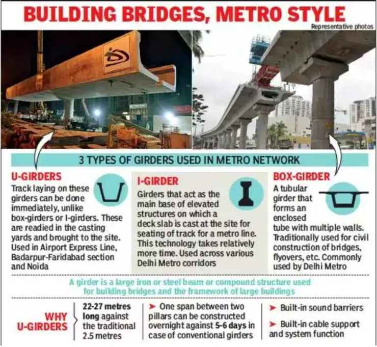
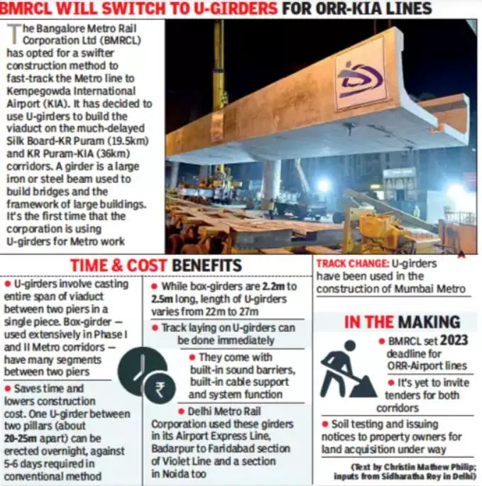
The Bangalore Metro Rail Corporation Limited (BMRCL) has launched the first ever U Girder on the ORR-Airport line. The first U Girder span was placed between two pillars near Bagmane Tech Park on Saturday night.
BMRCL officials said that use of the U Girder on this line will help in expediting the project. In phase I and phase II of the project, the BMRCL had used a box girder to build the elevated corridor. Earlier, to place ten segments of the box girder, the BMRCL needed 5 to 6 days even with the help of huge cranes. But now, the single span of the U girder can be erected overnight.
Metro projects across the world are extensively using U-girders, which saves time in construction besides ensuring better quality. After casting, these girders are brought to the site and launched with the help of high capacity cranes or luncher.
14.What are advantages of precast girders in an elevated metro? Explain in detail about the how it is efficient over the cast in-situ girders?
- Saves Construction Time: Precast Concrete construction saves time, the risk of project delay is also less. The precast concrete casting can be carried on simultaneously with other works on site such as earthwork, survey etc. and thus saves time.
- Quality Assurance: The key factors which regulate the quality of construction such as curing, temperature, mix design, formwork, etc. can be monitored for Precast Concrete. So, improved quality construction can be performed.
- Usage of Prestressed Concrete: By using pre-stressed precast, structural materials of high strength and load-bearing capacity can be achieved, which can result in greater clear span, reduced size of the cross-section of structural members, etc.
- Cost-effective: The simplified construction process reduces the time, increases the productivity, quality and safety and thus the cost is reduced.
- Durability: Precast Concrete structure has a longer service time period and minimal maintenance. The high-density Precast concret is more durable to acid attack, corrosion, impact, reduces surface voids and resists the accumulation of dust.
- Aesthetics: As the structures are prefabricated in a controlled factory environment, several combinations of colors and textures can be used. A wide range of shapes and sizes are available to choose from with smooth finishing and thus the aesthetical value of products are increased.
- Safe Construction Platform: No raw materials have to be stocked in site for Precast Concrete construction. It reduces the requirement of traditional formworks and props, wastage, workers, etc. and thus provides a safe working platform.
01. Definition
- According to ‘Precast Concrete Institute, U.S.A’ (Published in: Designing with Precast and Prestressed Concrete), precast concrete is cast into a specific shape at a location other than building site like factories. The concrete is placed into a form, typically wood or steel, and is cured. These components are then transported to the construction site for erection into place. Precast concrete can be plant-cast or site-cast.
- According to ‘Edward Allen and Joseph Iano’ (Author of Fundamental of Building Construction Materials & Methods), cast-in-situ concrete is cast into forms on the building site. It offers unlimited possibilities to the designer for any shape formation with a limitless selection of surface textures.
02. Casting
- In the precast concrete, elements are manufactured in a controlled casting environment and hence it is easier to control mix, placement and curing.
- Elements can be cast in advance and held until the hour you need them, thereby saves time.
- Weather condition has no effect on casting work.
- In the cast-in-situ concrete, column, slab etc. elements are casted on site in the open environment and hence it is difficult to control mix, placement and curing.
- Elements cannot be casted in advance.
- Weather condition can delay the casting work.
03. Quality Control
- Quality can be controlled and maintained easily.
- Quality control and maintenance is difficult.
04. Cost
- Precast concrete is cheaper form of construction if large structures are to be constructed.
- Maintenance cost of precast concrete structure is higher.
- In situ concrete is cheaper form of construction for small structures.
- Maintenance cost of cast-in-situ concrete structure is less compared to the precast concrete structure.
05. Requirement of Worker & Machinery
- Less labours are required.
- Skilled labours are required at construction site.
- Skilled and technical contractor is required for construction of the precast concrete structure.
- Precast concrete requires heavy machinery and cranes for handling i.e. lifting and installation of heavy elements
- More labours are required.
- Skilled labours are required at construction site.
- Local contractors can also build the structure.
- Cast-in-situ concrete does not require such handling equipment.
06. Strength
- Precast concrete construction is quick as it can be installed immediately and there is no waiting for it to gain strength.
- Increase in strength can be achieved by accelerated curing.
- On site strength test is not required.
- High strength concrete can be used because it is in controlled condition.
- In situ concrete construction is slow as gaining of strength requires time.
- Increase in strength at situ by accelerated curing is a difficult task.
- On site strength test is required.
- It will difficult to use high strength concrete as it depends on site condition and resources available.
07. Time of Construction
- Total construction time is less as compared to cast-in-situ.
- Speedy construction is possible.
- Total construction time is more as compared to precast.
- Speed is less as elements are casted at site.
08. Technical Points
- Large number of joints in structural system.
- Less resistant to Earthquake and wind forces not recommended where seismic loads are dominant.
- In precast concrete construction, details at the joint become very critical and needs careful attention.
- The elements have to be designed for handling stress or loads during handling, which may or may not increase steel.
- Elements of varying lengths and shape can be developed.
- Precast concrete does not offer a monolithic architectural character.
- Less number of joints present in structural system.
- More resistant to earthquake and wind forces.
- Elements cannot be casted in advance.
- Elements are not to be designed for any such loads or stress.
- There is constraint in length and shape of element.
- In situ concrete offers a monolithic architectural character.
In the final note, precast & cast-in-situ concrete both are the easy construction technics. Both methods have their advances such as precast concrete construction gives cost benefits on a large project, quality assurance due to control casting condition, reduces the high supervision of concreting process like mixing, placing etc. at the construction site. On the other side, cast-in-situ concrete is the conventional method for concreting, it is very and largely used for construction, and any local contractor can adopt this method.