Challenge 2
CHALLENGES 2
- What are the structural components of a bridge? Explain in detail about the foundation, sub structure and super structure components of the bridge.
ANS-
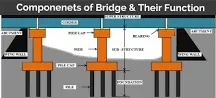
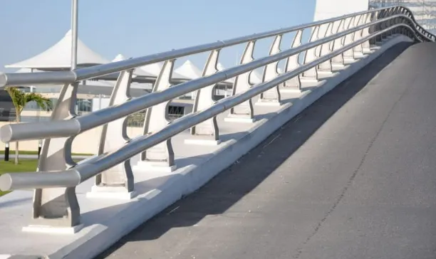
- Abutments.
- Piers.
- Wing Walls.
- Beam & Girders.
- Bearing.
- Arch & Cables.
- Parapet Wall and Handrail.
- Flooring.
1. Spread Foundation
The spread foundation is additionally called an open foundation and is reasonable for bridge foundation of normal tallness based on a firm and dry ground to offer help for the construction. This types of bridge foundation is appropriate where there is least scouring and the hard grounds starts from 1.5m – 3m underneath the level of the watercourse.
2. Raft Foundation
These types of bridge foundation are generally utilized where there passable bearing limit of the soil is less and the watercourse bed contains delicate clay and silt. It favors foundations where hard soil isn’t found inside sensible profundity of 1.5m – 2.5m, beneath the watercourse.
3. Pile Foundation Bridge
PILE FOUNDATION is the types of bridge foundation that is utilized in conditions where there is extremely delicate soil and hard strata are not accessible at a sensible profundity. It is likewise utilized where scouring of a river as to be done and a enormous concentrated load is to be taken by the foundation.
4. Well Foundation Bridge
WELL FOUNDATION of bridge is the types of bridge foundation that is utilized when the bed has SANDY SOILalso, hard soil is accessible at 3 – 4 m beneath the level of the watercourse. Most appropriate on soil a cotton having delicate soils what’s more, sandy soils and weighty scouring is relied upon due to the huge velocity of approach of the river.
5. Caisson Bridge Foundation
CAISSON BRIDGE FOUNDATION is a types of bridge foundation that is utilized where there is a hard layer close to the river bed and there is exorbitant water profundity that isn’t monetarily strong to eliminate the empower sinking wells for well foundation.
6. Grillage Foundation
This types of bridge foundation is reasonable for weighty and separated footings of wharfs where deep foundations are to be stayed away from. GRILLAGE FOUNDATIONis most appropriate where sub soil conditions are poor.
7. Inverted Arc Foundation
This types of BRIDGE foundation is appropriate when the profundity of unearthing for foundation is less. ARCH BRIDGE s most appropriate where the bearing limit of the soil is less, particularly when the sub soil has some delicate pockets and there is plausibility of inconsistent settlement.
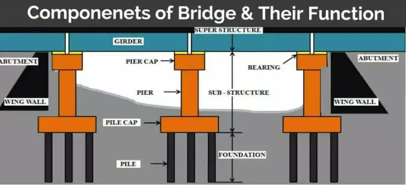
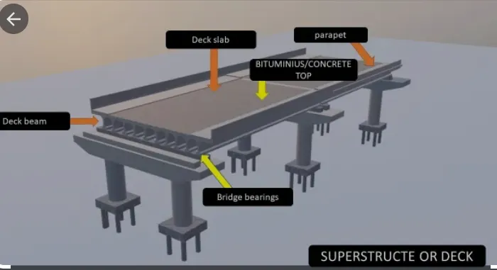
superimposed dead load is the dead load on the structure after slab and beams have been casted .. dead load is the load from slabs and columns and beams.
superimposed load: The load superimposed on the dead load of a building. The term is generally synonymous with live load, although a distinction is sometimes made between the superimposed dead load caused by movable partitions, etc., and the live load caused by people.
- What are the different types of girders that can be used for a metro viaduct?
ans- Use U type girders in metro viaduct
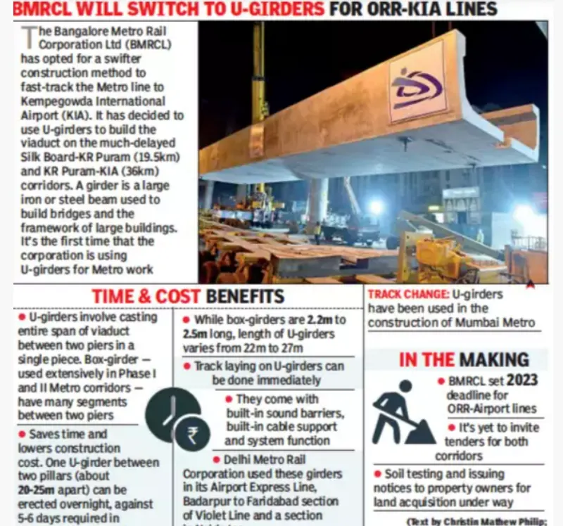
I GIRDER UESD IN METRO VIADUCT
BOX GIRDER USED IN METRO VIADUCT
BUT U GIRDER USED METRO IN BECAUSE IT PROVIDE SAFTY AND BENFICIAL FOR METRO
4.What are bearings in a metro viaduct. Explain the types of bearings and analyses the types with respect to their advantages and disadvantage.
- Deep-Groove Ball Bearings. The most commonly used bearings are Deep-Groove Ball Bearings. ...
- Angular Contact Ball Bearings. ...
- Self-Aligning Ball Bearings. ...
- Thrust Ball Bearings. ...
- Spherical Roller Bearings. ...
- Cylindrical Roller Bearings. ...
- Tapered Roller Bearings. ...
- Needle Roller Bearings.
ADVANTAGE
5.During the construction of metro viaducts across water passages, explain the topographical check list that needs to be considered for the designing the height of the viaducts?
ANS- The piers, two in number having a height of 24 metres from its base and a diameter of two metres.
and 27 metre when constructed the metro viaduct
2. Types of Topographic Surveys
Topographic surveys are performed for the master planning, design, and
construction of installations, buildings, housing complexes, roadways, airport
facilities, flood control structures, navigation locks, etc. Some of the more common
surveys are described below:
2.1 General/Preliminary Site Plans
General or Preliminary site plans shall performed at scales from 1:2,000 to 1:5,000.
They depict general layout for potential construction, proposed transportation
systems, training areas, and existing facilities.
2.2 Detailed Topographic Surveys for Construction Plans
These surveys are performed at scales from 1:200 to 1:2,000 and at varying contour
intervals. They are performed to prepare a base map for detailed site plans (general
site layout plan, utility plan, grading plan, paving plan, airfield plan, demolition plan,
etc.). The scope of mapping is confined to an existing/proposed building area. These
drawings are used as a base for subsequent as-built drawings of facilities and utility
layout maps, i.e., Amenity Mapping / Facility Management (AM/FM) databases.
2.3 As-Built Surveys and Amenity Mapping (AM)/Facility Management
What Is a Topographic Map
There are many different kinds of maps for many different purposes. Just like you would not use a globe to navigate a road trip, road maps are not much help for depicting land features. Topography is the study of the land surface. Topographical maps are special types of maps that show the different land features. Topographical maps can be used to determine where the landscape is flat and where it is dominated by mountains. You can also identify valleys, canyons, and hillsides. A normal map is a flat model of all or part of Earth's surface drawn to a specific scale. Topographic maps show the elevation of different landforms above sea level.
Features
A topographic map is a detailed and accurate illustration of man-made and natural features on the ground such as roads, railways, power transmission lines, contours, elevations, rivers, lakes, and geographical names. Since they represent the Earth's features accurately and to scale on a two-dimensional surface they are an excellent planning tool and guide and, at the same time, help make outdoor adventures enjoyable and safe.
Topographic maps identify numerous ground features, which can be grouped into the following categories:
- Relief: mountains, valleys, slopes, depressions as defined by contours
- Hydrography: lakes, rivers, streams, swamps, rapids, falls
- Vegetation: wooded areas
- Transportation: roads, trails, railways, bridges, airports/airfields, seaplane anchorages
- Culture: buildings, urban development, power transmission line, pipelines, towers
- Boundaries: international, provincial/territorial, administrative, recreational, geographical
- Toponymy: place names, water feature names, landform names, boundary names
Contour Lines
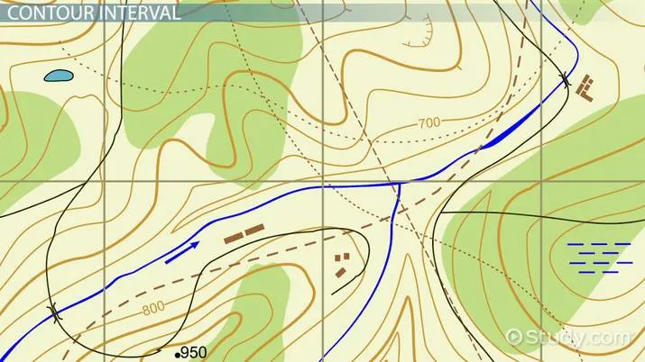
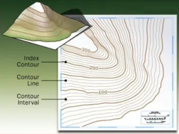
Topographic maps have contour lines that show how the elevation of the landscape changes. Contour lines are imaginary lines on Earth's surface that connect points that are the same height above sea level. On this map, the contour lines look like concentric circles. The outside line is at sea level, which means it has an elevation of zero meters above sea level. The next contour line has an elevation of 10 meters above sea level. The line above that has an elevation of 20 meters above sea level. Contour lines connect points that share the same elevation: Where they are close together (they never intersect), elevation is changing rapidly in short distance and the terrain is steep. Where contour lines are wide apart, elevation is changing slowly, indicating a gentle slope. In this example, the contour lines are evenly spaced apart. This indicates that the slope of the hill is an even and steady curve of elevation from top to bottom.
 |
Contour Interval
A contour interval is the difference in elevation between any two adjacent contour lines. In this case, the contour interval is 10 meters. Note how the contour lines at 0 and 50 meters are thicker than the rest of the lines. These are known as index contour lines. Index contour lines are usually identified every fourth or fifth line on a topographic map. Index contour lines make it easier to read elevation levels, much like chapters in a book.
What Is A Topographic Map Used For
Topographic maps are very useful for hikers, skiers, and others seeking outdoor recreation. They are also essential tools of the trade for geologists, surveyors, engineers, construction workers, landscape planners, architects, biologists, and many other professions, especially people in the military. Armies throughout history have used information on elevation, hills, water, and other landforms when planning their military strategy. They are also used by the government and industry to assist with urban planning, mining, emergency management, and the establishment of legal boundaries and land ownership. In agriculture, topography maps are used to determine how soil can be conserved and how water will flow over the land. They can help scientists to determine how water and wind may cause erosion and establish conservation areas such as watersheds and wind blocks.
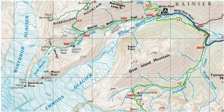
Topographic Map Example
 |
6.What are the different types of girders that can be used in a metro viaduct construction? Explain the differences of the girders and elucidate how a designer has to choose his girder type whilst designing.
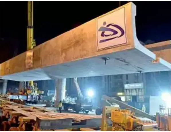
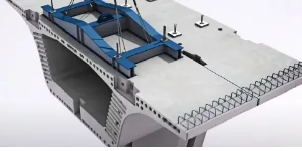
bridge’) is a relatively new and innovative concept in
bridge deck design. U-shaped girder is appropriate when a
new or modified alignment structure requires an increase in
the vertical clearance beneath the bridge. The bridge deck,
made of prestressed concrete (PSC), has other important
advantages,
pollution, aesthetic appearance, reduced construction time,
durability and economy. This concept can be used for
overpasses, under-crossings, viaducts, etc.
- Saves Construction Time: Precast Concrete construction saves time, the risk of project delay is also less. The precast concrete casting can be carried on simultaneously with other works on site such as earthwork, survey The key factors which regulate the quality of construction such as curing, temperature, mix design, formwork, etc. can be monitored for Precast Concrete. So, improved quality construction can be performed.
- Usage of Prestressed Concrete: By using pre-stressed precast, structural materials of high strength and load-bearing capacity can be achieved, which can result in greater clear span, reduced size of the cross-section of structural members, etc.
- Cost-effective: The simplified construction process reduces the time, increases the productivity, quality and safety and thus the cost is reduced.
- Durability: Precast Concrete structure has a longer service time period and minimal maintenance. The high-density Precast concrete is more durable to acid attack, corrosion, impact, reduces surface voids and resists the accumulation of dust.
- Aesthetics: As the structures are prefabricated in a controlled factory environment, several combinations of colors and textures can be used. A wide range of shapes and sizes are available to choose from with smooth finishing and thus the aesthetical value of products are increased.
- Safe Construction Platform: No raw materials have to be stocked in site for Precast Concrete construction. It reduces the requirement of traditional formworks and props, wastage, workers, etc. and thus provides a safe working platform.
- Strength-to-Weight and. Multi-Directional Strength. ...
- Economy. A high strength-to-weight ratio coupled with low price per pound of steel joists contributes signifi- cantly to lower building costs. ...
- Cost-Saving Ease of Erection. ...
- Durability
- Fire Resistance.
1. Plate 542x16x9451
Bott. Flange Plate 150x20x
Top Flange Plate 642x20x9026
Batten Plate 480x10x518
Lacing Plates 65x10x542
Diaph. Plate 450x10x572(4 nos)
B- DIMENSIONS
Intersection 9630
Top Plate Length 9026
Overall Length 9451
Box width 610
Distance between group of holes
Web 1st
Row 7582
Web 5
th Row 7862
Top flange inner 8361