Project 2
MESHING OF FLOOR PANEL
AIM
To extract midsurface of Floor panel and to mesh the midsurface by adhering to the quality criteria as given below.
| S.N | Quality Criteria | Value |
| 1 | Aspect Ratio | 5 |
| 2 | Skewness | 45 |
| 3 | Warping | 15 |
| 4 | Taper | 0.5 |
| 5 | Min. Length | 2mm |
| 6 | Max. Length | 8mm |
| 7 | Min angle Quad | 45 |
| 8 | Max angle Quad | 135 |
| 9 | Min angle Tria | 20 |
| 10 | Max angle Tria | 120 |
| 10 | Tria % | 10 |
INTRODUCTION:
A floor pan is a large prefabricated sheet of metal that makes up the floor of your car. It is located under the carpet or vinyl mat. The areas covered by the floor pan vary but may include the front and rear seats, footwells, trunk, truck bed, and transmission tunnels. The floor pan is typically made of several welded metal stampings. It forms a large vehicle’s floor and the position of its external and structural panels. A car floor pan makes up the flooring of your vehicle. It is welded upon the floor or underside of your car, although in some cases, it is part of the entire structure. A floor pan can have different sections. The front toe board is the elevated portion of the floor pan located directly below the pedals. Other sections include the front floor pan, rear floor pan, and under-seat floor pan.
Most older car models have a floor pan access panel. Bolted to the floor pan, the floor pan access panel is where you can access the master cylinder. A floor pan can fail in several ways. As this component is hidden under a carpet or vinyl mat, you won’t know how rusty or corroded the floor pan has gotten until the decay seeps through the floor. Although floor pans are built to last, it may still wear over time. Frequent use and poor maintenance may cause it to wear faster. If your vehicle is an older model, the chances of your floor pan needing repair or replacement may be higher than newer models.
The below image shows the floorpan forming the chassis to which structural and mechanical components are attached
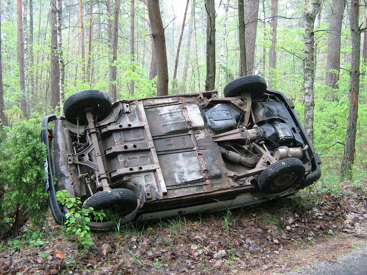
FIG 01. FLOORPAN FORMING CHASIS
It serves as the foundation of most of the structural and mechanical components of a unibody automobile to which the powertrain, suspension system, and other parts are attached.
The below image shows the trunk floor panel of KIA automobile product. In this way the design varies from company to company.
FIG 02. FLOORPANEL OF KIA
MATERIALS UTILIZED:
The materials utilized for constructing trunk floor panel are mainly weight reduction concentration .i,e composites. For an instance in Hyundai CRETA model, thermoplastic honeycomb core technology has been used. IT was done by a tier 1 automotive supplier EconCore, Specialist in lightweight thermoplastic honeycomb core technology, and DPA Moldados.The thermoplastic composite, combining a sandwich panel of polypropylene (PP) honeycomb and glass mat thermoplastic (GMT) composite skin which reduces the weight by 20%. The technology developed was patented & is produced continuously while direct lamination of the sandwich skin layers is most often in-line integrated in the highly automated process.
EDGES OF A MODEL:
The perimeter of a surface is defined by edges. There are four types of surface edges:
•Free edges:
Free edges are colored in red and they appear between two adjacent surfaces which means, the gap between two surfaces need to be fixed.
•Shared edges:
Shared edges appear in green color. When the edge between two surfaces is a shared edge, there is no gap or overlap between the two surfaces, means they are continuous.
•Suppressed edges:
Suppressed edges are colored blue. Like a shared edge, a suppressed edge indicates geometric continuity between two surfaces.
•Non-manifold edges:
Non-manifold edges are colored yellow and they basically occur at "T" intersections between surfaces or when 2 or more duplicate surfaces exist.
QUALITY CRITERIA:
WRAP ANGLE:
Warpage is the amount by which an element (or in the case of solid elements, an element face) deviates from being planar. Since three points define a plane, this check only applies to quads. The quad is divided into two trias along its diagonal, and the angle between the trias’ normals is measured.
FIG 03. WARP ANGLE REPRESENTATION
ASPECT RATIO:
The aspect ratio of 2D element is defined as the ratio of its shortest edge length to its longest edge length. A square has the aspect ratio of 1 since its sides have the same length. Aspect ratio < 5 is highly recommended.
Aspect ratio = Max edge length/Min edge length.
FIG 04. ASPECT RATIO IN QUAD FIG 05. ASPECT RATIO IN TRIA
SKEWNESS:
It defines how element deviate from the ideal element shape. The skew angle represents the absolute value of the difference between the angle and 90 degree. Skewness< 45 degree is highly recommended.
Skewness=90 degree-smallest angle.
NOTE: In skewness smallest angle causes the largest skewness.
FIG 06. SKEWNESS IN TRIA FIG 07. SKEWNESS IN QUAD
JACOBIAN:
The Jacobian ratio is found by the ratio of the maximum and minimum determinant value. The Jacobian calculation is done at the integration points of elements commonly known as Gauss Point. At each intergration point, Jacobian Determinant is calculated. It just coordinates the transformation. For 3D cube, Jacobian is 1. If we disort the cube by applying pressure at one of the vertex, Jacobian < 1. Jacobian is recommended to be > 0.6.
PROCEDURE:
MIDSURFACE EXTRACTION:
Unlike plastic components, the method used to extract midsurface for the floor panel surface here is auto midsurface.
STEP 1) Import the model, open the side door model from your library & select import button at the bottom.
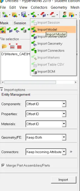
FIG 08. IMPORTING MODEL
STEP 2) Select midsurface option from geom panel.

FIG 09. GEOM PANEL REPRESENTATION
STEP 3) Right click in the surfs button and select displayed option so that entire surface of the panel will selected. After that simply hit extarct button.

FIG 10. MIDSURFACE PANEL REPRESENTATION

FIG 11. MIDSURFACE PANEL REPRESENTATION
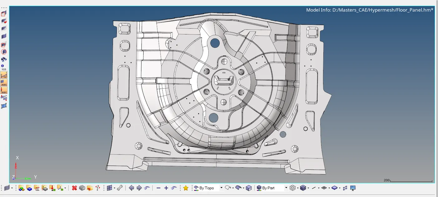
FIG 12. SELECTION OF PANEL SURFACE REPRESENTATION
STEP 4) The below image represents the midsurface generated (red surface) for the panel surface.
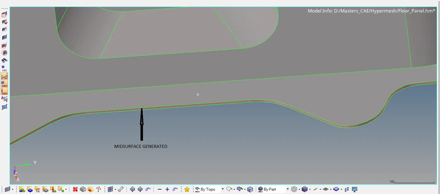
FIG 13. GENERATED MIDSURFACE REPRESENTATION
TOPOOGY CLEANING (or) GEOMETRY CLEAN UP:
After extracting midsurface of the floor panel the next process is to clean the geometry for a perfect mesh.
NECESSITY:
While creating midsurfaces in hypermesh, sometimes for complex geometry there may be geometric errors and discontiunity in surface connection, to fix the continuity issue of the created model & to get proper mesh flow, Geometry clean up is highly necessary. With the geometry cleanup we normally clear only the free and non manifold edges to make them shared edges, that is geometrically continuous.
TOOLS UTILIZED:
1) split surf-node
2) split surf-line
3) toggle edge
4) unplit surf
5) add/remove points
6) release points
7) trim with surfs/plane
8) trim with lines
STEP 1) After creating midsurface of floor panel, work on the small small issue like missing surface capturing from the parent component to make them as shared edge.
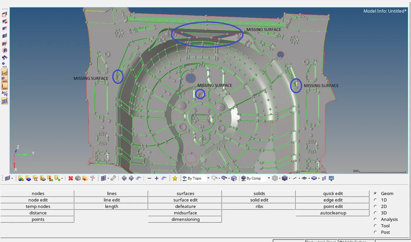
FIG 14. MISSING SURFACE REPRESENTATION
SPLIT SURF-NODE:
STEP 1) Select the node 1 & node 2 of the surface to be seperated.
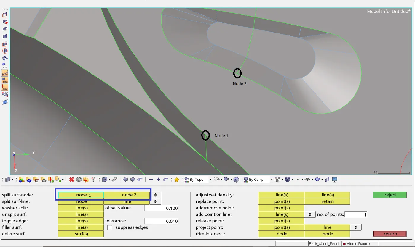
FIG 15. SPLIT SURF-NODE REPRESENTATION
SPLIT SURF-LINE:
STEP 1) Select the node & line of the surface to get seperated.
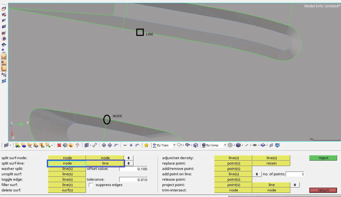
FIG 16. SPLIT SURF-LINE REPRESENTATION
TOGGLE EGDE & UNSPLIT SURF:
STEP 1) Select the line to toggle which disturbs the path for proper mesh flow as shown below.
STEP 2) Also by giving the tolerance value to 0.5 or 1, we can stritch the free edge to shared edge.
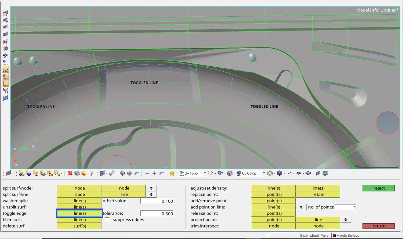
FIG 17. TOGGLE EDGE & UNSPLIT SURF REPRESENTATION
STEP 3) Unslpit surf is used to untrim the seperated surfaces.
ADD/REMOVE POINTS, RELEASE POINTS & REPLACE POINT:
STEP 1) add/remove points is used to add points if we left click on the surface & release points is used to remove the points added if we right click in the mouse.
STEP 2) Replace point is used to replace a particular point.
STEP 3) Select the points highlighted first and retain point second to replace the point.
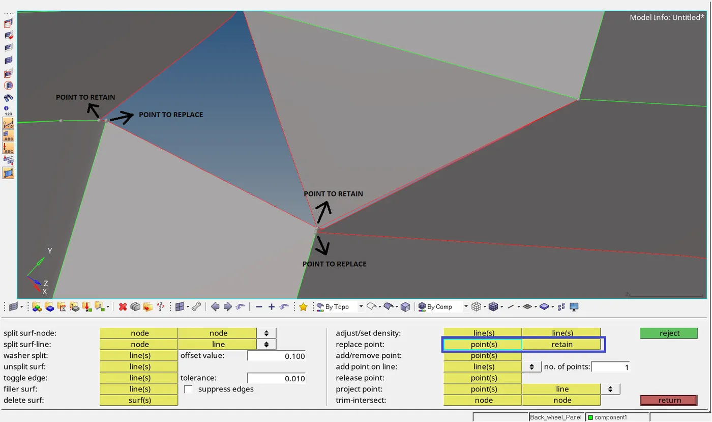
FIG 18. REPLACE POINT OPTION
OFFSET APPLICATION:
In some tricky and complex areas, using tools from quick edit option & creating surfaces doesn't give a way for proper and continuous midsurface. In that scenerio, Offset plays a vital role.
STEP 1) Decide the offset value by measuring the surface ( using distance option or F4 button ) which need to be offsetted. Select OFFSET option from Geom>surface edit panel.
STEP 2) Make sure you select the disjoint effect option.

FIG 19. OFFSET OPTION
STEP 3) Select the surface which has to be offsetted, right click on the surface button & select duplicate option (highlighted).

FIG 20. DUPLICATE SELECTION
STEP 4) Select the current comp option.

FIG 21. CURRENT COMP SELECTION
STEP 5) Select the Vector normal option to see the direction of the surface (arrow pointing upwards direction) about to move.
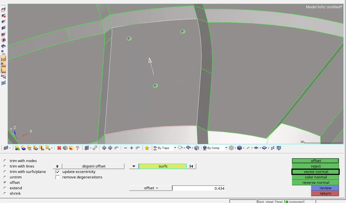
FIG 22. VECTOR NORMAL REPRESENTATION
STEP 6) Reverse normal enables the surface to move downwards. Once the direction is verifed simply click offset button to generate midsurface. Make sure you give the exact offset value in the panel.
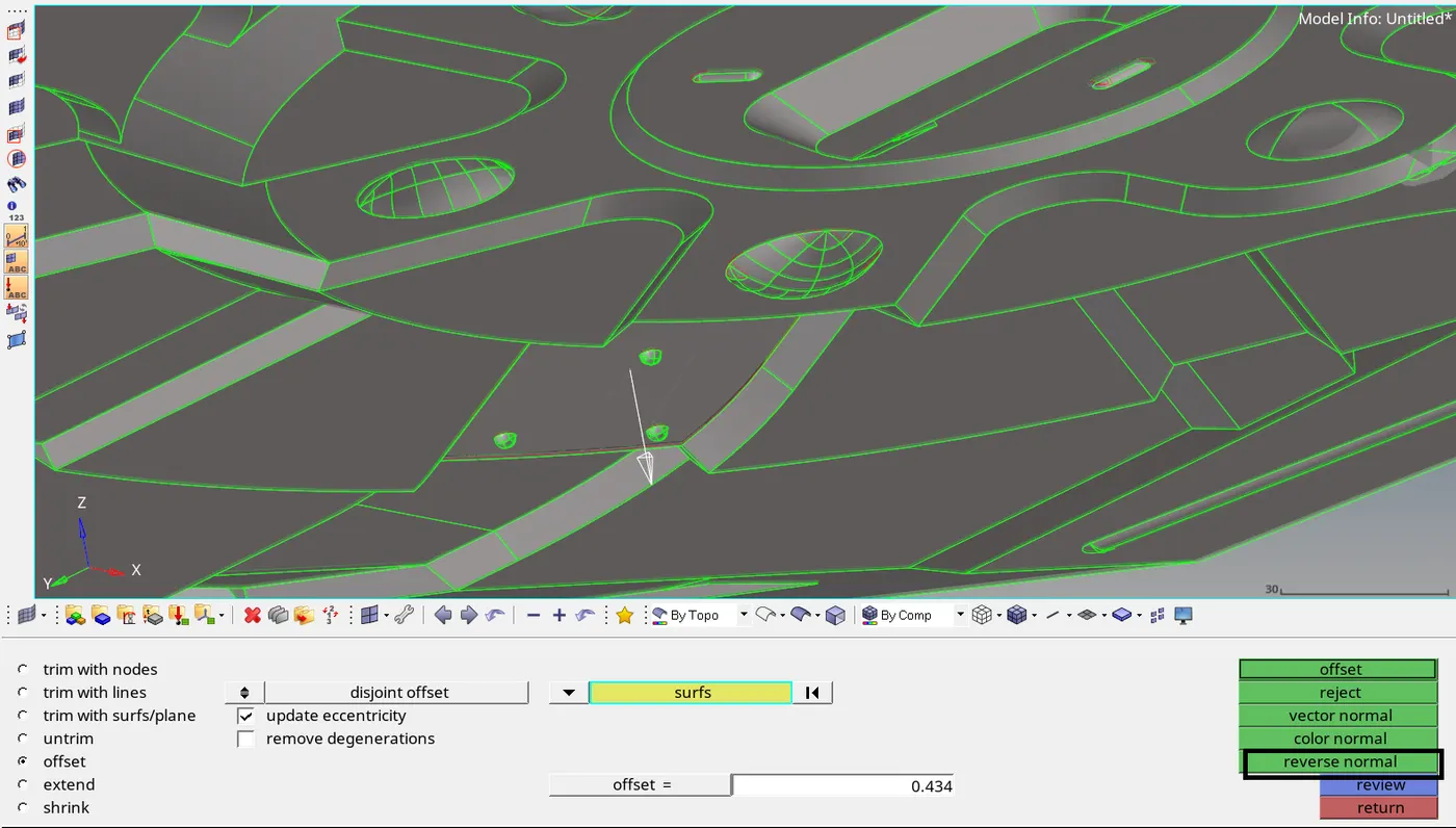
FIG 23. REVERSE NORMAL REPRESENTATION
SURFACE CREATION:
STEP 1) Select surfaces option from geom panel.

FIG 24. GEOM PANEL REPRESENTATION
STEP 2) Select Ruled option from surface panel.
STEP 3) Select the lines in the black shade for the line list 1 and other remaining single line in white shade for the line list 2. Finally select create button to fill the gap by creating a surface.
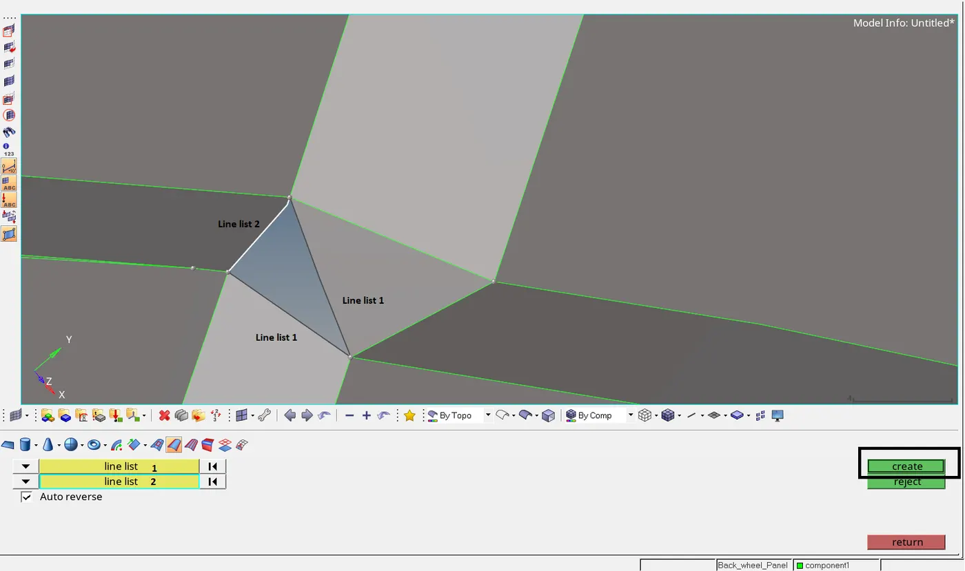
FIG 25. RULED OPTION REPRESENTATION
MESHING:
The next process is to start with meshing of geometry cleaned midsurface with 5 mm of element size.
TOOLS UTILIZED:
1) Automesh
2) Qulity index
3) Smooth
4) Replace
5) Edit element
STEP 1) Go to preference>Criteria file settings.
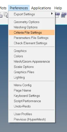
FIG 26. CRITERIA FILE SETTING
STEP 2) Uncheck the checkbox encircled below, input the qulaity criteria & click apply Ok button. We can also load the saved criteria file to avoid filling the quality criteria each and every time while opening the model.
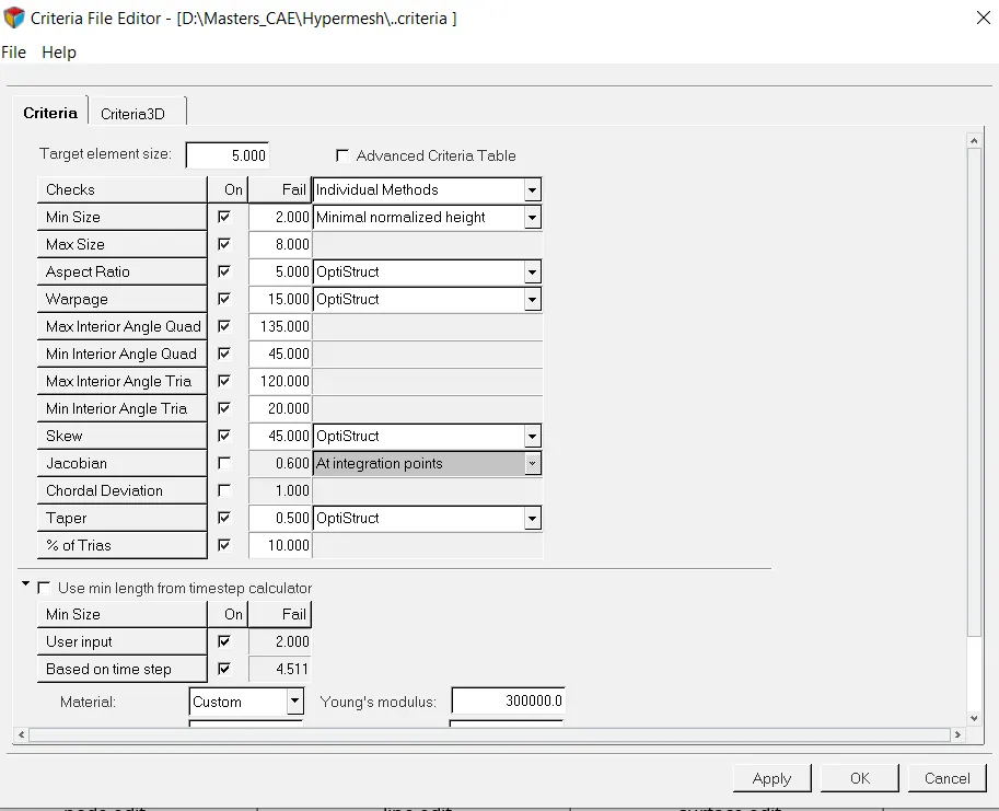
FIG 27. QUALITY CRITERIA
STEP 3) Change the colour mode to "BY Topo" and change the surface visibility to "wireframe Geometry" for the easeness of meshing the surface.

FIG 28. BY TOPO MODE REPRESENTATION

FIG 29. WIREFRAME MODE REPRESENTATION
STEP 4) Start meshing the extracted midsurface surface by surface so that we can maintain proper mesh flow sequence. Use automesh option from 2D panel.
4.1) Make sure you change the mesh type to mixed so that we can avoid rotational quad, which is not advisible.
4.2) To ensure proper mesh flow, tick the align & size.
4.3) Select the surface to be meshed and simply hit the mesh button.

FIG 30. AUTOMESH PANEL REPRESENTATION
STEP 5) The below image represents the meshing of floor panel surface by surface.
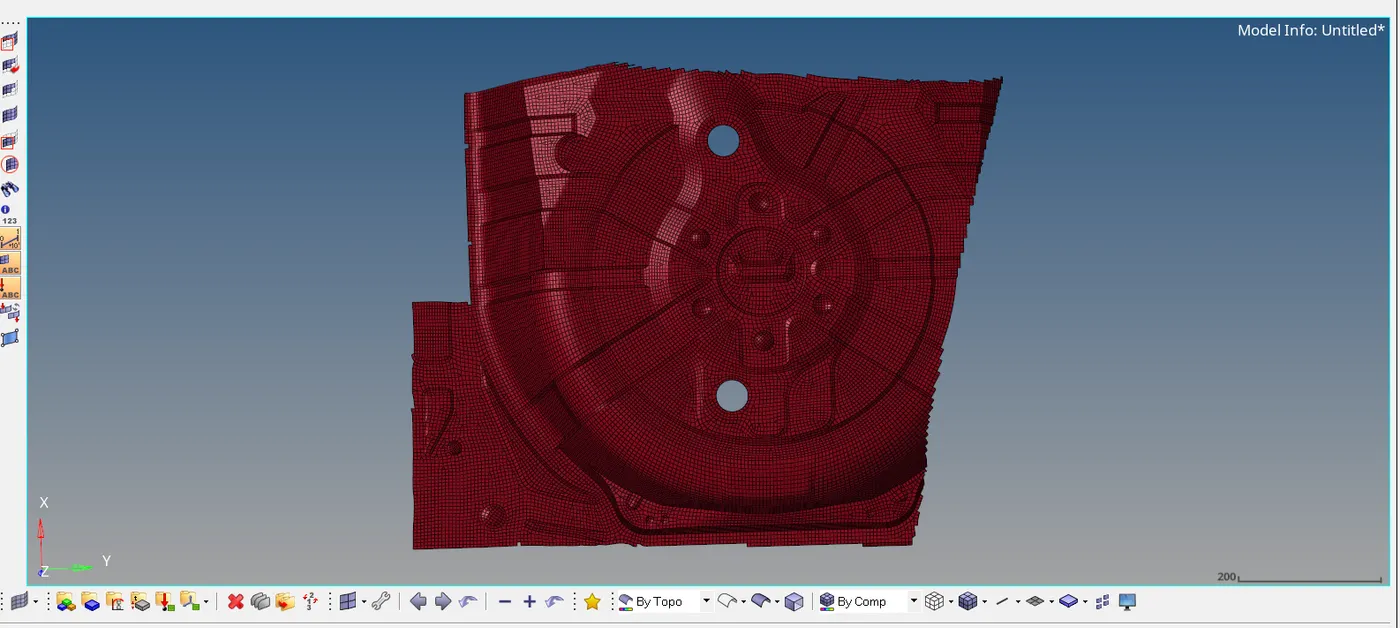
FIG 31. MESHING OF FLOOR PANEL
REASON FOR NOT CAPTURING SMALL HOLES:
Since the circled holes have diameter less than target element size (5 mm), they have been suppressed and not captured.
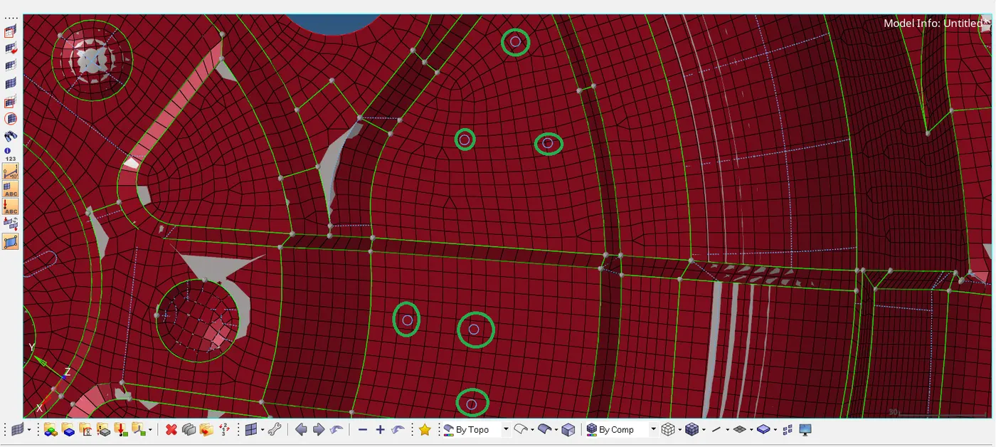
FIG 32. SUPPRESSED HOLE REPRESENTATION
EDIT ELEMENT & REPLACE:
CREATE:
This option is used to create quads or tria elements.

FIG 33. CREATE PANEL REPRESENTATION
COMBINE:
This option is used to combine two tria elements into a quad element.

FIG 34. COMBINE PANEL REPRESENTATION
SPLIT:
This option is used to split a quad element into two tria elements.

FIG 35. SPLIT PANEL REPRESENTATION
REPLACE:
It is used to combine two trias if trias is considered (as per below image) or also used to create two trias if a quad element is considered. Make sure you tick both equivalence & at mid-point option so that the combined element will be at center.
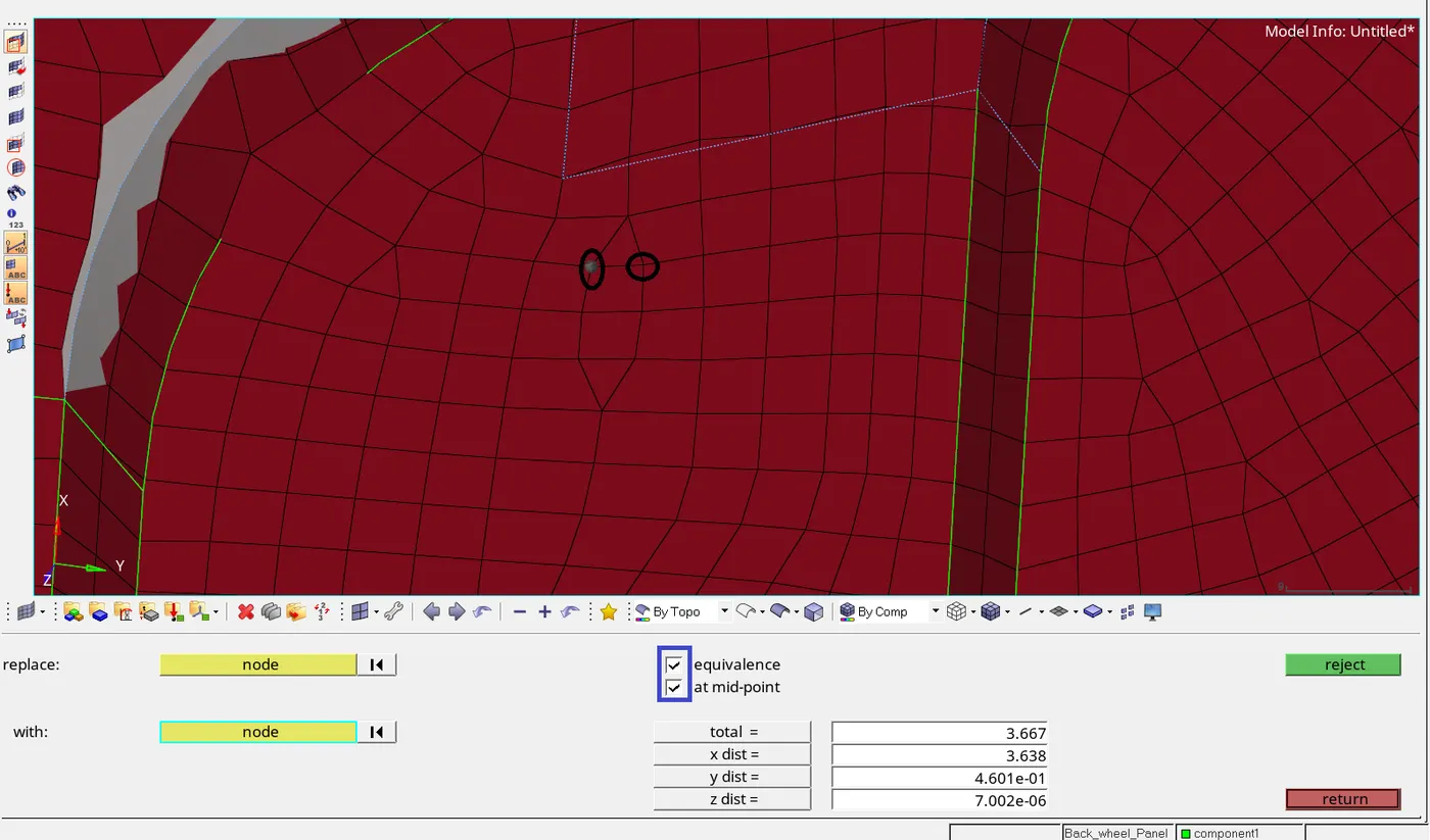
FIG 36. REPLACE PANEL REPRESENTATION
QUALITY CHECK:
Good elemnents gives the way for smooth and accurate results in the analysis. Mesh with bad elements (elements failing for quality), gives lower accurate results and takes long run time. Hence it is mandatory to have a quality check for the meshed elements. Quality criteria like min & max element size, Min & Max tria angle, Min & Max quad angle, Skewness, Taper, Aspect ratio, warpage are mainly given importance.
TRANSLATE:
Translate is ued to fix the warpage of an element.
STEP 1) Go to Tool>check elems or use F10 shortcut key.
1.1) Check the warpage of an element which is failing by left clicking the same element.
1.2) Go to Tool>Translate option.
1.3) Select the node (as circled below) of an element for which warpage has to be fixed, select N1, N2, N3 to define the plane & give magintude value of 0.5.
1.4) Finally use translate+ or translate - button to fix the issue. The issue can be confirmed that it is cleared by repeating STEP 1.
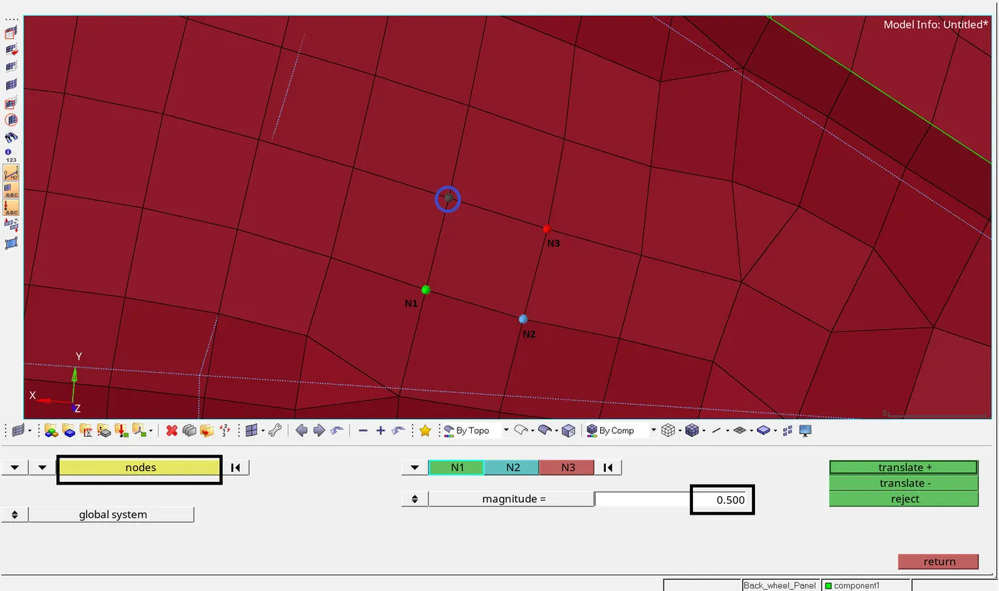
FIG 37. TRANSLATE TOOL REPRESENTATION
MIN ELEM LENGTH:
This issue can be fixed manually by using distance option or using F4 shortcut option.
OPTIMIZATION:
Optimization is used to optimize the element on free edge for a better finish.
SMOOTH:
After working on trias to reduce them, smooth can be used to get regular and proper mesh flow. Trias can be reduced by remeshing the concerned elements.
CHECK FOR FREE EDGE & GAP:
Finally after checking for quality and once it gets passed for every criteria, use Tool>edges or Shift+F3 shortcut to predict the free edges and to eliminate the gap between elements if any.
STEP 1) Select the bunch of elements for which gap presence have to be checked.
1.2) Increase the tolerance value to 0.5 or 1 and simply hit preview equiv.
1.3) If any gap is available it will be highlighted in the elements & click equivalence button.
1.4) Select the entire mesh, by right clicking on the elements and use displaced option
1.5) Select find edges option, & the free edge will be highlighted in red color across its boundary if any.
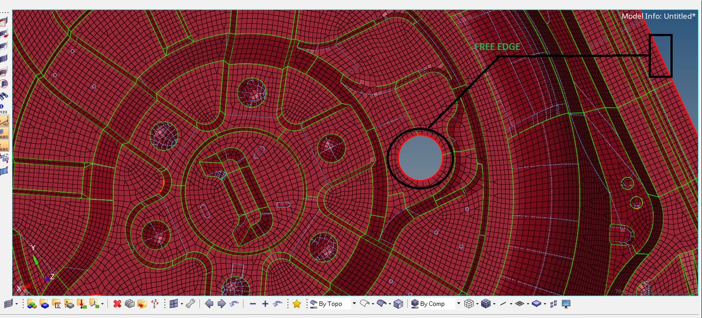
FIG 38. FREE EDGE REPRESENTATION
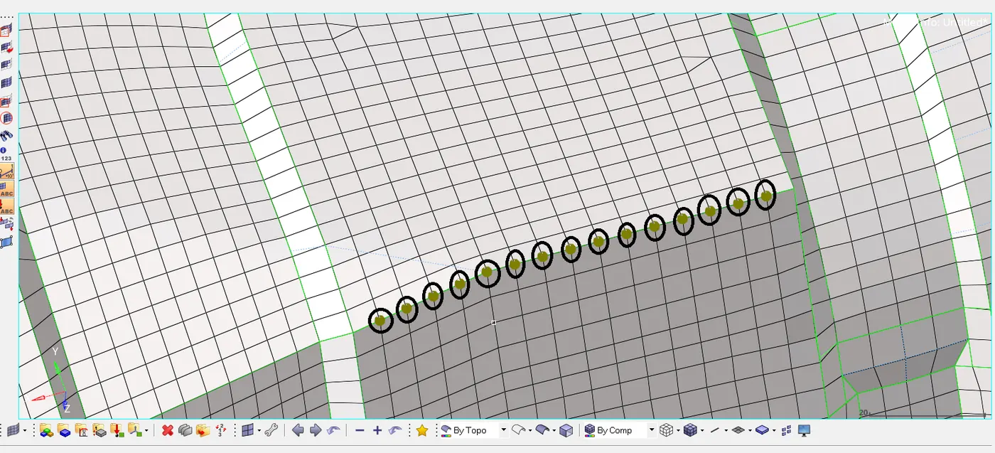
FIG 39. GAP REPRESENTATION
1.6) If free edge is available, then check for equivalence.

FIG 40. CHECK ELEMS REPRESENTATION
THICKNESS ASSIGNATION:
To represent the 2D elements into 3D we have to assign the elements their thickness, taken from the parent geometry.
STEP 1) Right click on the tool bar and create component and property collector for their thickness.
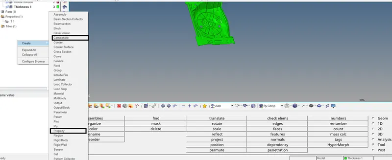
FIG 40.1 THICKNESS ASSIGNATION REPRESENTATION
STEP 2) Give the thickness value as highlighted below and right click the collector named Thickness 1 and assign the T1 property.
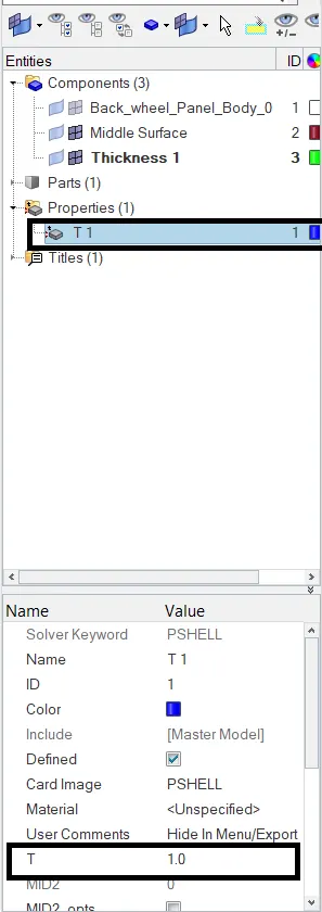
FIG 40.2 THICKNESS ASSIGNATION REPRESENTATION
RESULT & CONCLUSION:
Thus the given floor panel has been meshed successfully with element size 5mm with respect to the quality criteria posted.
MIDSURFACE EXTRACTED:
The below image represents the midsurface of floor panel extracted.
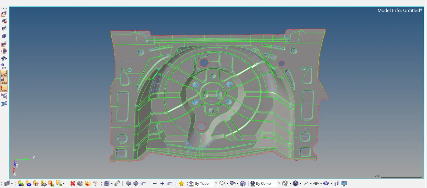
FIG 41. MID SURFACE REPRESENTATION
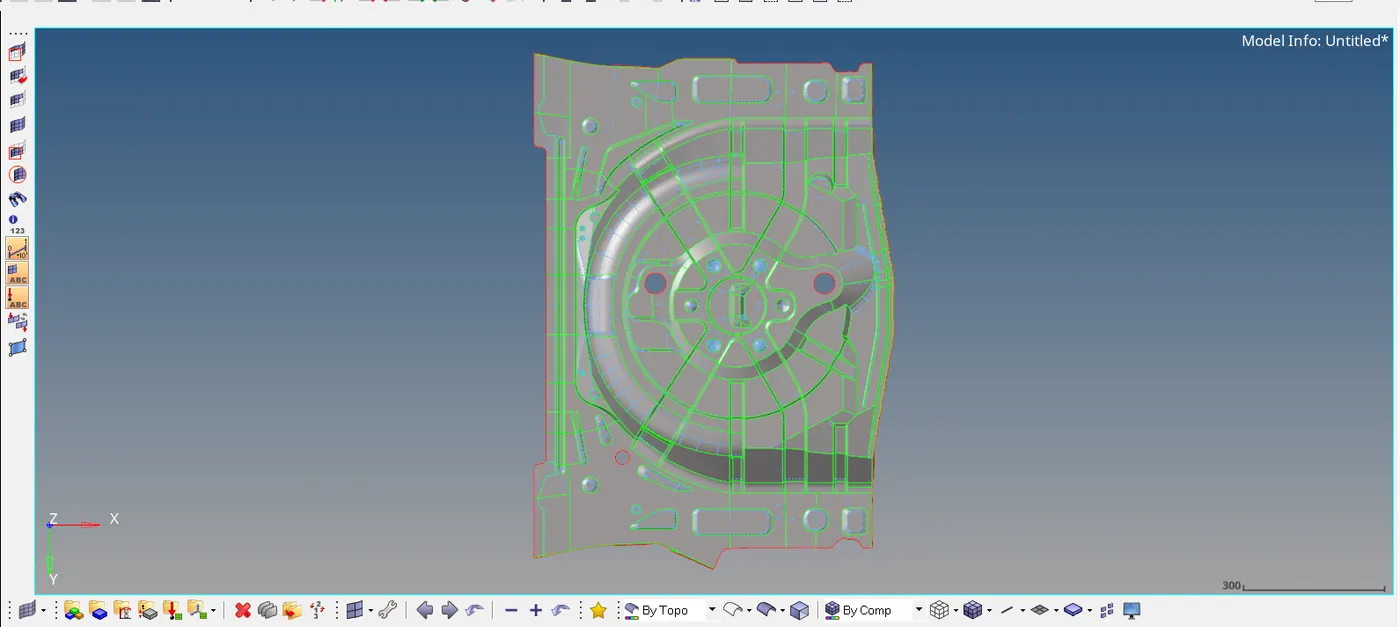
FIG 41.1 MID SURFACE REPRESENTATION
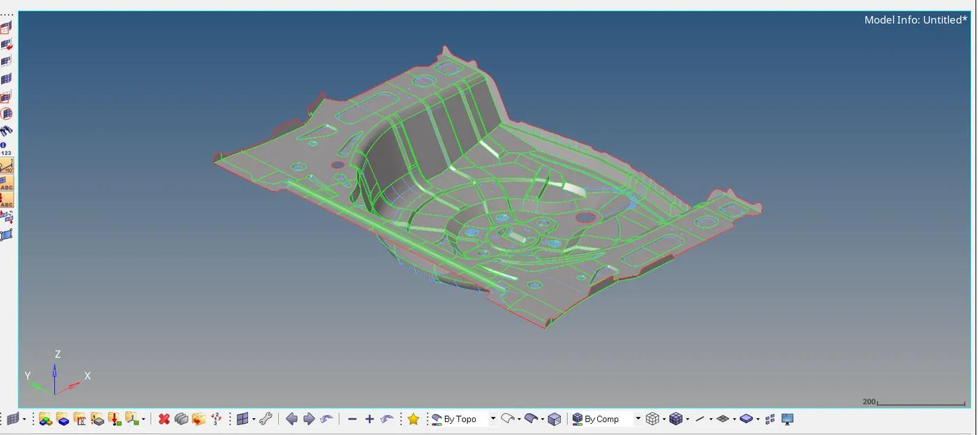
FIG 41.2 MID SURFACE REPRESENTATION
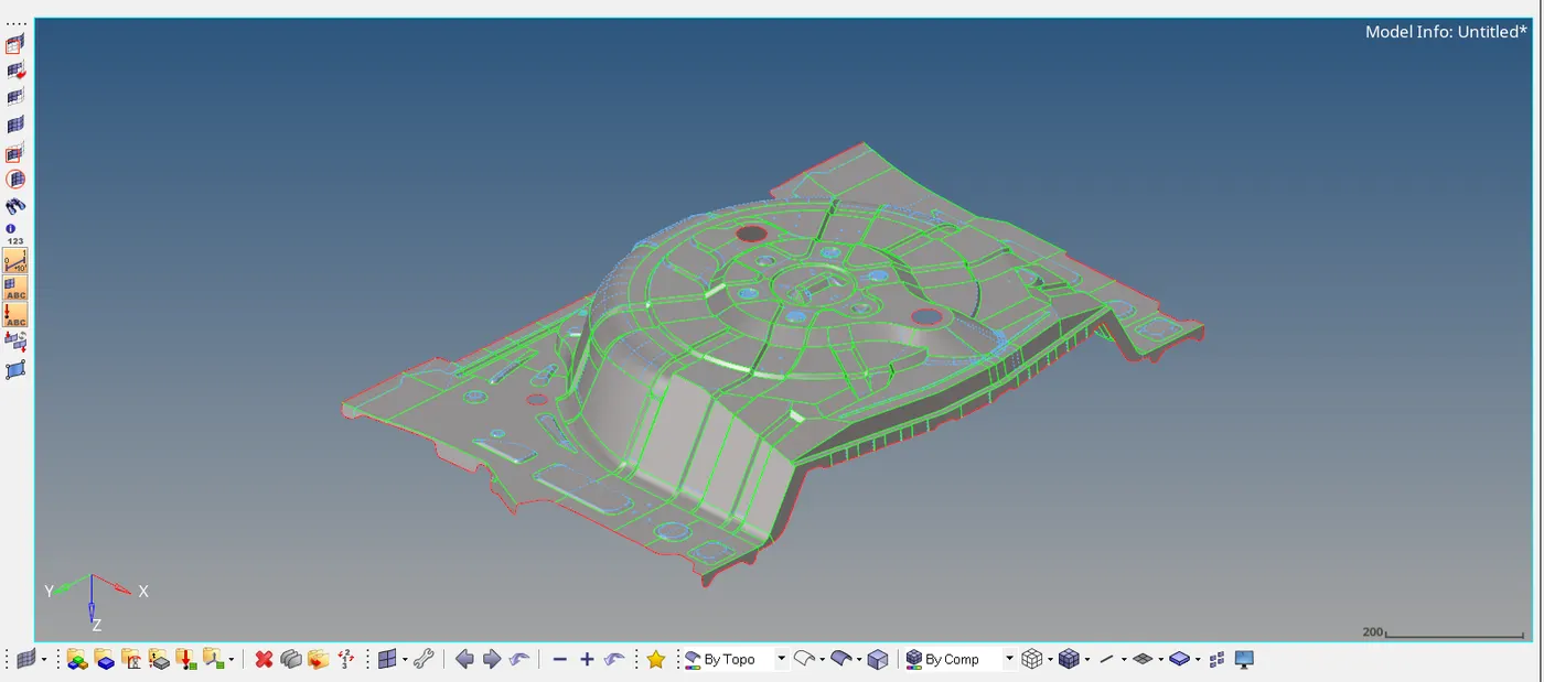
FIG 41.3 MID SURFACE REPRESENTATION
MESHED FLOOR PANEL:
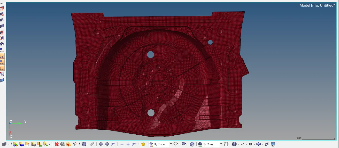
FIG 42. MESH GENERATED REPRESENTATION
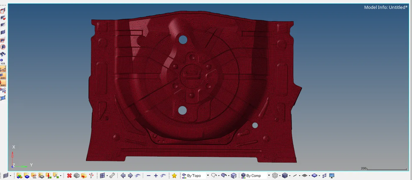
FIG 42.1 MESH GENERATED REPRESENTATION
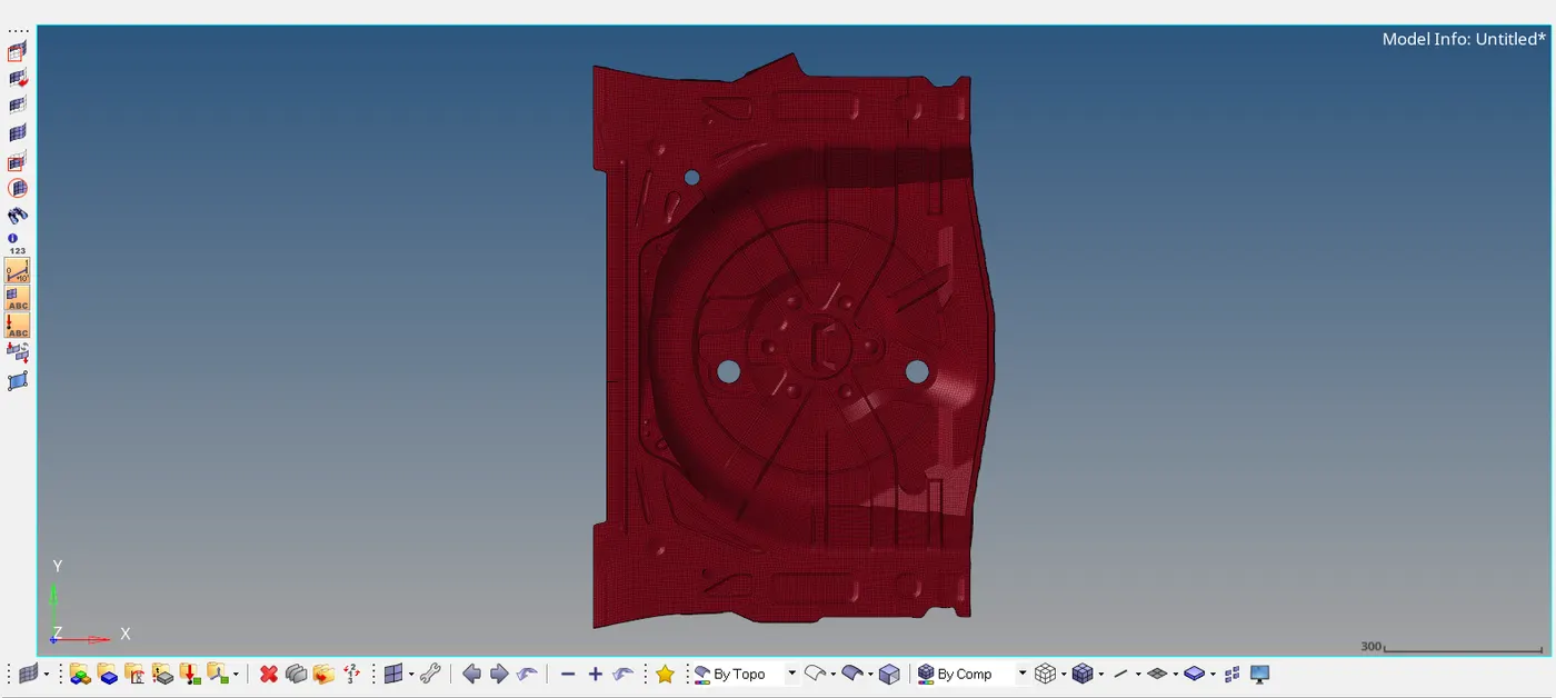
FIG 42.2 MESH GENERATED REPRESENTATION
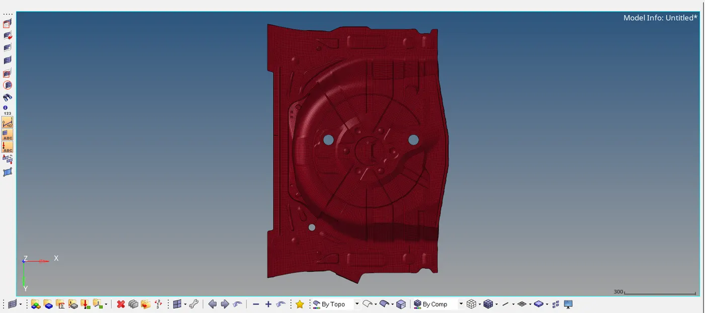
FIG 42.3 MESH GENERATED REPRESENTATION
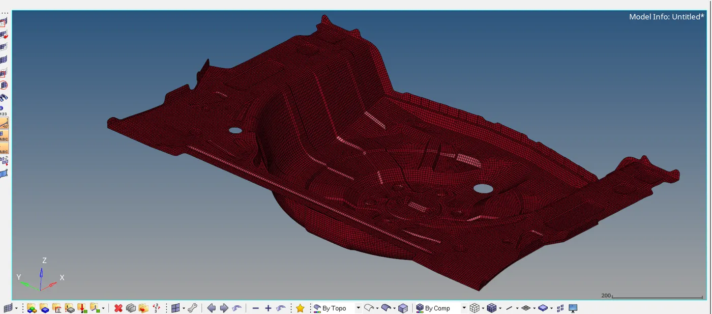
FIG 42.4 MESH GENERATED REPRESENTATION
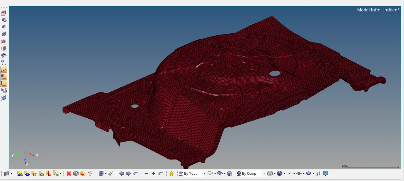
FIG 42.5 MESH GENERATED REPRESENTATION
FLOOR PANEL QUALITY CRITERIA:
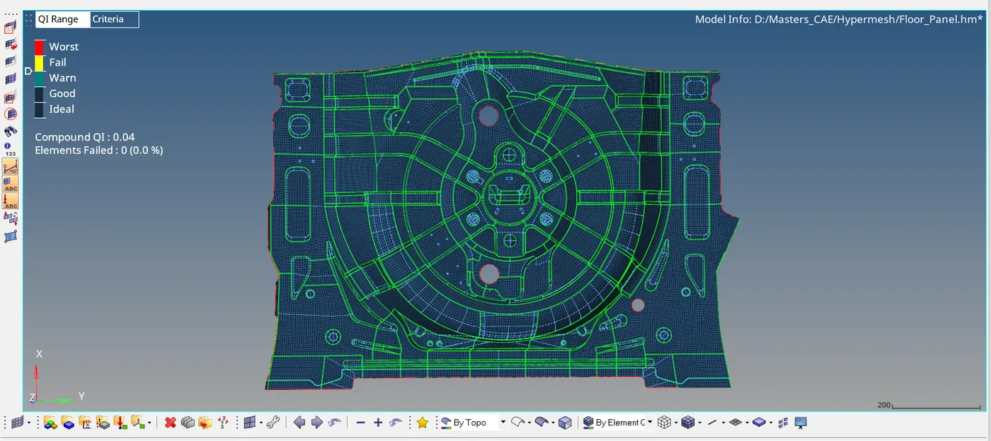
FIG 43 QUALITY CRITERIA REPRESENTATION
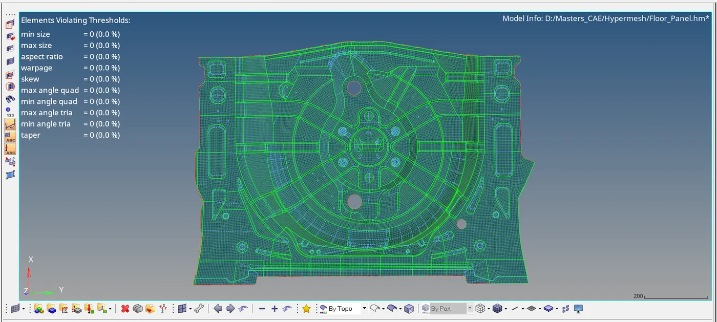
FIG 43.1 QUALITY CRITERIA REPRESENTATION