Project 2
AIM:
To extract the mid surface and do the regular mesh and to achieve the volume mesh in the given suspenion part, and to do the connections required by using the ANSA software.
PROCEDURE:
* The model is to be downloaded and the model is already have done a topology cleanup.
* For confirmation, the model can be achieved with the geometric checks again and 'no error' can appear in the dialog box.
1) MODELLING THE RIM AND TYRE:
Rim:
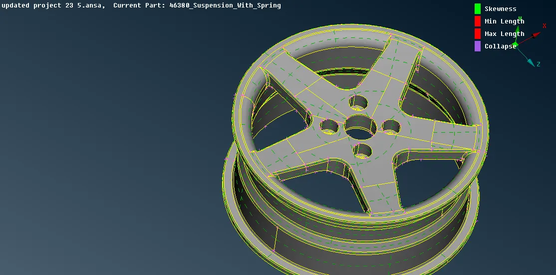
* The rim is already assigned with a separate PID. So, it can be separated by taking this PID alone.
* The rim part will be separately appear, and it is set with the respective quality parameters which is assigned only for rims an wheels.
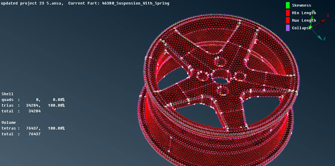
* The mesh parameters are also set and the mesh should be TRIA mode.
* Start the meshing process and make sure that No error should occur.
* Remove the unnecessary construction lines by using CUT and Right Mouse Click.
* Then, Give RECONSTRUCTION for correcting the quality failure. Hence, the quality failure will be reduced as much as possible.
* After the complete mesh of the rim, then go to VOLUME MESH and Define>>Manual/Auto detect and we have to set PID for volume.
* Then it shows UNMESHED. We have to give REMESH option>>TETRA RAPID and so the entire volume will be meshed so far.
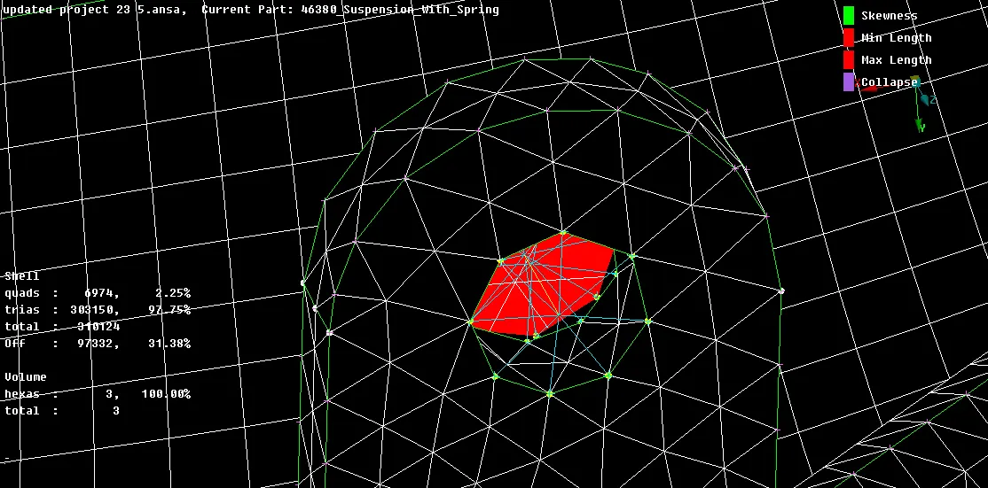
* If any quality failure occur in the volume mesh (only tet collapse), Give FIX QUALITY on the entire volume, and so the mesh won't have any quality criteria failures.
Tyre:
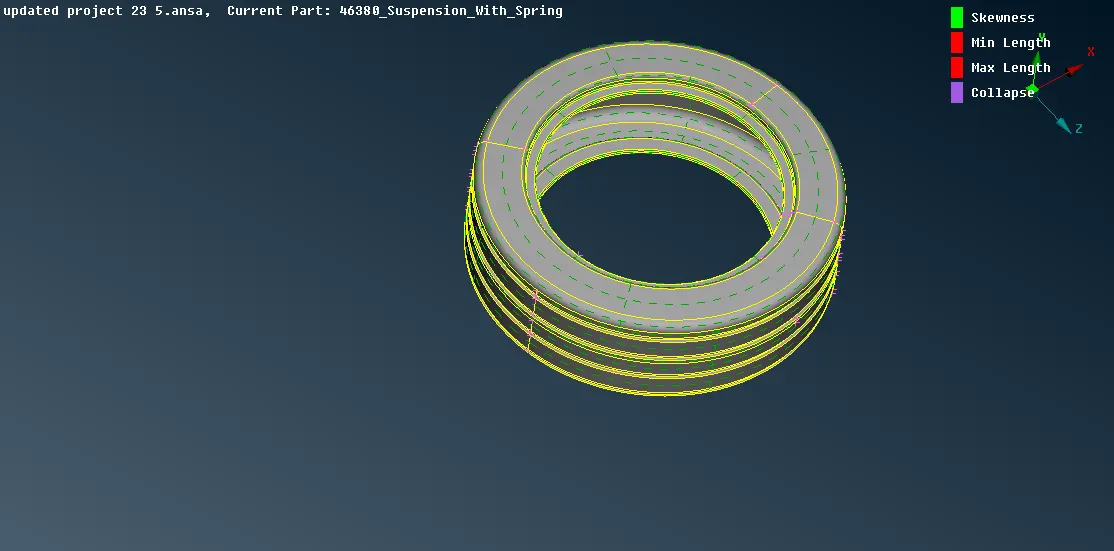
* To do the modelling in the tyre, the tyre is also assigned separate PID
* So, take off the tyre section by using the SHOW ONLY on that PID.
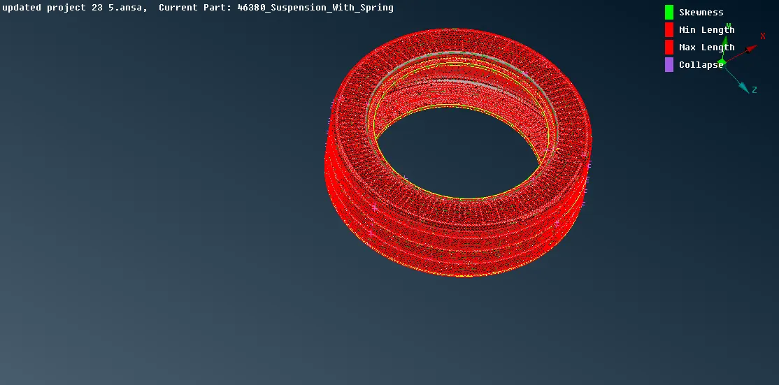
* Repeat the same process as it is done in the modelling of rim.
* Make sure that there should be no off elements, If yes, Give RECONSTRUCT/FIX QUALITY.
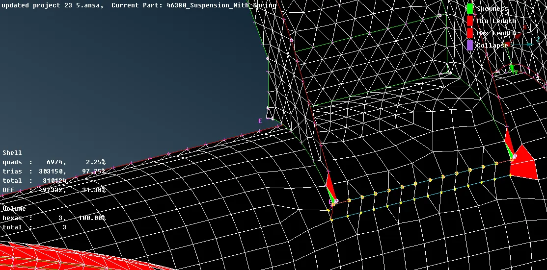
* We can Move The grids if there is MINIMUM/MAXIMUM length criteria.
* Sometimes, SPLIT option also can be used.
SUSPENSION ASSEMBLY:
OTHER PARTS IN SUSPENSION ASSEMBLY:
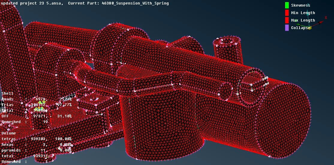
* The modelling of the suspension assembly is quite complicated, because it has to be assigned with various PID's and have to assign with the different quality parameters.
* First of all, We should measure the thickness of the object. Make sure that if the object's thickness is more than 5 mm, go for VOLUME MESH. If not, Go for SURFACE MESH.
* Assign every objects' PID separately for achieving easier way of modelling.
* Give Tria mesh for volumes on all the surfaces which are more than 5 mm on all the parts entirely.
* And so, if the errors are occuring, give RECONSTRUCTION/RESHAPE/FIX QUALITY and then the errors will be rectified.
* Then, in this process of modelling the SUSPENSION ASSEMBLY model, we can go for VOLUME MESHING and select AUTO. Thus, It will detect the solids automatically and so the solid meshed parts are automatically available in the list.
* After getting added in the list, it will show UNMESHED. so, Mesh it everything by giving REMESH>> TETRA RAPID.
* Note that the VOLUME should be arranged in different PID's so that the volume mesh can be easily identified.
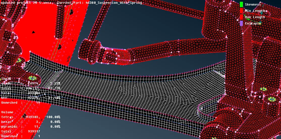
LOWER ARM REGION:
* In some regions, the thickness are less than 5 mm. So, Do the mesh as MIXED, with the same lengths.
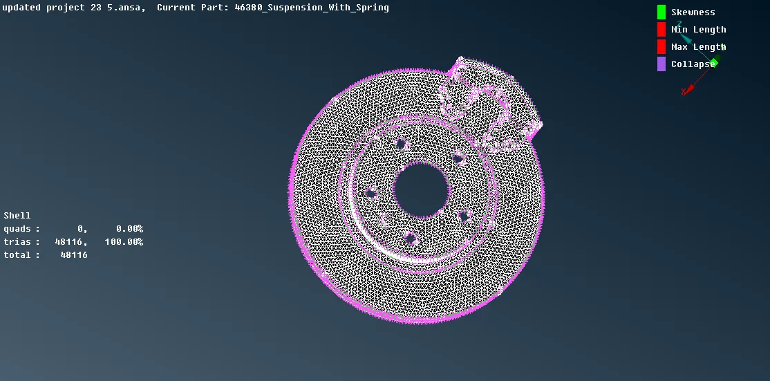
DISC AND CALIPER REGION:
* In the brake region, the parts are to be assigned with the separate PID's for both Disc and Caliper.
* First of all, do the tria mesh in the disc region with the parameter assigned.
* Since the disc has two parts and teeth in between the discs, we have to perform the TRIA MESH one by one.
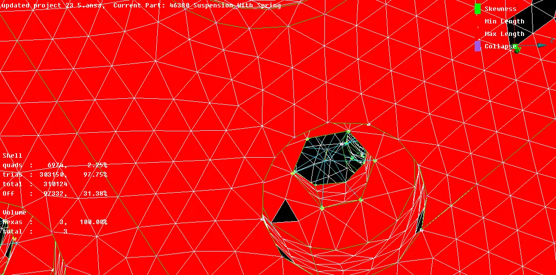
* Then, give the best mesh on all the region on the disc. And give RECONSTRUCT/RESHAPE/FIX QUALITY to remove all the OFF elements. Hence, all of the OFF elements will be removed so on.
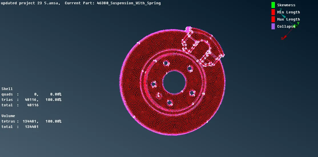
* Then, Go to Volume mesh and Define by using AUTO/MANUAL, and set the Volume PID.
* After setting the PID, The List in the dialog box says UNMESHED. So, Give REMESH and Give TETRA RAPID, and so the volume mesh is generated.
* Repeat the same process in CALIPER region.
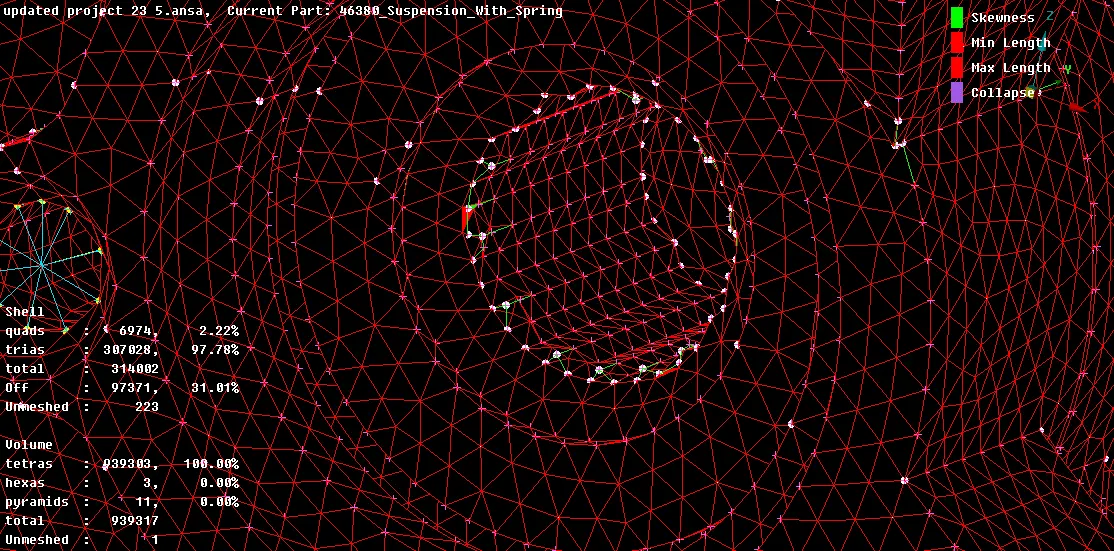
SPRING AND STRUT:
* The spring and strut do have various elements which are both solids and shells.
* On above the spring, Perform the Solid Mesh around the element mentioned above.
* Then, give Volume mesh and define the objects and give REMESH>>TETRA RAPID and thus the volume mesh is Generated.
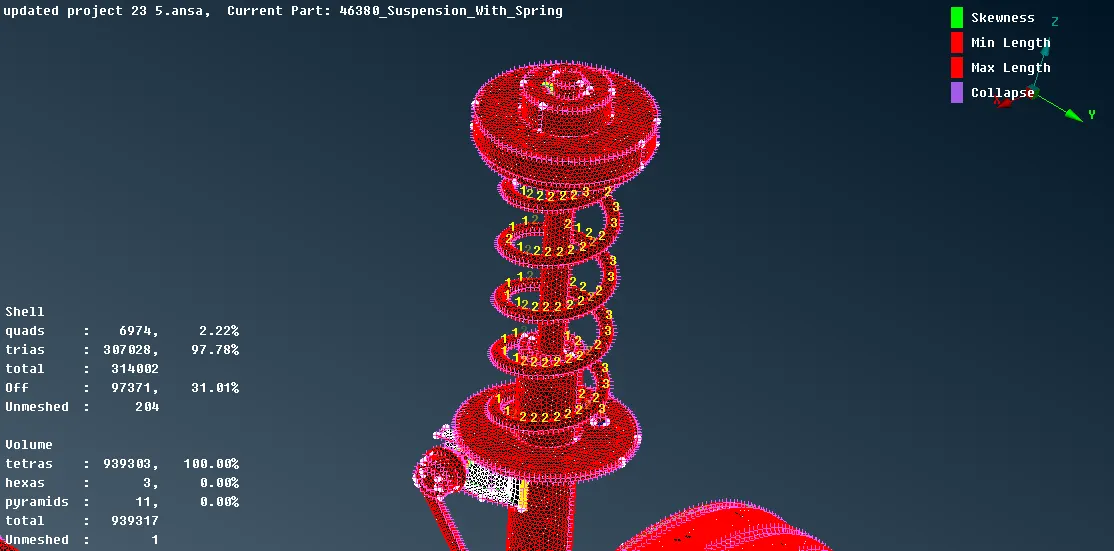
* Repeat the process and give the volume mesh for Springs also.
* Make sure that not the OFF elements should occur in this region.
* For Spring, We have to take CBAR element. To do that,Create the middle curve along the spring and go to NASTRAN mode>>CBAR option and select the orientation and set the PID for the respective CBAR and then give OK. The CBAR element will appear with 3 orientations one-by-one. Before that, we should give the thickness of the spring
* Hence the CBAR along with the volume mesh is taken on the spring.
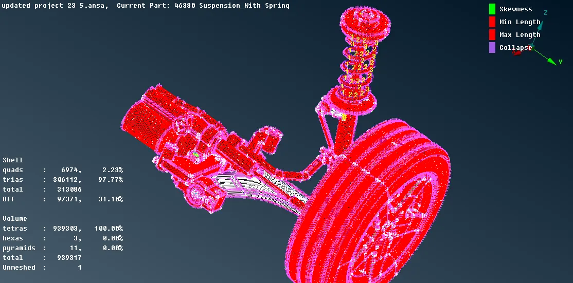
* In another side, we have to take the MID-surface and do the regular mesh for performing the weld.
CONNECTIONS AND WELDING:
* In some areas, we should give connections for BOLT and NUTS, and also rigid connections.
* To give connections, Go to NASTRAN mode>> RBE2>>select the nodes>>Click OK and the connection will be established.
* If the distance is smaller, then you can give total connection in a single master node, and if the distance is larger, you can give as TWO NODAL CONNECTION.
* In some areas The nodal connection can be given as using with nodal points, and give as cluster RBE2.
* In the area where one of the parts in the strut part is taken is to be done with the SEAM WELDING.
* To achieve the SEAM WELDING, we have to create the MIDDLE CURVE and go to CONNECTION MANAGER, andSELECT SELECT THE CURVE and SELECT "OVERLAP-SHELL">> SET PID with respective elements,Weld PID to create the seam weld.
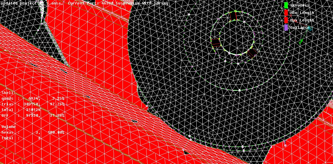
* SPOT WELD also has to be done in the SPRING AND STRUT region. To achieve the SPOT WELDING, we have to create points ON COG, and convert into SPOT POINT.
* Then, Go to CONNECTION MANAGER and select the points>> Select RBE-HEXA-RBE option and set the respective PID's and give APPLY and REALIZE. The spot welds do appear.
LEARNING OUTCOMES:
* Knowing the analysing of the rear suspension model
* Obtaining the knowledge of fully modelling the assembly
* Analysing the welding, connections and the difference between where to do the shell mesh and Solid meshing.
* Knowing the connections to be done
CONCLUSION:
Hence, the modelling of the suspension assembly model is done with the given quality parameters using ANSA software.