Project 2
AIM - To design an interleaving DC/DC converter system for a data centre application with the following specifications:
• Input voltage: 45 – 60 v
• Output voltage: 3 V
• Output current: 100A
Introduction -
Interleaving technique connects converter-converter in parallel to share the power flow between two or moreconversion chains .
It gives a reduction in the size, weight and volume of the inductors and capacitors.
A proper control of the parallel converter will reduce the ripple amount at the input and output of the powerconversion system, which leads to a significant reduction of current and voltage ripples.
Interleaving techniqueis used in some applications due to its advantages regarding filter reduction, dynamic response and powermanagement. Interleaved Buck DC-DC converters have presently acquired a wide importance owing to theirapplication in voltage regulator modules.
Interleaved Buck Converter (IBC) is adopted as a good solution forlow voltage and high current applications .
Interleaved synchronous buck converter is for high-current microprocessors because of the lower input and output current ripple and higher operating frequency of input and output capacitors in comparison with the one-channel solution.
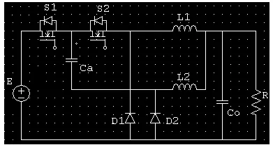
Interleaved Buck Converter for a Non- Linear System is as shown below:-
-----------------------------------------------------------------------------------------------------------------------------
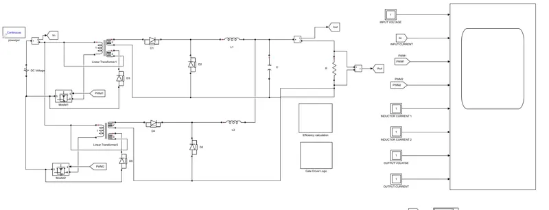
We will design an Isolated Interleaved Forward Buck Converter for this application.
Given Conditions:-
- Input Voltage:- 60 V.
- Output Voltage:- 3 V
- Output Current:- 100 A.
- Efficiency> 85%
Assumption:-
Let the Duty Cycle for the converter be D= 0.5
Switching Frequency (Fs)= 100 kHz.
Calculation Performed:-
For Feed Converter as:-
Vout/ Vin= D* (N2/N1)
3/60 = 0.5 (N2/N1)
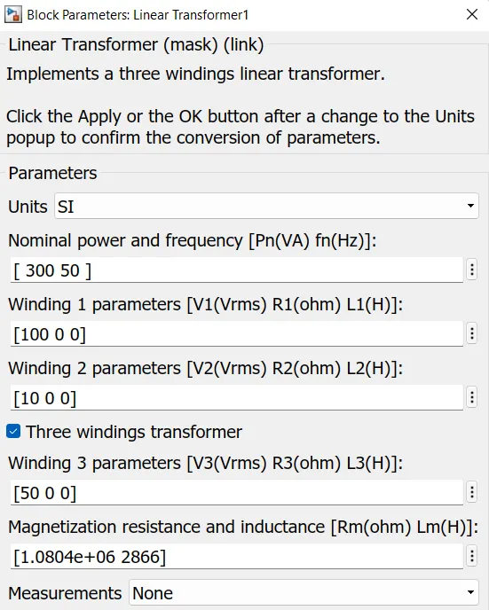
N2/N1 = 1/10
Let N1 = 100 ,
N2 = 10.
We know that
D (1+(N3/N1))<1
0.5 (1+(N3/100))<1
Therfore N3 < 100
Let N3= 50 turns
Applying the following values to the block parameters
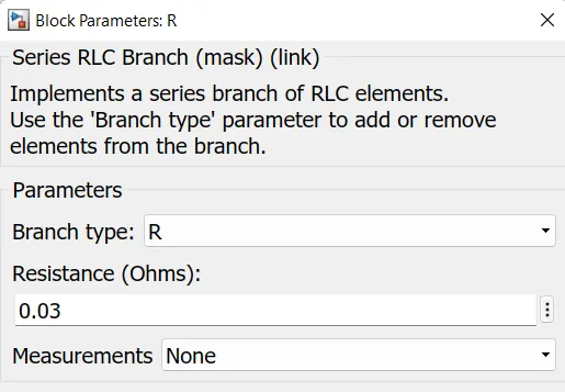
Load Resistance (R) :- Vout/ Iout
R= 3/100 = 0.03 Ω
Po = (Vo^2) / R
Po= 3^2 / 0.03 = 300 Watt.
Total Inductor Current -> IL= IL1 + IL2
Since the current through both the inductor will be equal to output current which is 100 A.
So
IL1+ IL2= 100 A
IL1= IL2 = 50A.
Designing both the inductor for 10% ripple from the average inductor current.
△IL1 = 50 * 0.1 = 5 A.
△IL2 = 50 * 0.1 = 5 A.
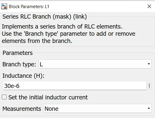
The value of Inductance can be calculated from the below formiula:-
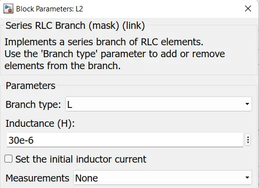
L1 = Vo * (1-D) / (Fs*△IL1)
L1= 30uH = L2
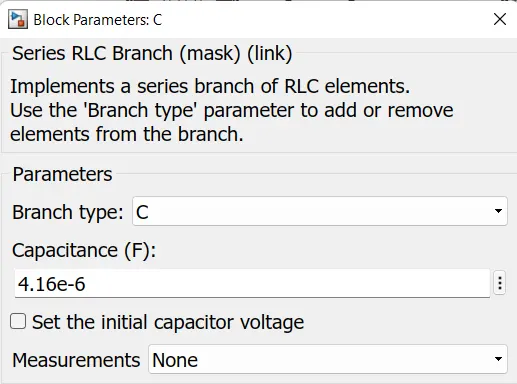
Designing the output capacitor for 1% volatge ripple of the average Capacitor voltage.We have consider both of the capacitor to be of same capacity.
C = (1-D) / (8* L* (Fs^2)* △Vo/Vo)
C= 0.5 / (8* (30 * 10^-6) * (10000 *10^6) *0.01)
C= 4.16 uF.
Simulink Model:-
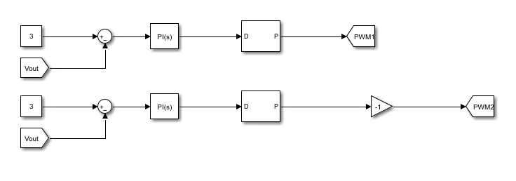
Gate Driver Logic:-
- The gate driver logic is containing the reference output voltage which is 3 V and the output voltage is applied to the negative input of the sum block.
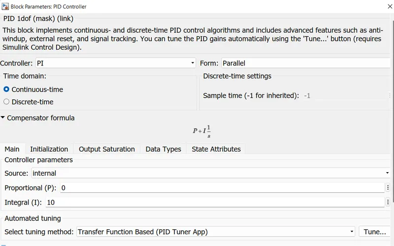
- The error signal is passed through the PI controller and then this actuated signal is passed through the DC- Dc pulse generator having a frequency of 100MHz.
PI Controller:-
DC-DC pulse generator:-
Efficiency Calculation
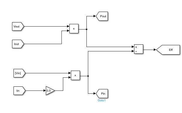
The Output voltage is multiplied with Output current to give Apparent output power and then this Output power is divided by the input powe to get the efficiency.
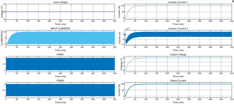
Results:-
zoomed in view
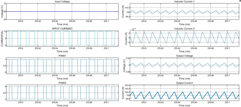
1) Input Voltage and Current - Input Volatge is constant as 60V and the output current .Input current ripple between the value of 0 and 10A. So to find the average input current of we have taken the average of 10 and 0 which is 5 A for simplicity of calculation.
2) Output Voltage and Current - The output current is similar to the output voltage and it reaches the value of 3V at time 0.1 sec.
- Ripple Output voltage is around 2.994 to 3.006 V which is less than 0.4% of the required output average voltage.
- Ripple in Output current is around 99.8 A to 100.2 A which is less than 0.4% of the required output average current.
The Efficiency calculation is shown below:-
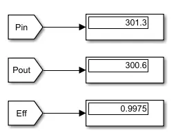
Input power comes to be 301.3 watt and Output power to be 300.6 watt. Therefore the efficiency comes out to be 99.7% which is greater than 90% .