Project 2 - 2D meshing on the instrumental Panel
AIM: To extract the mid surface of the IP Console (Dashboard panel) with certain quality criteria with Proper mesh flow.
OBJECTIVE:
The main objective for the given component is to check for the geometrical errors and mesh with the given element Quality criteria. At the end, the thickness has to be assigned to FE each feature accordingly.
Quality criteria to Follow: -
|
S.No |
Quality Criteria |
Value |
|
1 |
Target/Average length |
4 |
|
2 |
Minimum Length |
2 |
|
3 |
Maximum Length |
6 |
|
4 |
Aspect |
3 |
|
5 |
Warpage |
15 |
|
6 |
Skewness |
45 |
|
7 |
Jacobian |
0.7 |
|
8 |
Minimum Quad Angle |
45 |
|
9 |
Maximum Quad Angle |
135 |
|
10 |
Minimum Tria Angle |
30 |
|
11 |
Maximum Tria Angle |
120 |
|
10 |
Tria Percentage |
15 |
Instrumental Dashboard Panel in Automotive Vehicles
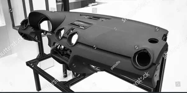
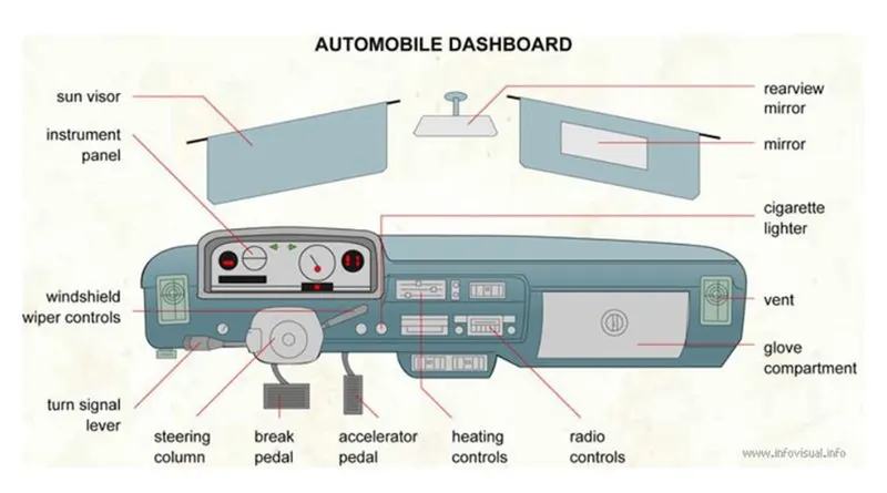
A dashboard (also called dash, instrument panel (IP), or fascia) is a control panel set within the central console of a vehicle or small aircraft. Usually located directly ahead of the driver (or pilot), it displays instrumentation and controls for the vehicle's operation.
Instrument panel (IP), as the largest inner trim parts which directly shown to passengers, have not only beauty and function requirements but also NVH and safety request. The vibration and noise on the dashboard can be directly felt by passengers. Thus, the modal analysis of the instrument panel plays an important role in the NVH character of the whole vehicle.
CAE analysis is a very efficient way to study the NVH character. As it can help shorten the test cycle and reduce development costs, CAE analysis is widely used during automotive development procedures.
Procedure:
The procedure for performing 2-D meshing on the given Instrumental Panel component is as follows
Importing the CAD file in the ANSA interface:
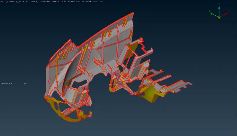
Imported CAD geometry looks as above
Image shows the red lined Those are single CONS it indicates that the geometry is not properly stitched and also number of unchecked faces indicates the same it also shows that there may be some unwanted or distorted or overlapping surfaces may be present in the imported model
In order to stitch the geometry properly we will need to perform TOPO on the given model
For that command is FACES>TOPO in TOPO module
Next step is to perform geometry checks operation onto the model to remove any errors present i.e. unchecked faces, collapsed cons, crack between two faces etc
Geometry is checked using Menu bar > Tools > Checks > Geometry. In the template, all the geometric failures are ticked and the check is executed. The check manager shows all the encountered errors:
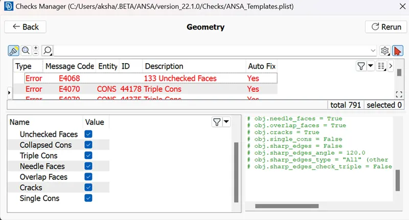
Some of the errors we can auto fix some are to be removed manually. The errors are selected and fixed automatically using right-click > Fix function
And After manually clearing out the remaining geometrical issues, the following result is obtained:
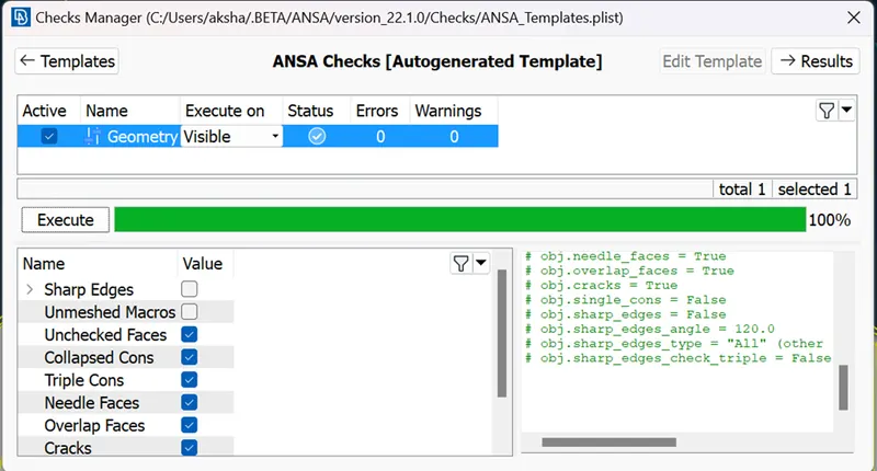
Status shows checked symbol which means there are no outstanding errors in the model
We will measure the thickness of various features present in the geometry and from that we can understand that the component has variable thickness which shows it is a plastic component
We have to provide proper orientation to the given model. Given model should have the correct orientation because the orientation issue will cause the issues when you merge the model with a complete vehicle. It is always preferred to maintain the continuity over the surface either grey or yellow throughout the face.
Extracting Mid-surface:
Mid-surface is the representation of the whole CAD model without the thickness. It captures the whole component with all the features on it in a single layer surface.
The casting method suits best for plastic parts (having variable thickness).
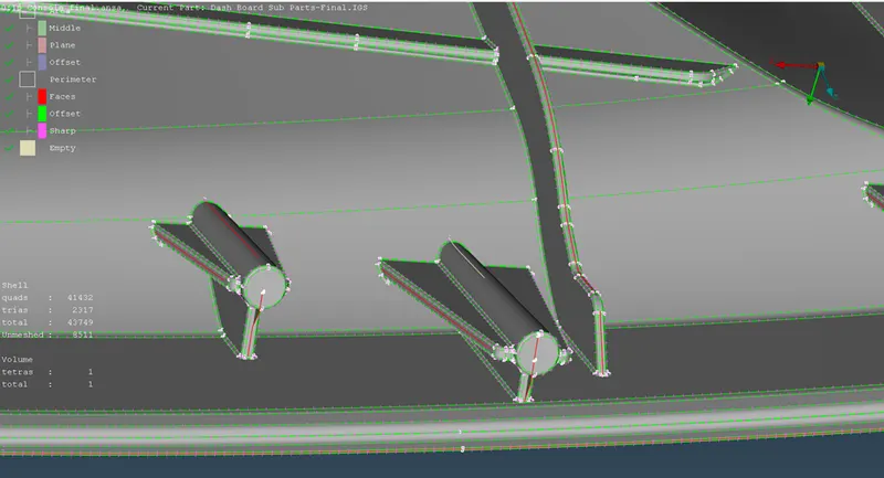
Since the part has complicated geometry (having ribs, fillets and dog houses) Casting method fails to capture the complicated geometry and generates a lot of failed elements.
Main task of ours for this project is to recapture those failed components and properly define them using suitable definitions and recreate the geometry wherever it is distorted due to the casting operation
Following fig shows the FE Model generated after the casting method
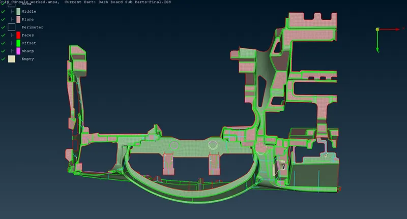
Different colourations in the FE Model represents different types of elements and different definitions that are provided to various features
The Pink colour shows the features which are captured using different planes it also represents Plane definition is provided to them
Similarly green colour is for features captured using middle operation and for middle definitions
Following figure shows The dog house
Recreated dog houses are as follows
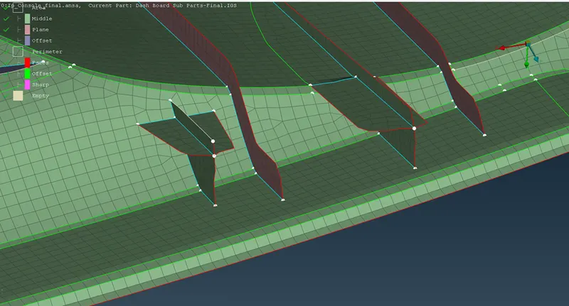
Dog houses are critical area in the component. So, we have to recreate it reference form parent model and work manually, using join, delete disturbs elements, create-curve, curve-middle, feat2curve, cons2curve, and then create new elements using Mesh > elements > new, or Shell mesh > Fill, and after by using the align manager we correct the autogenerated FE.
ALIGN MANAGER:
It is a new feature available to perform the mesh flow which is been aligned to the parent geometry, to extract the exact outer structure i of the Parent geometry.
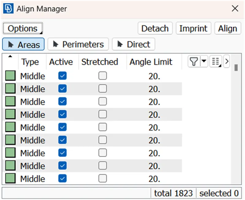
In the align manager there are different tools using which we are able to perform different operations.
With Areas a we can detect different macro areas in order to identify them or to provide different definition to the selected macro area
We have to define perimeters (edges of the features) in the captured FE properly perimeters tools is useful for that
Imprint options is used to imprint the curves or edges from the parent geometry onto the FE model with the view of recreating them for align manager command is FACES>MID-SURFACE>ALLIGN MANAGER in TOPO Model
Also we can use Align Nodes Wizard using Mesh > Grid > Align for getting back Nodes original positions.
we can delete elements and recreate it by Shell Mesh > Fill option, & after that newly created elements are add to the Align Manager by right click on it > new > choose the option accordingly with Middle / Plane / Offset / Cylinder. After adding in Align Manager the elements faces/perimeters get position accordingly to the parent component positions.
Also, one of the most important tools to recapture or to re make the FE is the use of curves
MESH IMPROVEMENT
We have to improve the quality of the mesh that we have got and supposedly to remove or reduce the off elements present different commands which we can use are as follows
smoothing the mesh: (mesh module > shell mesh > smooth).
reconstruct the mesh: (mesh module > shell mesh > improve[reconstruct/reshape/smooth/fix]).
improve the quality of mesh: (mesh module > elements > split/swap/join/stich).
insert or delete hot points: (mesh module > hot points > insert/delete).
to Paste : To paste nodes helps in moving elements backwards: (Mesh > Girds > Paste).
to increase or decrease elements number: (mesh module > perimeters > NUM+/-).
to cut or join the face: (mesh module > macro > cut/join).
ASSIGNING THICKNESS
Assign the proper thickness automatically by using Classic-Mesh > Grids > Thickness > Convert (then select the FE).
The thickness assigned to the model can be viewed using utilities > quality criteria > presentation parameters > Draw shell as solid.
LEARNING OUTCOME
1.Effectively extract Casting Mid-surface /FE.
2.Assigning PID’s automatically in Casting Method.
3.Rearranging construction lines.
4.Geometry Check.
5.Mesh refining.
6.Align Manager uses.
7.Assign Thickness to PIDs.
CONCLUSION:
In complicate models. Casting mid surface /FE & Align Manger effective used and element failure between triple cons having narrow regions cannot be eliminated.
Although Casting process take approx~ a hour time but in this process we don't go for Mid-surface, geometry clean-up, Mesh accordingly. Here we get the FE directly and fix the disturb features and