Project 2 - 2D meshing on the instrumental Panel
AIM: The main aim of this challenge is to mesh the given instrumental panel as per below element quality criteria.
|
S.no |
Element Quality Criteria |
Value |
|
1 |
Target/Average length |
4 |
|
2 |
Minimum Length |
2 |
|
3 |
Maximum Length |
6 |
|
4 |
Aspect |
3 |
|
5 |
Warpage |
15 |
|
6 |
Skewness |
45 |
|
7 |
Jacobian |
0.7 |
|
8 |
Minimum Quad Angle |
45 |
|
9 |
Maximum Quad Angle |
135 |
|
10 |
Minimum Tria Angle |
30 |
|
11 |
Maximum Tria Angle |
120 |
|
12 |
Tria Percentage |
15 |
OBJECTIVE: The objectives of this challenge are as follows:
<!-- [if !supportLists]-->1. <!--[endif]-->To perform geometry clean up and generating mid surface for the given component.
<!-- [if !supportLists]-->2. <!--[endif]-->To mesh the given component with less tria concentration and good mesh flow.
<!-- [if !supportLists]-->3. <!--[endif]-->Finally all the elements should pass for given element quality criteria.
PROCEDURE:
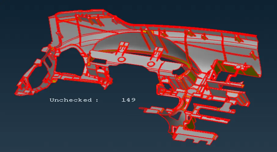
The CAD file in ANSA can be opened by selecting the open option in file tab.
<!-- [if !supportLists]-->2. <!--[endif]--><!-- [if gte vml 1]>
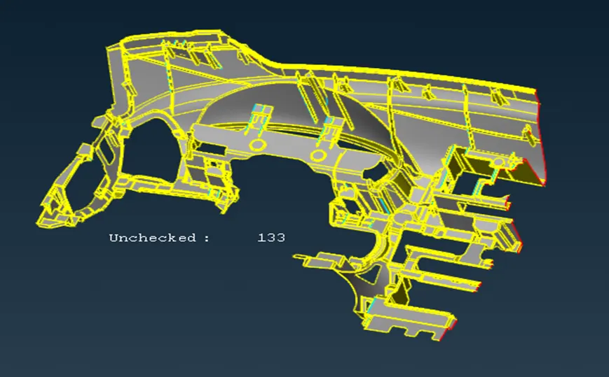
<!-- [if !supportLists]-->3. <!--[endif]-->The edges at the right end of the geometry were not closed and the geometry was having single cons, this error was solved by creating a new surface (TOPOàFACESà NEW) where ever it is required.
<!-- [if !supportLists]-->4. <!--[endif]-->After performing the topo operation, geometry check (TOOLSàCHECKà GEOMETRY) was done in order to remove geometrical errors.
<!-- [if !supportLists]-->5. <!--[endif]--><!-- [if gte vml 1]>
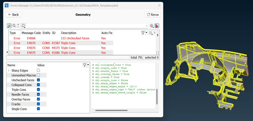
<!-- [if !supportLists]-->6. <!--[endif]-->Some of the errors can be fixed automatically by using fix option and the errors that cannot be fixed automatically needs human attention and those errors should be solved manually.
<!-- [if gte vml 1]>
<!--[endif]--><!-- [if gte vml 1]><![endif]-->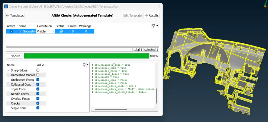
<!-- [if !supportLists]-->7. <!--[endif]-->Once all the errors are rectified, we are good to go for extracting mid surface of the given component.
<!-- [if !supportLists]-->8. <!--[endif]-->Mid surface was extracted by using casting method (TOPO MODULE à FACESà MID SURFACEàCASTING) because the given component is complex and has variable thickness .
<!-- [if !supportLists]-->9. <!--[endif]--><!-- [if gte vml 1]>
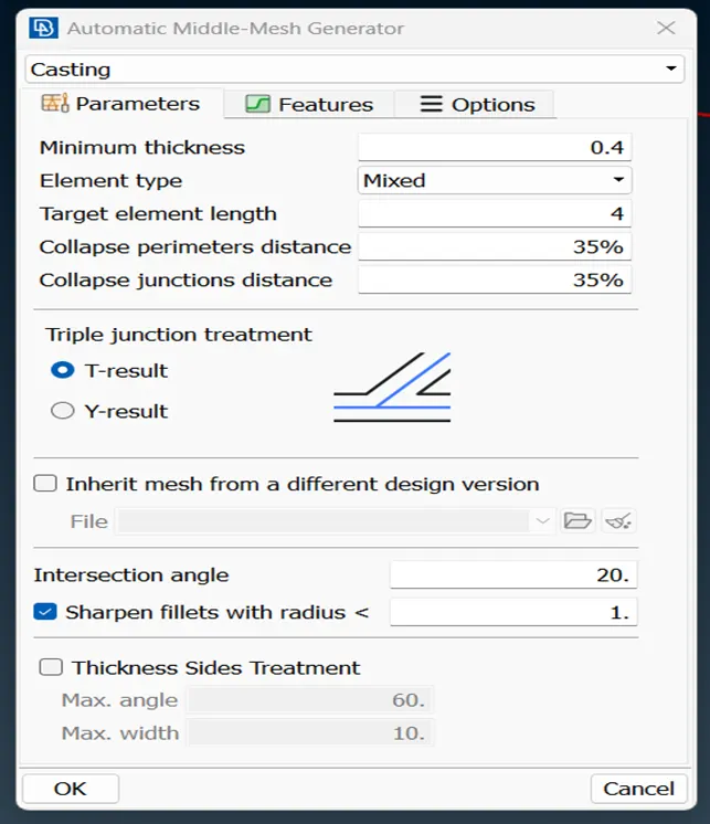
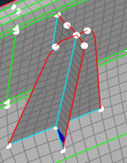
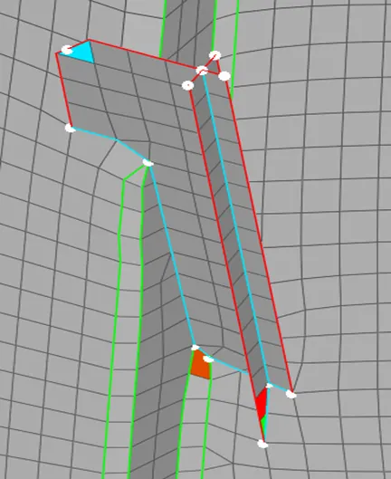
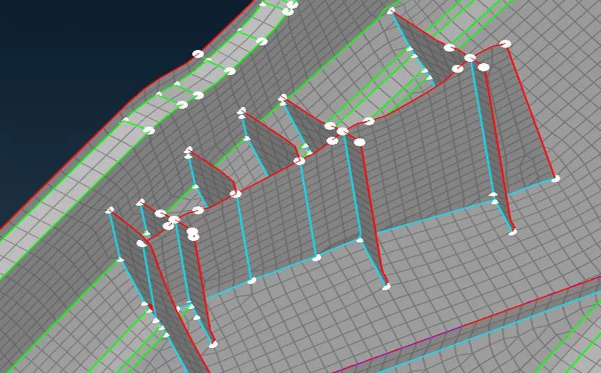
<!-- [if !supportLists]-->10. <!--[endif]-->The critical features such as dog houses were not clearly captured with this technique. Therefore, we must create those dog houses surfaces manually using several options like Curves, Fill and Project etc.
<!-- [if !supportLists]-->11. <!--[endif]-->All the dog houses were captured in the form of cross pattern and were aligned with their parent geometry using align manager option (TOPO MODULE à FACESà MID SURFACEàALIGN MANAGER).
<!-- [if !supportLists]-->12. <!--[endif]--><!-- [if gte vml 1]>
<!-- [if gte vml 1]>
<!--[endif]--><!-- [if gte vml 1]><![endif]-->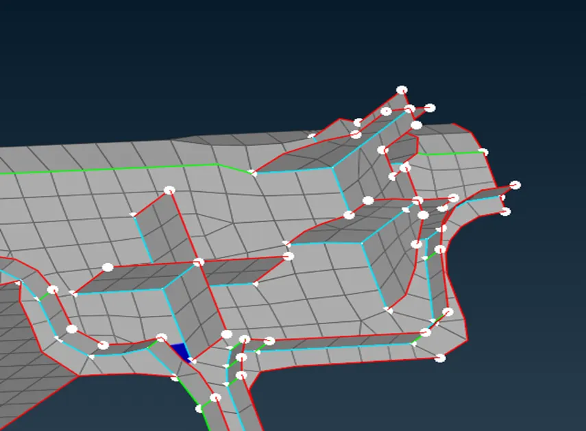
<!-- [if !supportLists]-->13. <!--[endif]--><!-- [if gte vml 1]>
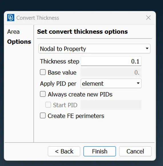
<!-- [if !supportLists]-->14. <!--[endif]-->Finally, automatic thickness can be assigned to the component using thickness command (TOPO MODULE à FACESà MID SURFACEàTHICKNESSà CONVERT) and draw shell as solid was activated in presentation parameters tab .
NOTE:
<!-- [if !supportLists]-->· <!--[endif]-->Element failures near triple cons were left like that.
<!-- [if !supportLists]-->· <!--[endif]-->Some of the critical features were slightly deviated from their parent geometry to avoid elemental failures.
LEARNING OUTCOMES:
<!-- [if !supportLists]-->1. <!--[endif]-->Learnt about geometry clean up and extracting the mid surface using casting option.
<!-- [if !supportLists]-->2. <!--[endif]-->Learnt about how to use align manager for aligning the critical features with the parent geometry.
CONCLUSIONS:
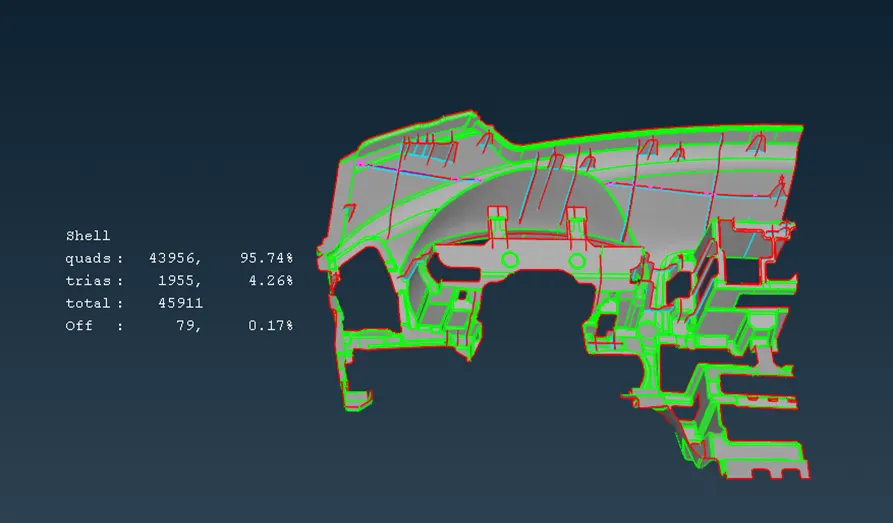
Geometry cleanup, mid surface extraction and meshing of the given component was done successfully. Tria’s concentration was limited to less than 4.5%.
NOTE: CANT ABLE TO UPLOAD THE FILE AS THE FILE SIZE IS TOO LARGE. LINK FOR DOWNLOADING THE FILE: https://drive.google.com/file/d/1Cm_Ymx7VlSiZJJ-7rKbLPKKnFmi2lT6M/view?usp=drive_link