Project 2
* Objective:
The main objective is to create a volume mesh for the given suspension assembly by following all the quality parameters given, and to deploy the connections were ever it is required to rigidise the final assembly.
* Procedure:
- Initially open the file and perform Topo to stitch all the faces properly into a closed structure.
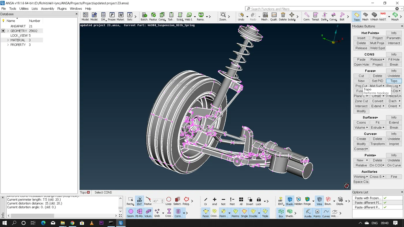
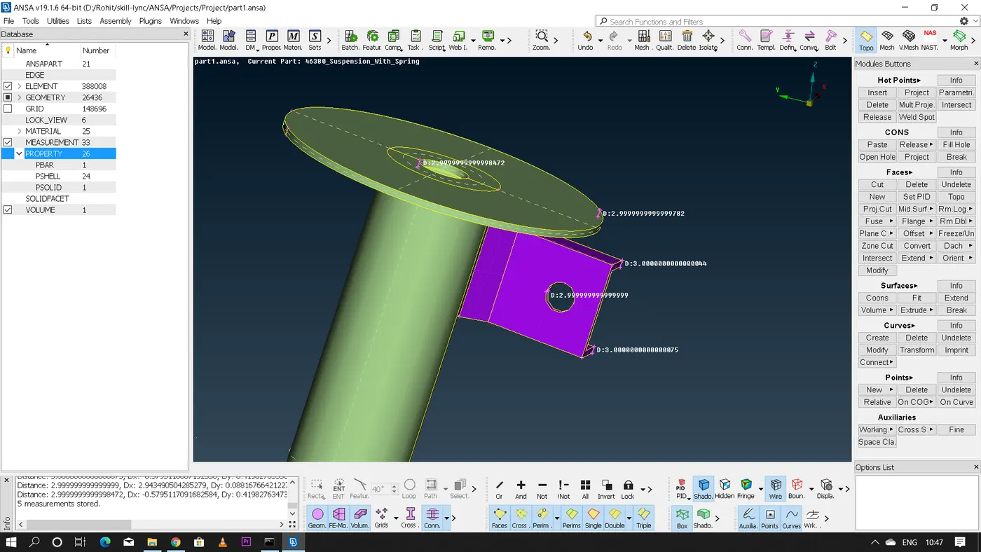
- After doing Topo now we need to perform the gemetry cleanup. Since the given suspension assembly has many subparts included in it with varying geometries it is advised to perform the geometry checks part by part by assigning differernt PID's for each and every feature.
- Geometry check for Rim part:
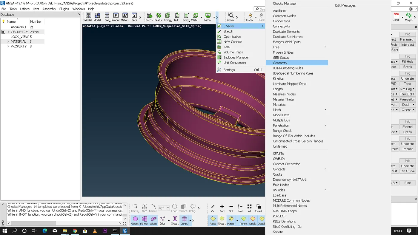
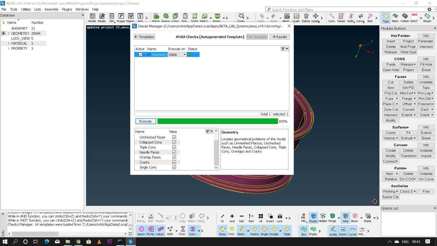
- Similarly geometry check is done for other subparts of the assembly and all the errors has to be fixed by deleting and creating a new surface:
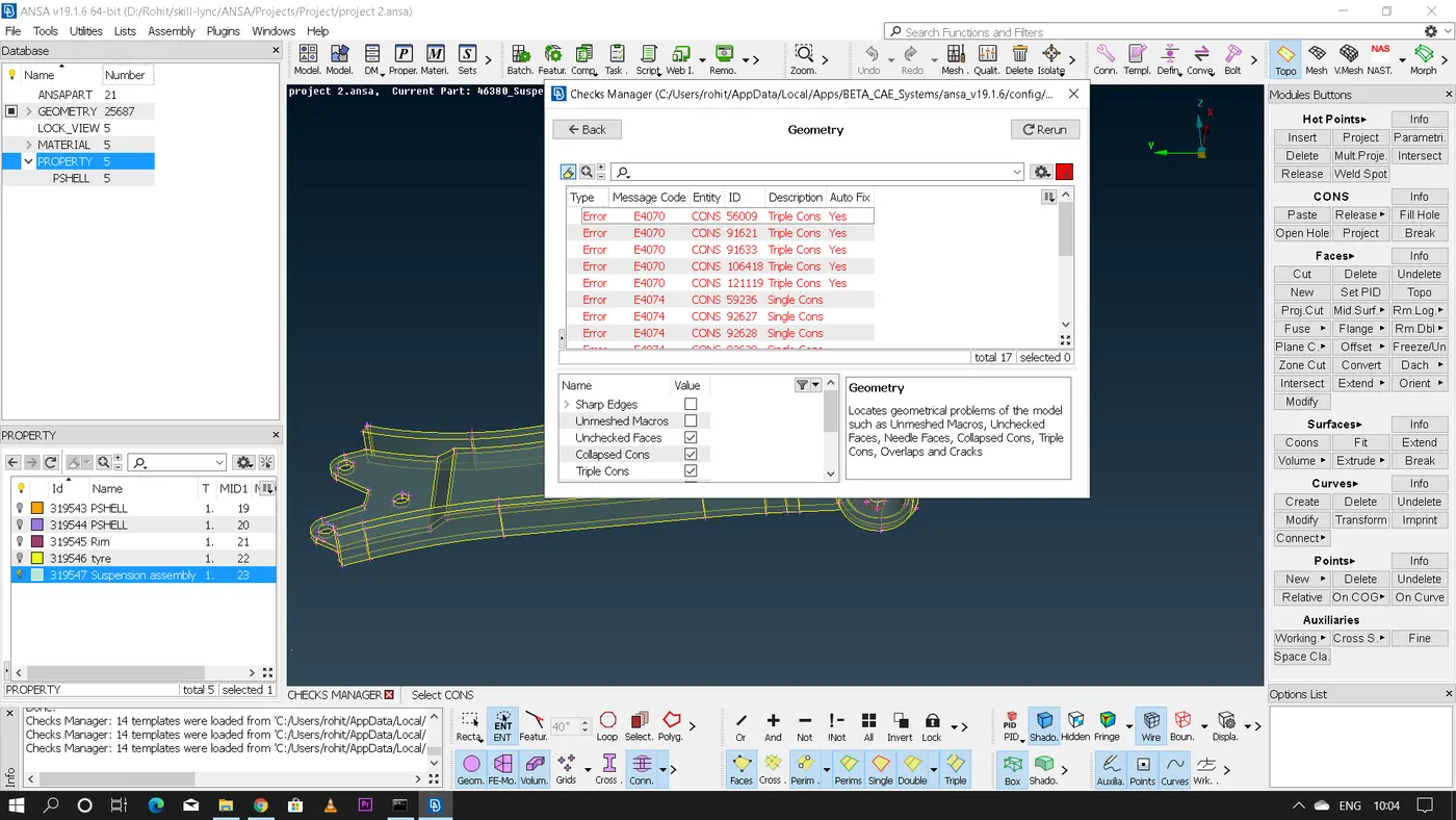
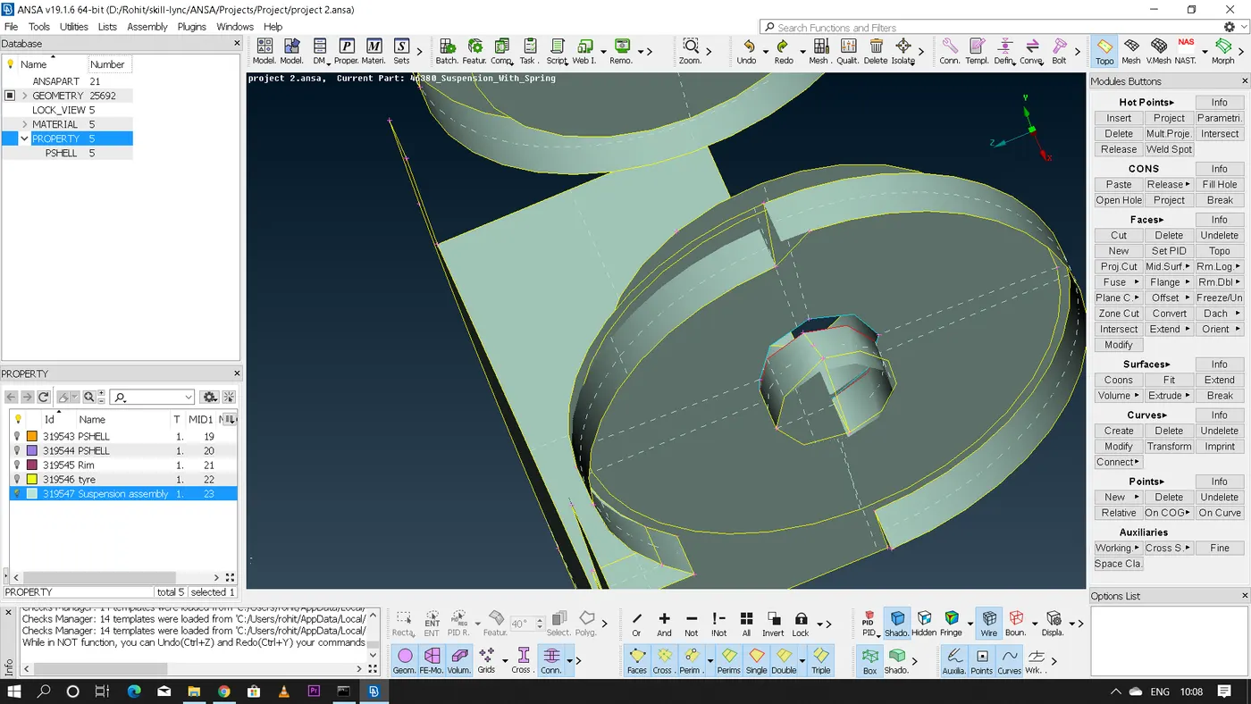
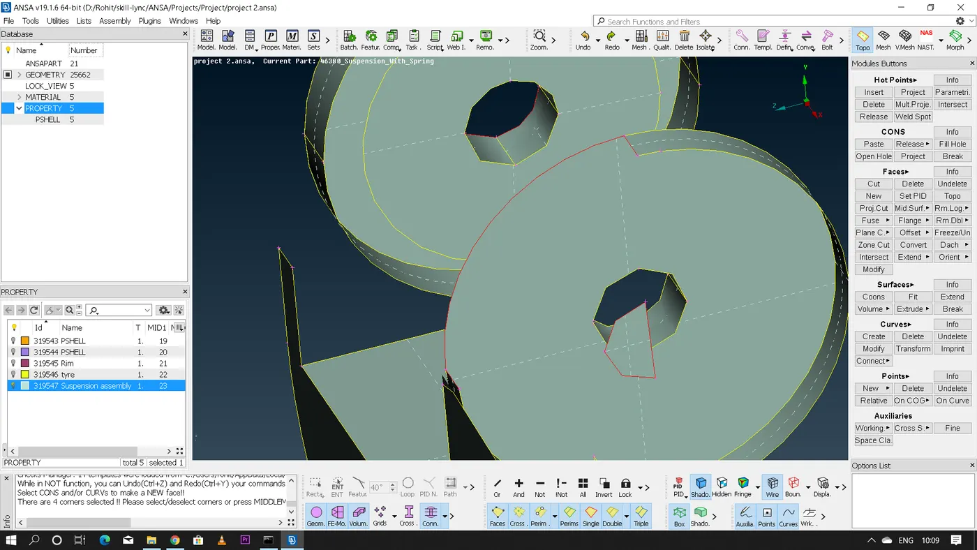
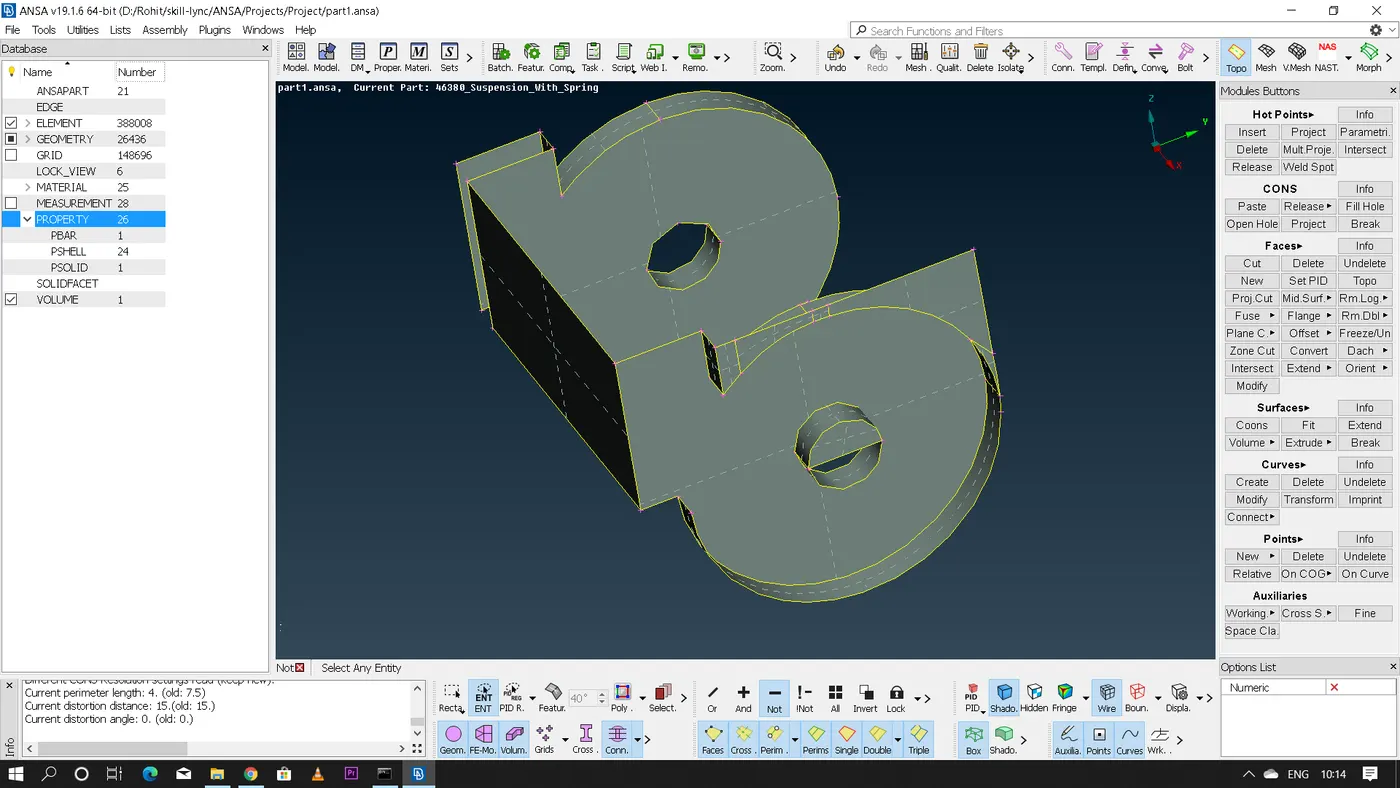
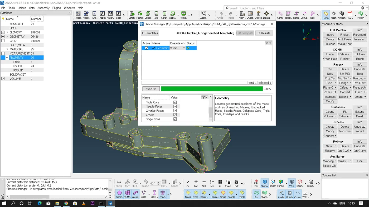
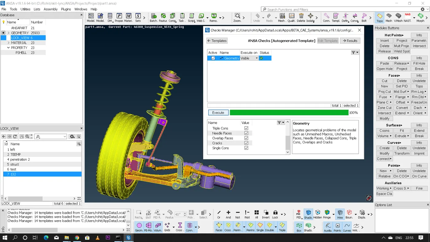
- Geometry check for the complete assembly:
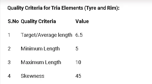
- Now After completion of the geometry clean up we need to perform meshing but before that we need to keyin the quality parameters given.
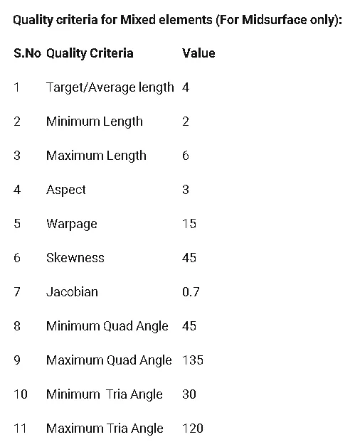
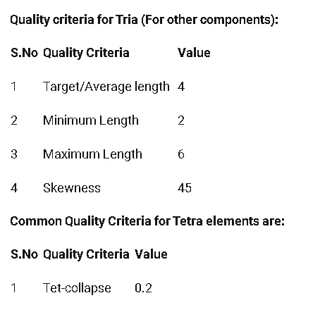
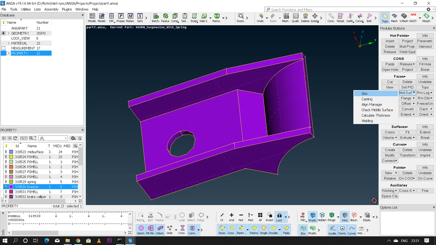
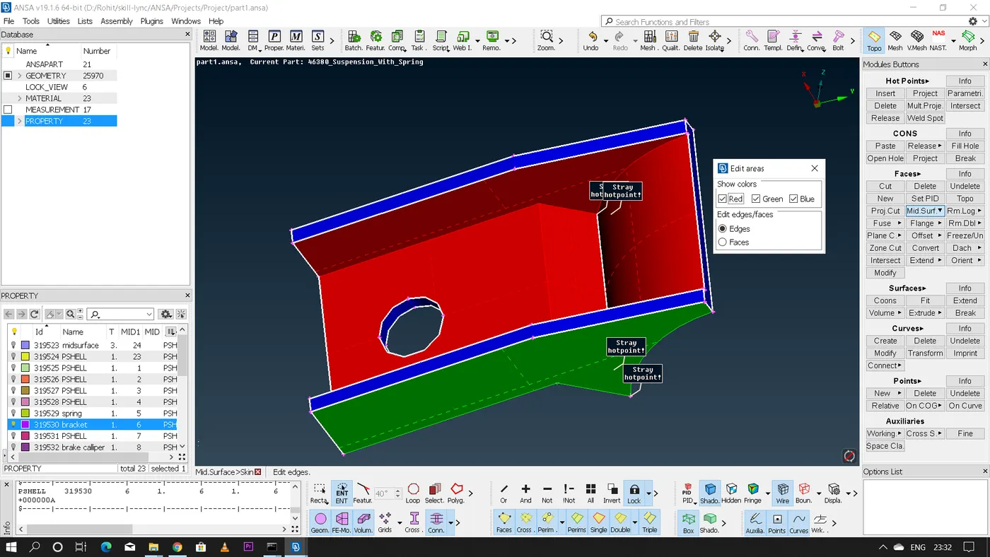
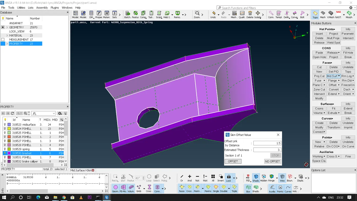
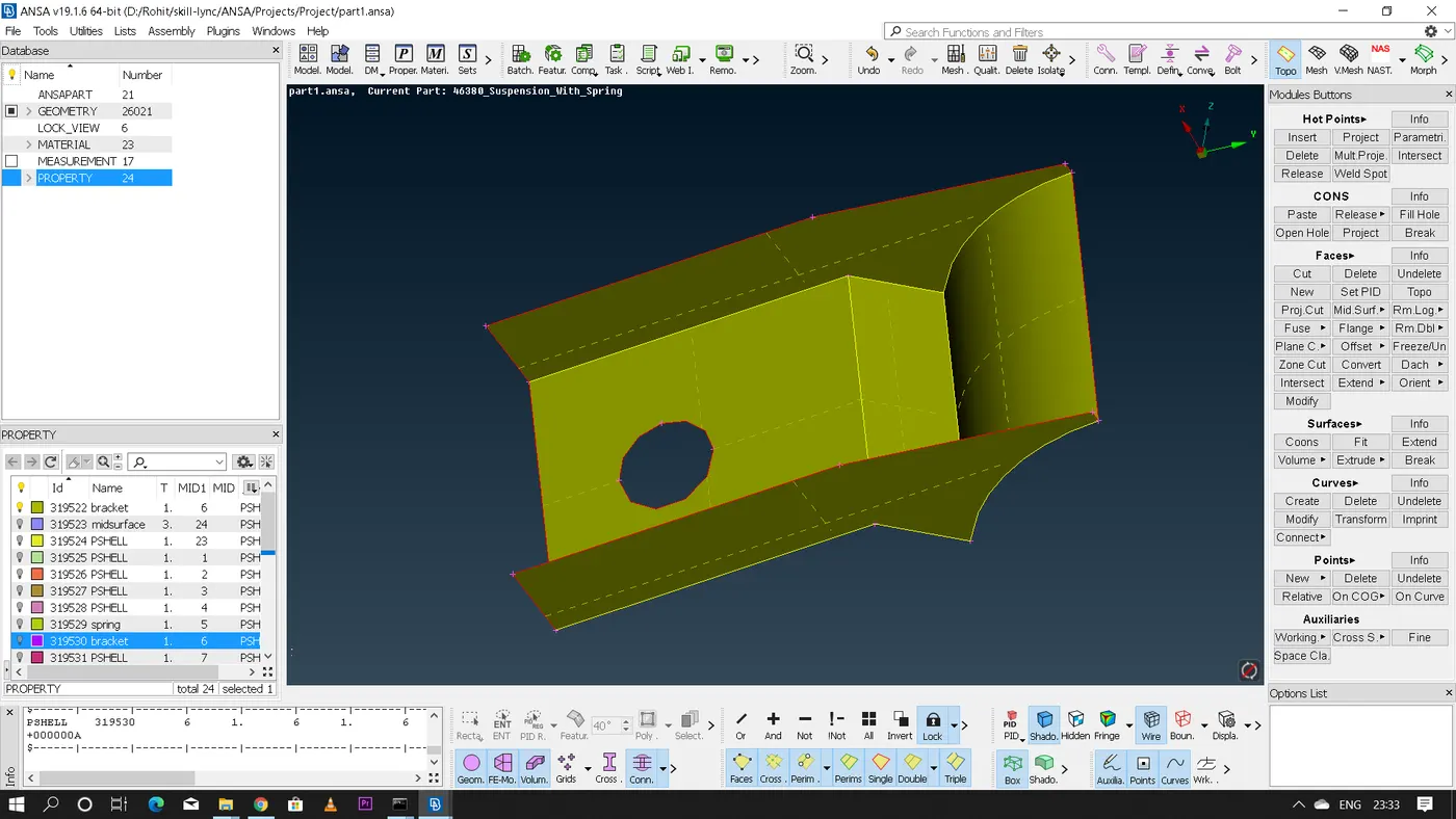
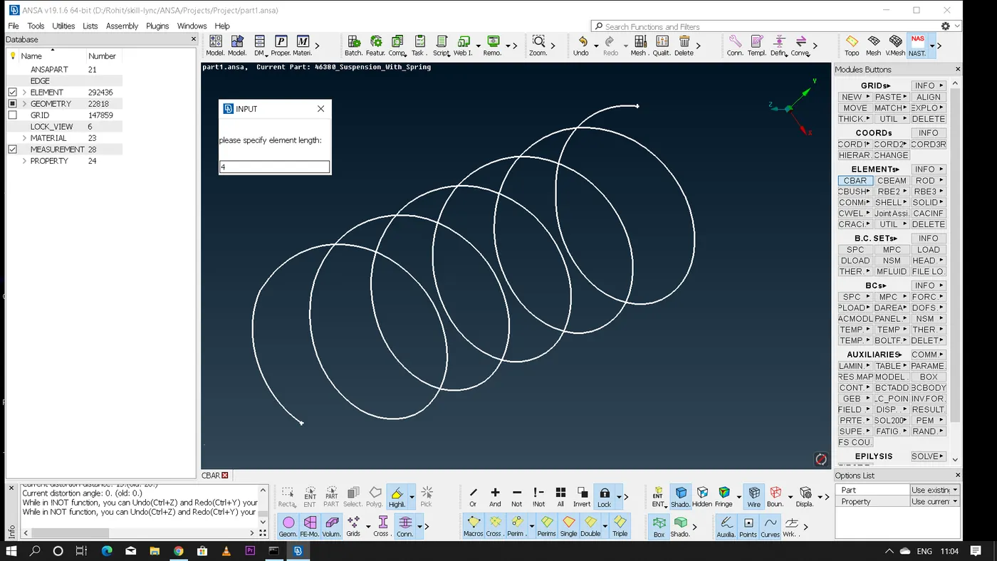
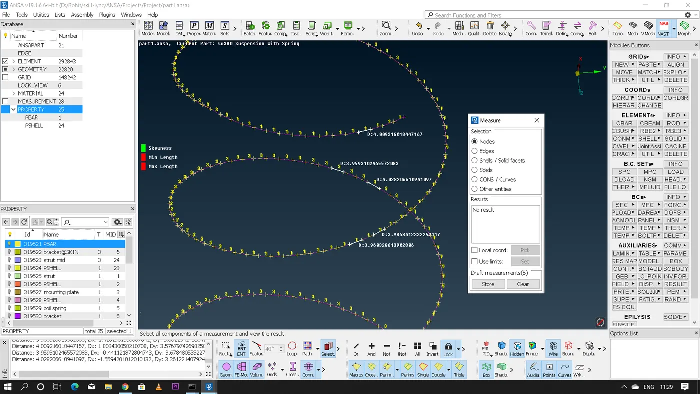
- For meshing here tetra meshing is done for those surfaces whose thickness is above 5mm and 2D-meshing is used i.e, extracting midsurface and creating a mesh for the midsurface using 'Quads' and 'Tria' elements (Mixed element type) for the features whose thickness is uniform and less than 5mm. For the coil spring I went for 1d-element modelling method since it is a much simpler method, whereas by using tetra meshing the surface generated will not be accurate since it is a very complex feature.
- 2D Meshing or Midsurface meshing for components with uniform thickness and a thickness value of less than 5mm.
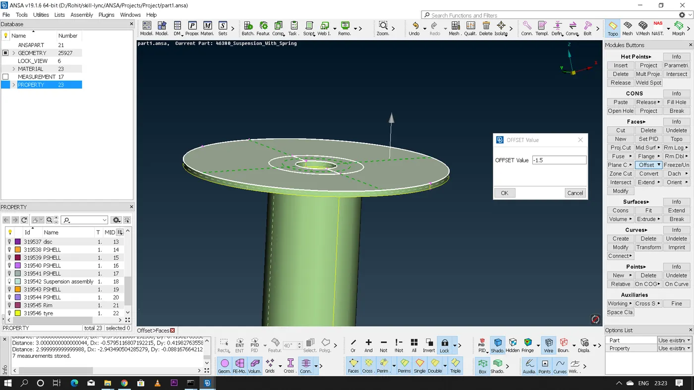
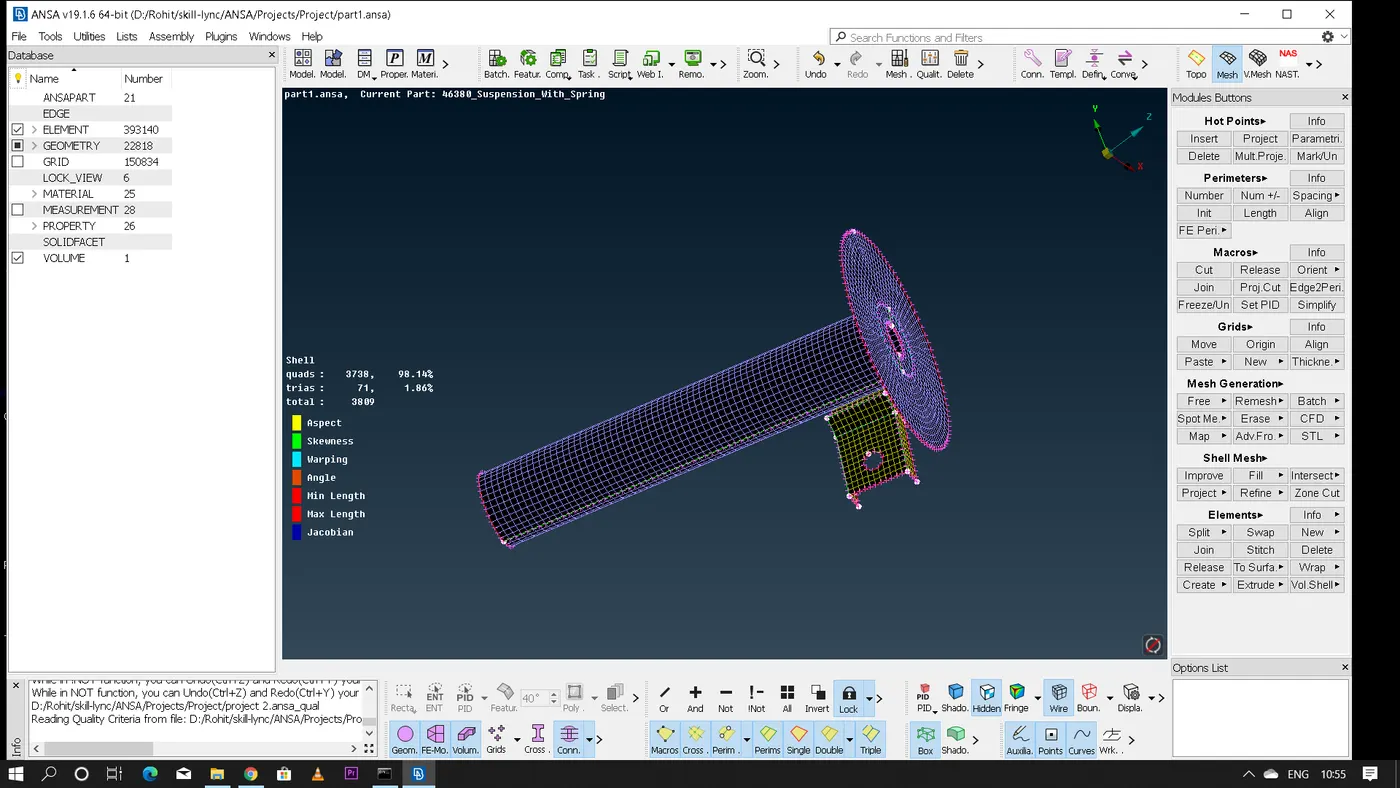
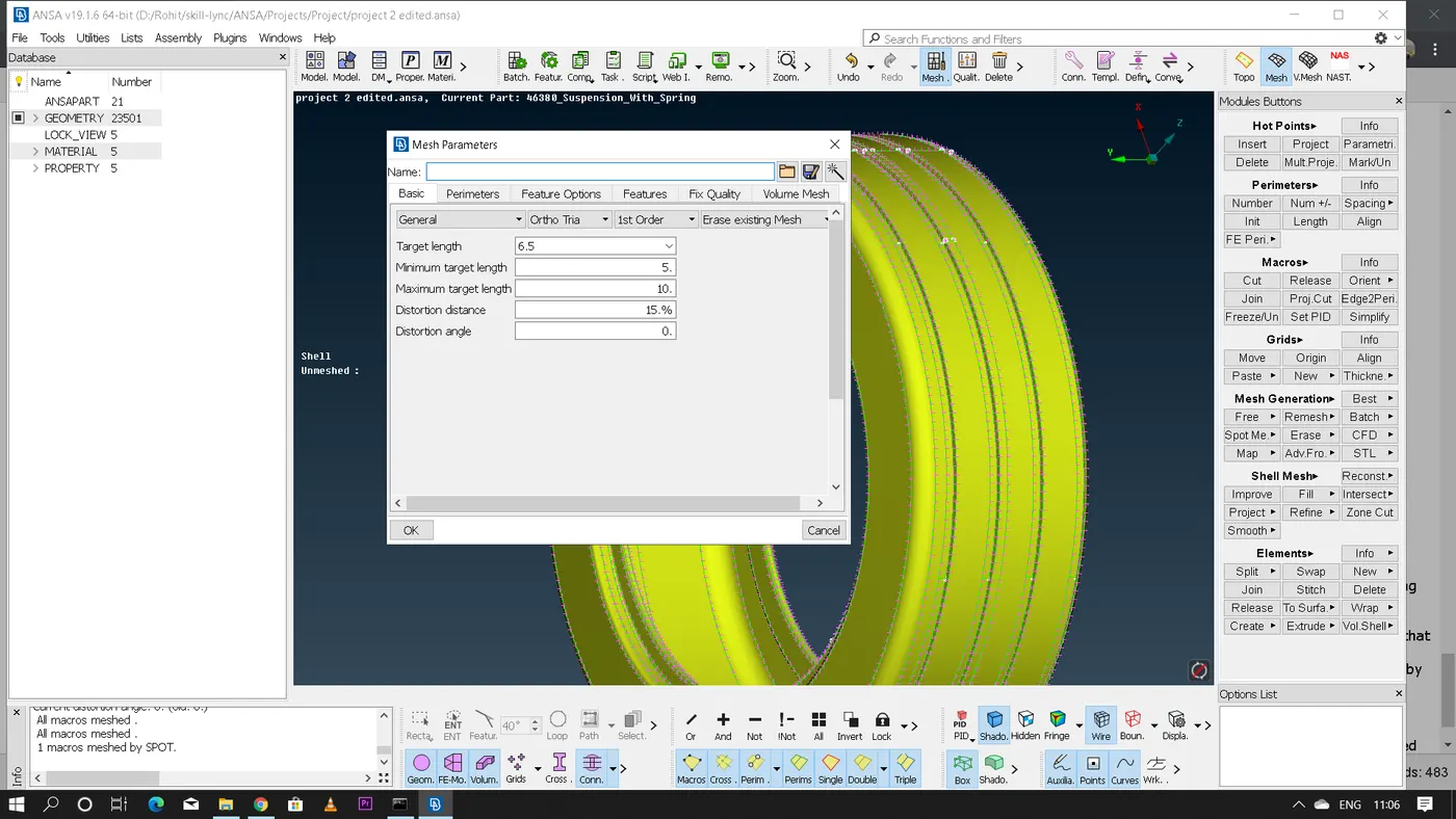
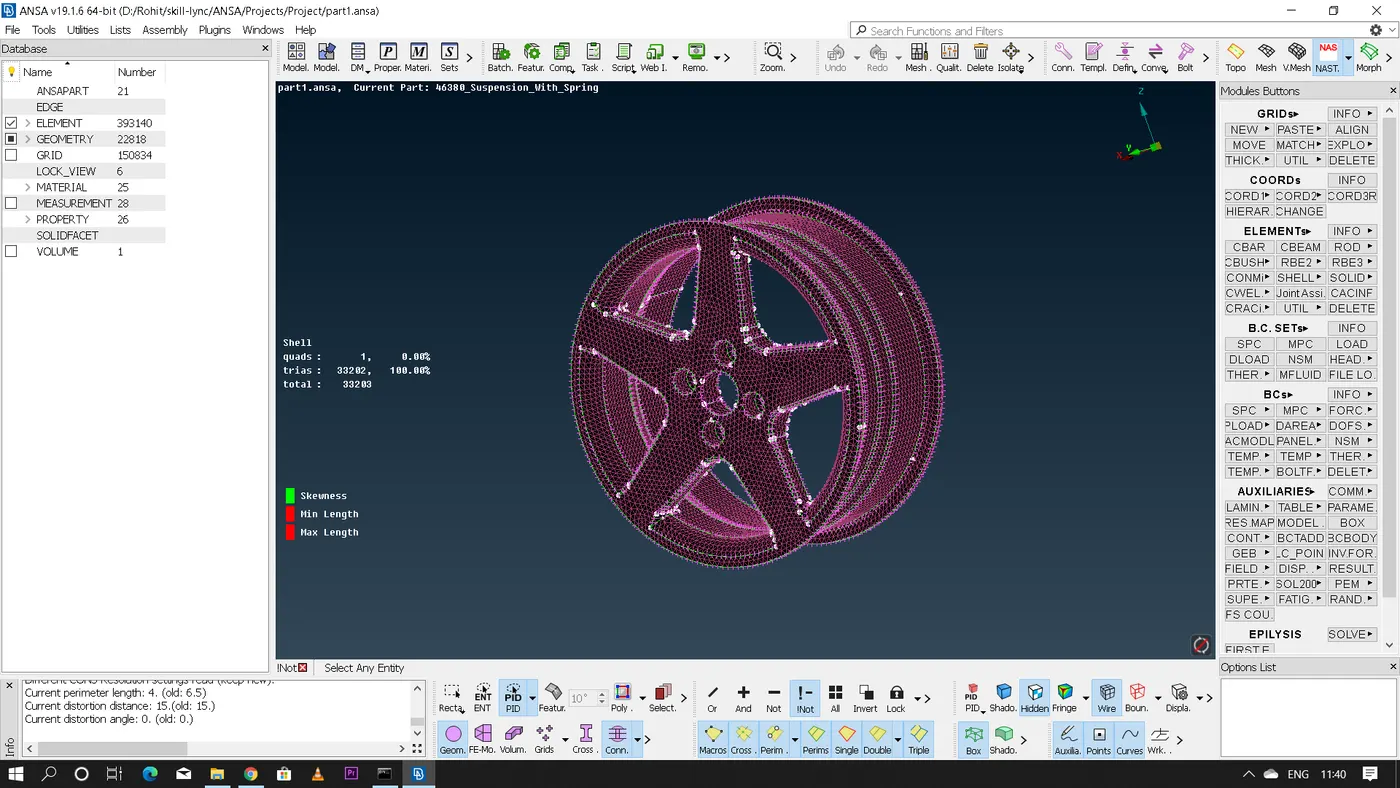
- Ortho-tria meshing or surface meshing for tyre and rim.
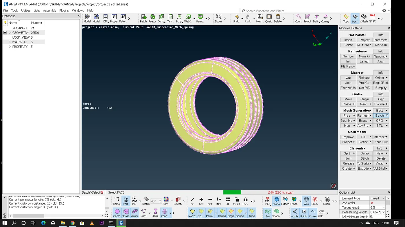
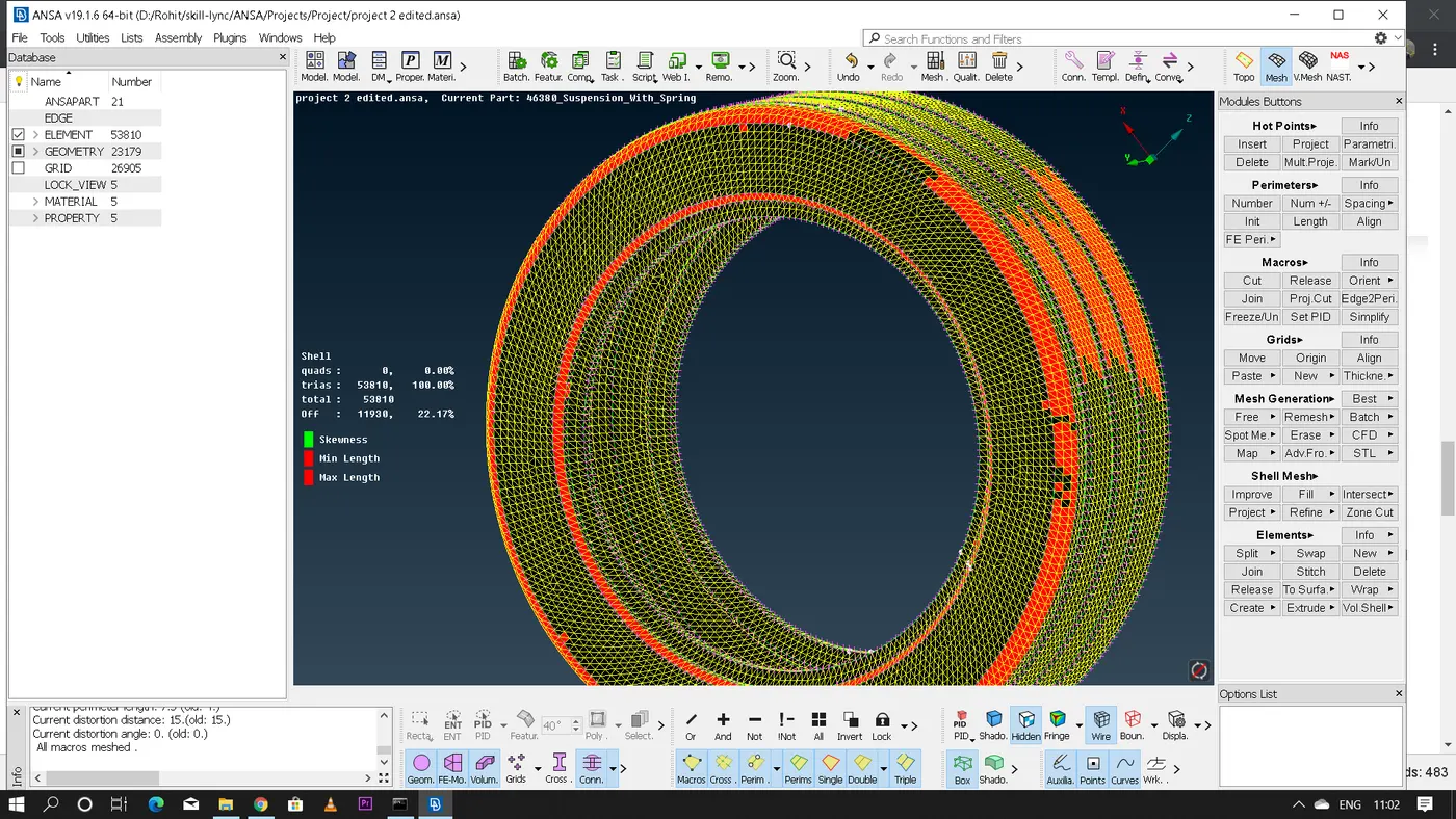
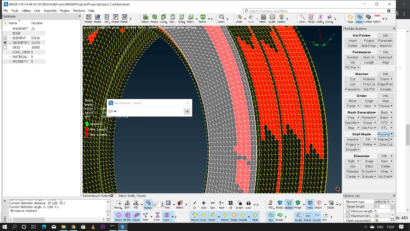
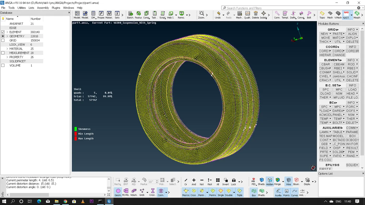
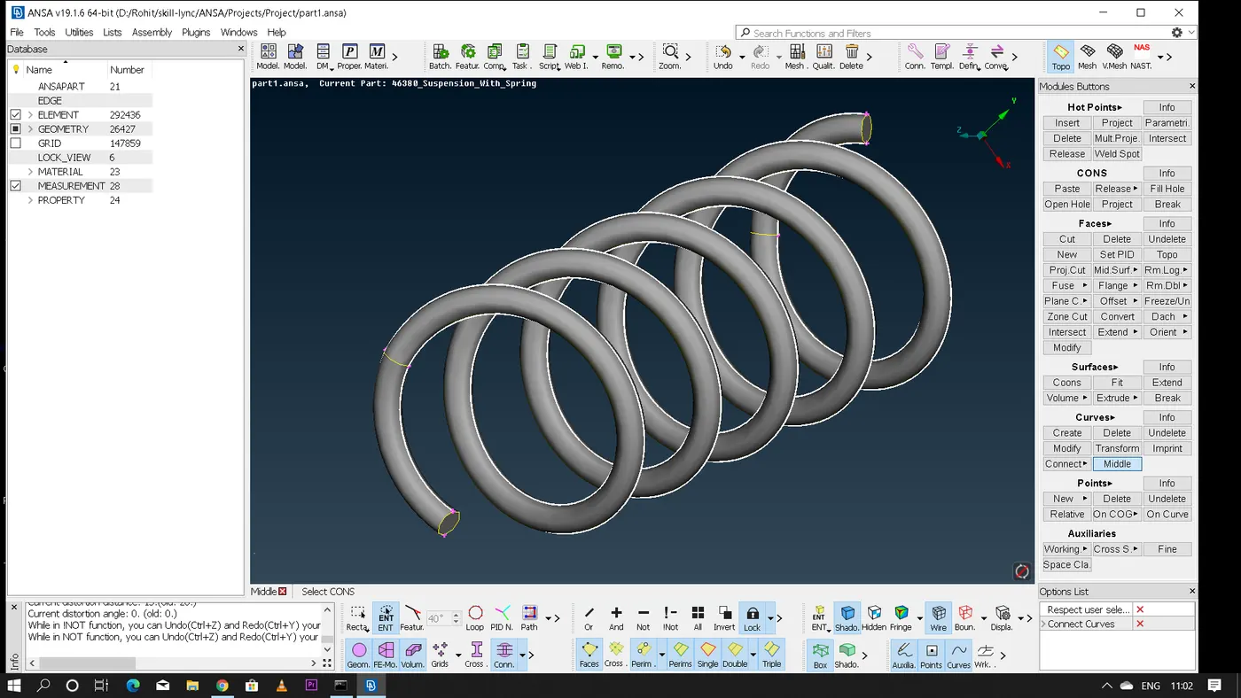
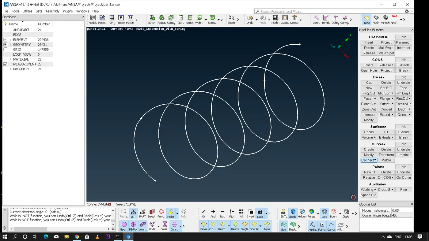
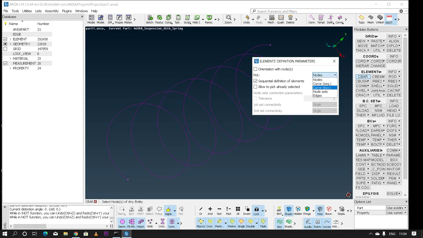
- 1D modelling for coil spring component.
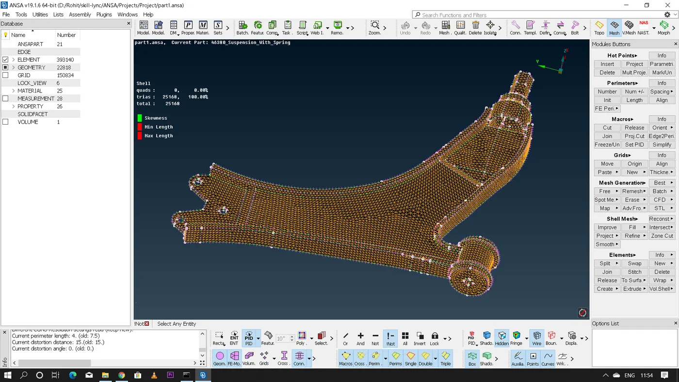
- For the remaining parts ortho tria meshing is done similar to which we did for the tyre and rim surfaces but with the change in quality parameters.
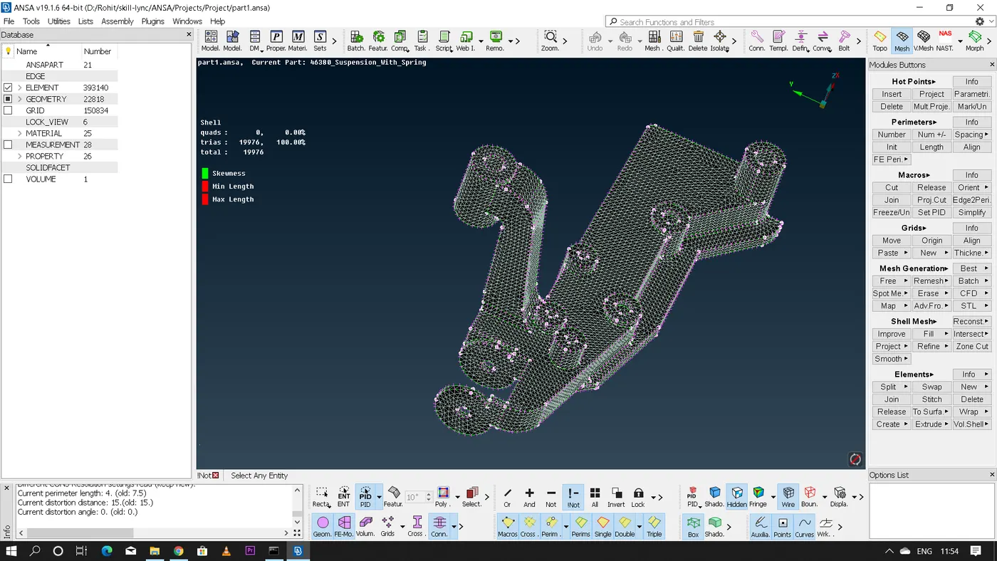

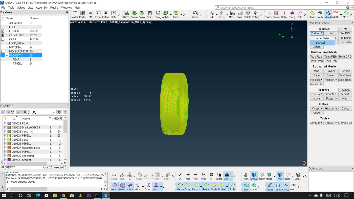
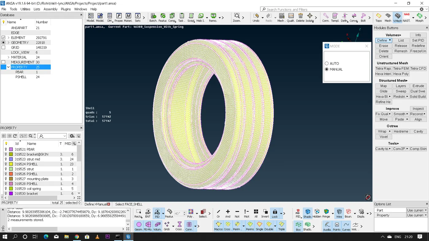
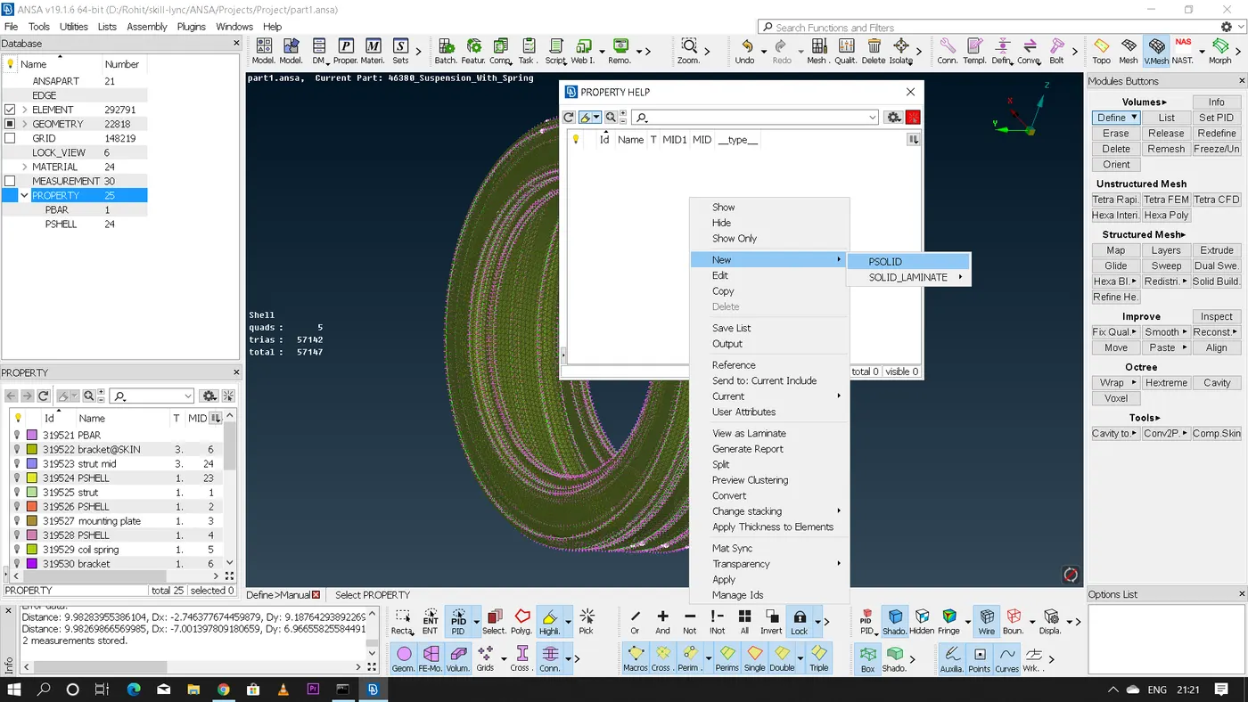
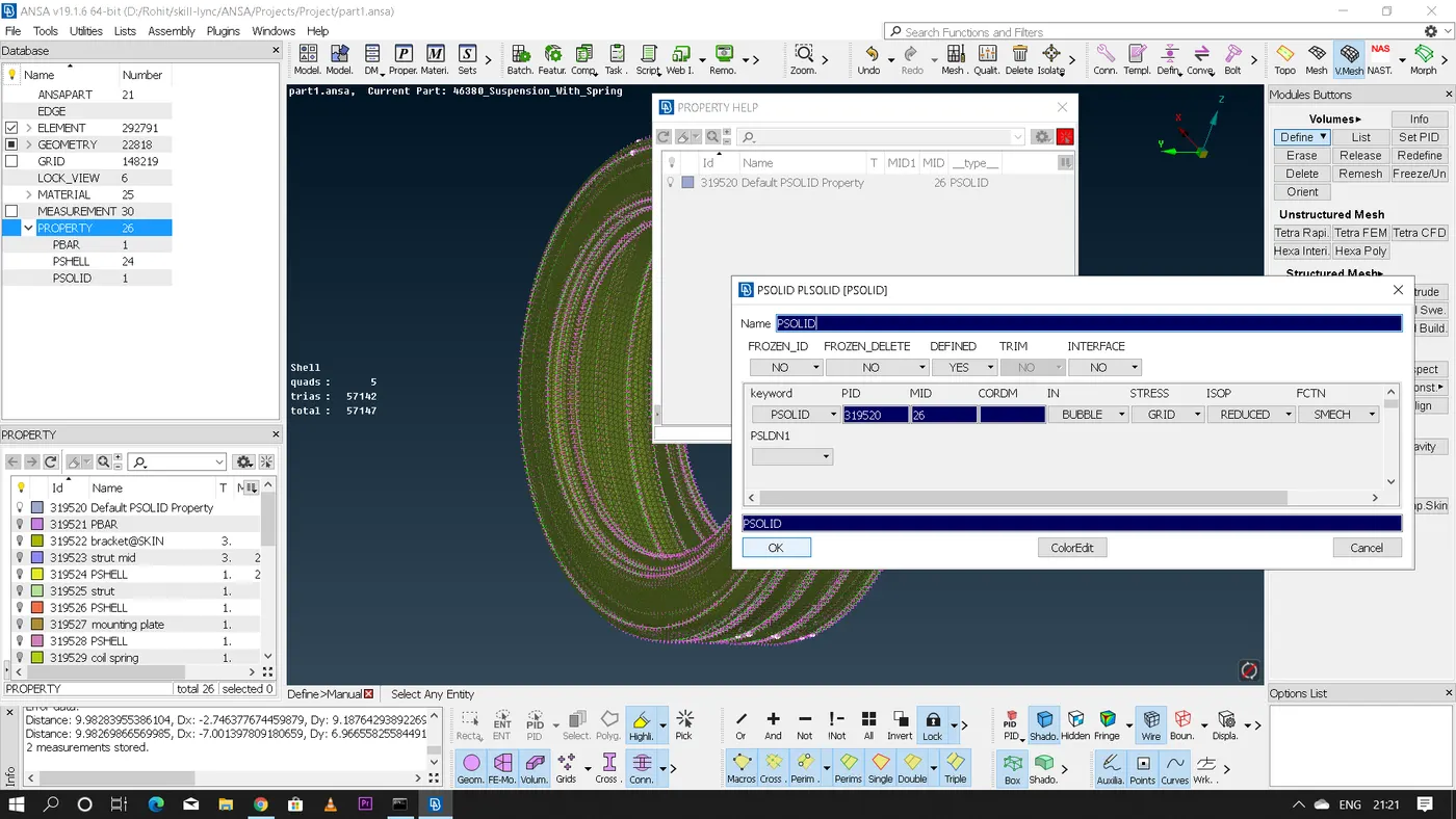
- After completion of meshing all the parts and achieving the required quality criteria now we need to perform volume meshing but for that first we need to define each and every part before performing the volume mesh. Volume mesh can be generated by using either 'Tetra Rapid' or 'Tetra FEM' both the methods will give a similar outcome. In volume meshing we check only for 'Tetra Collapse' in quality criteria. For volume meshing we majorly use 'Ortho tria' and 'Tria' elements for meshing.
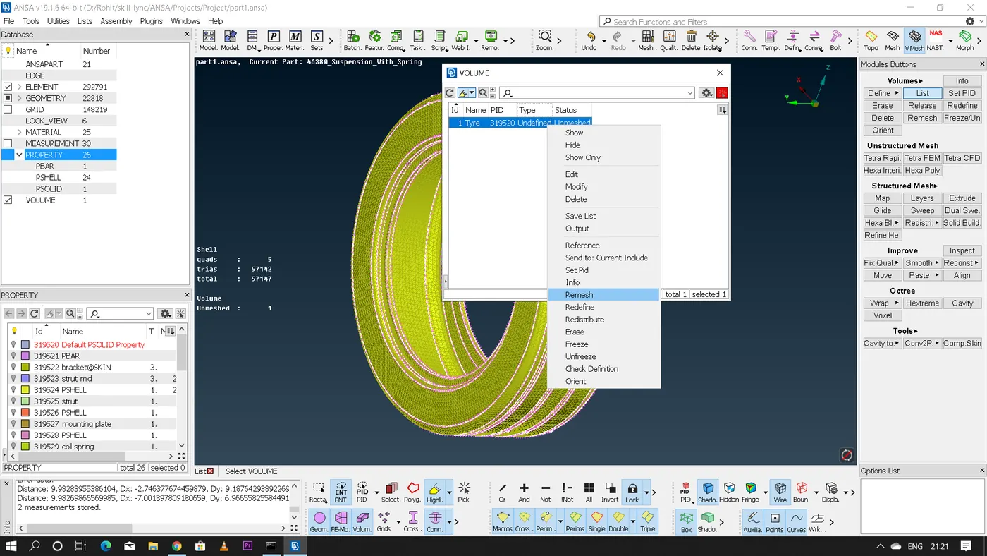
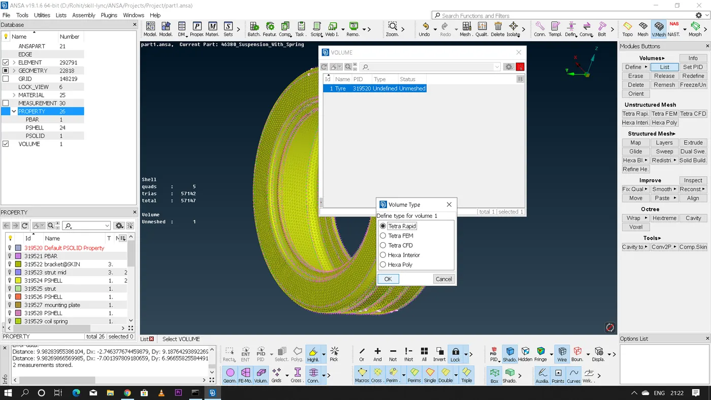
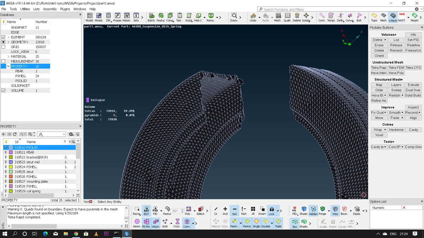
- While performing the Volume meshing there might be some features where we might face some 'penetration error' issues which is due to the improper CAD geometry which can be fixed by deleting that particular surface and creating a new surface over there.
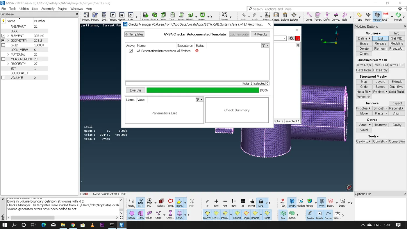
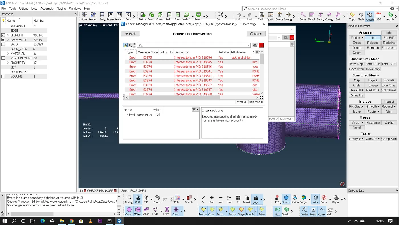
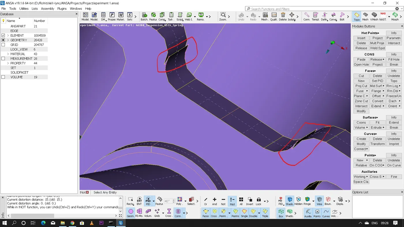
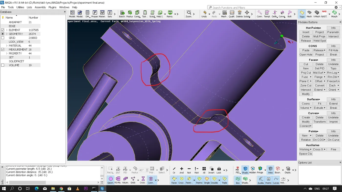
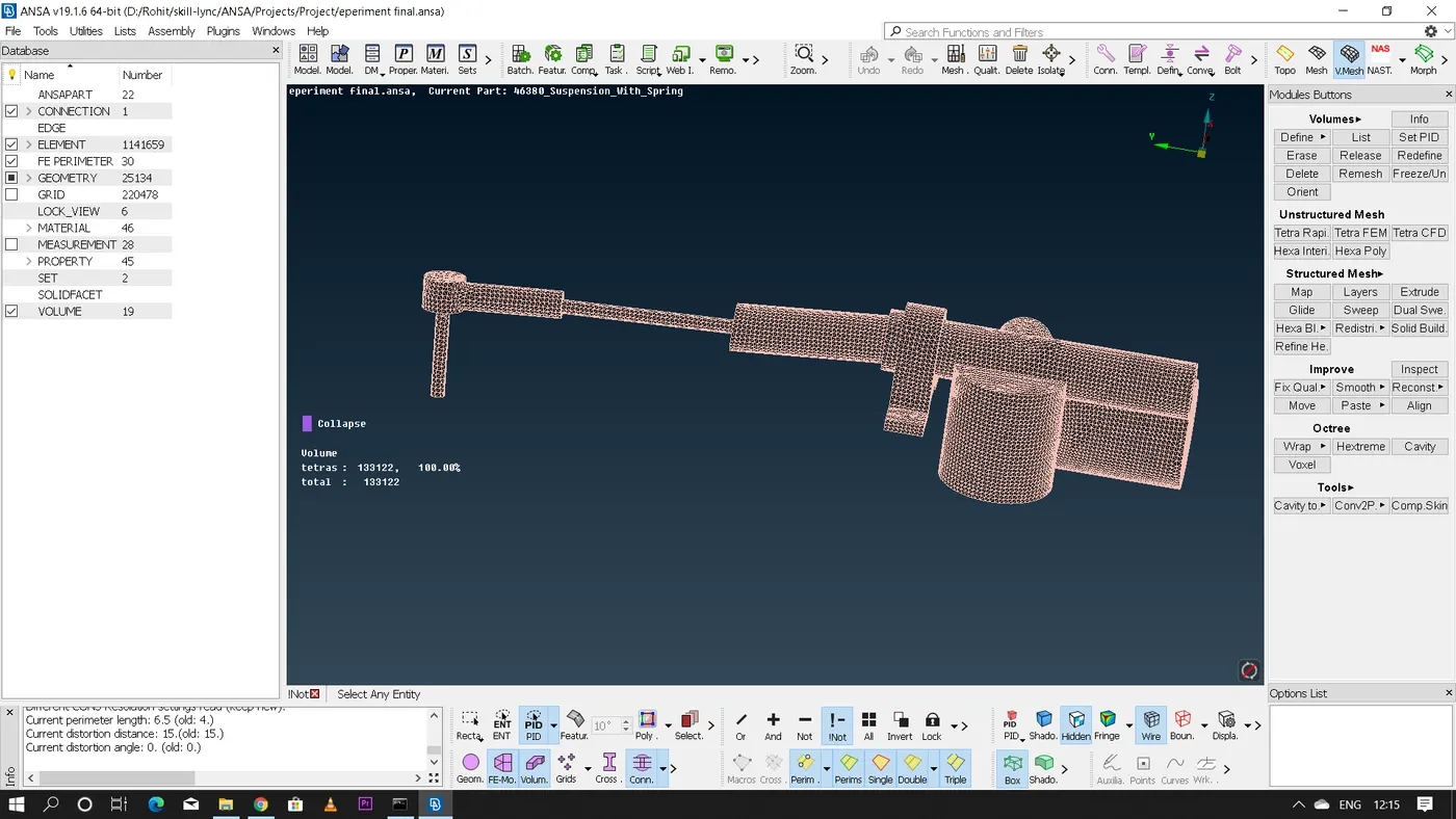
- Similarly we need to perform volume meshing for all the remaining parts.
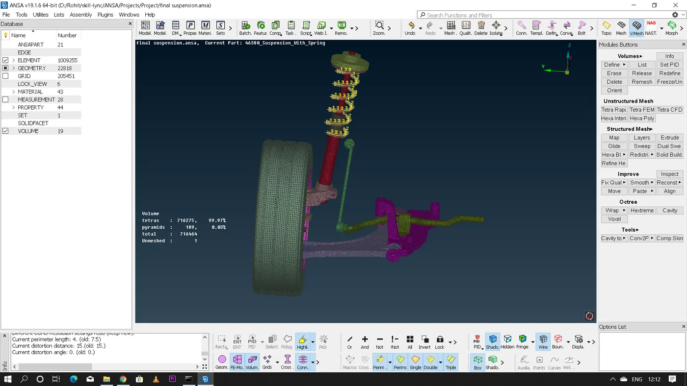
- And finally after completion of volume meshing now we need to give some connections where ever required to rigidise the complete assembly. In most of the places we need to give bolt connections by using RBE2 elements to rigidise the component.
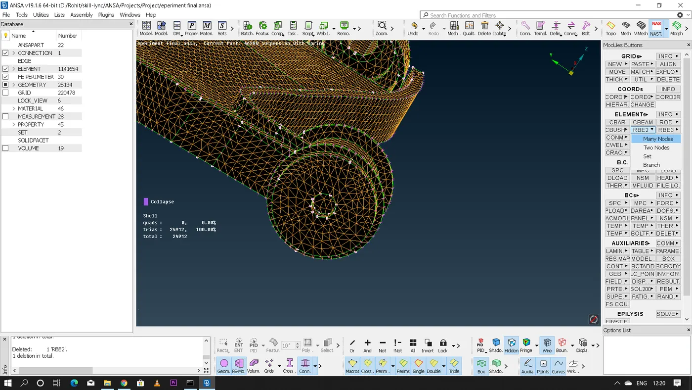
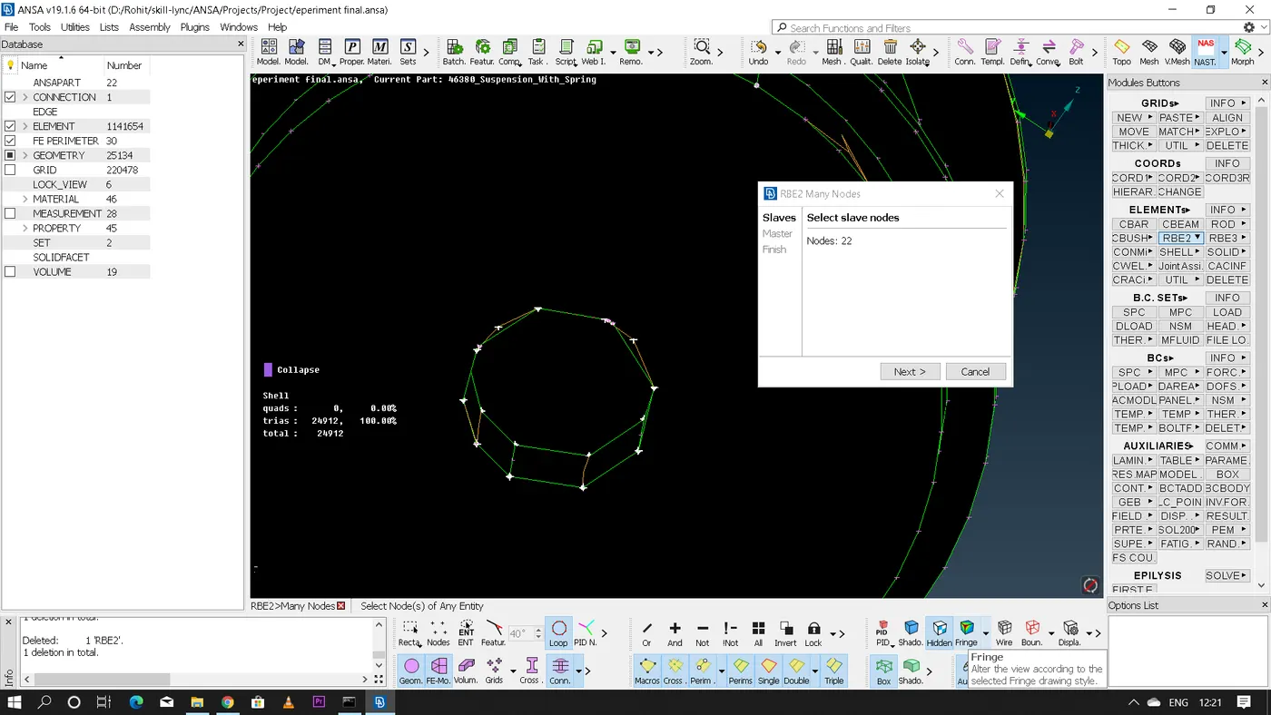

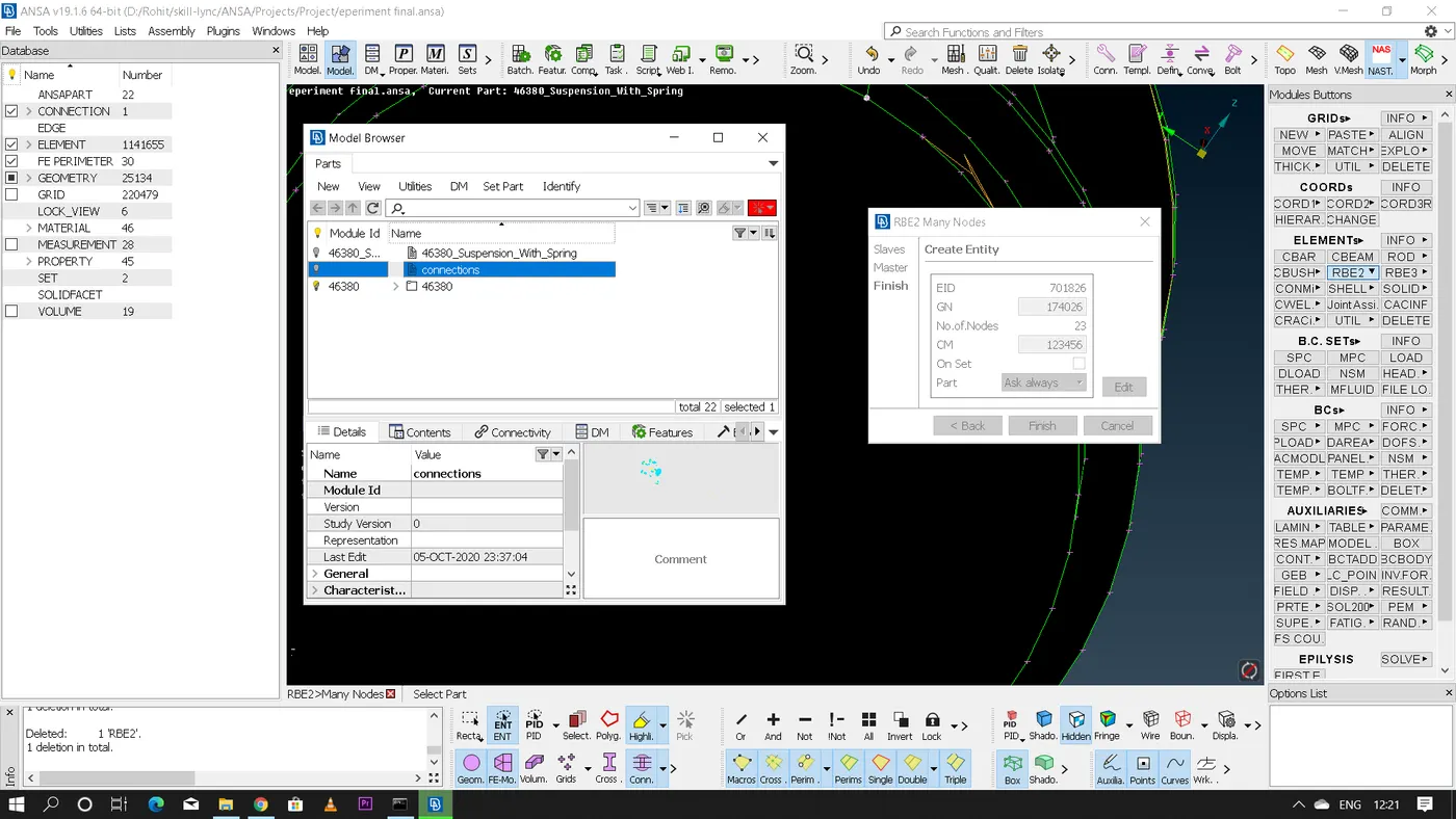
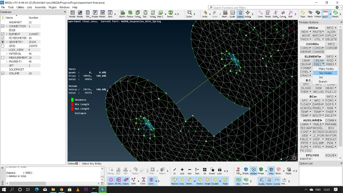
- Rigidising the bracket by deploying a spot weld.
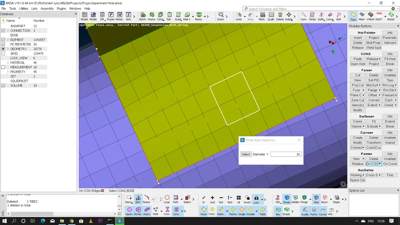
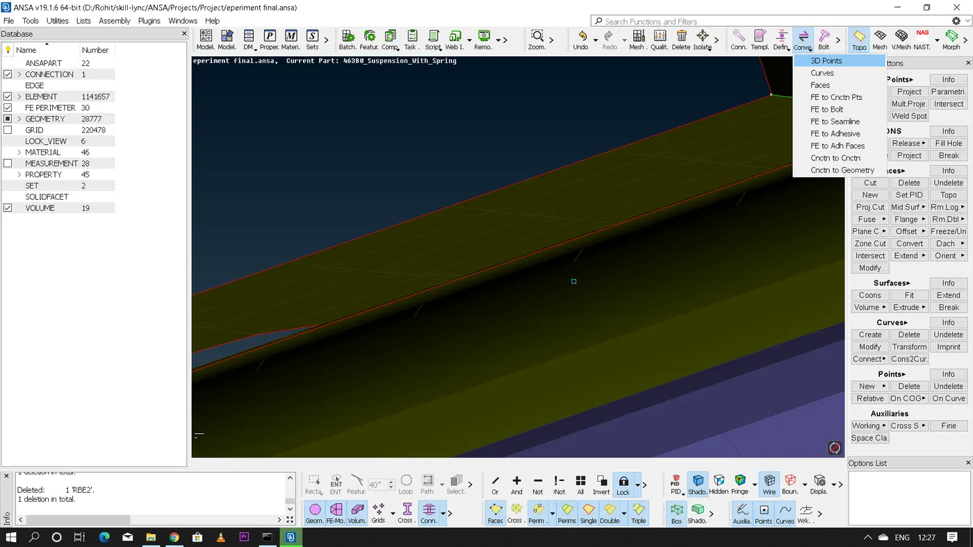
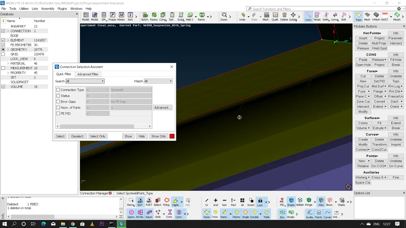
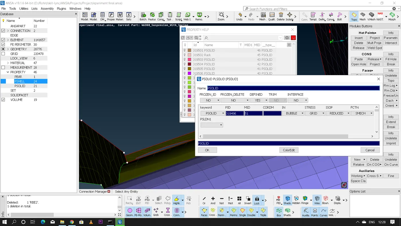
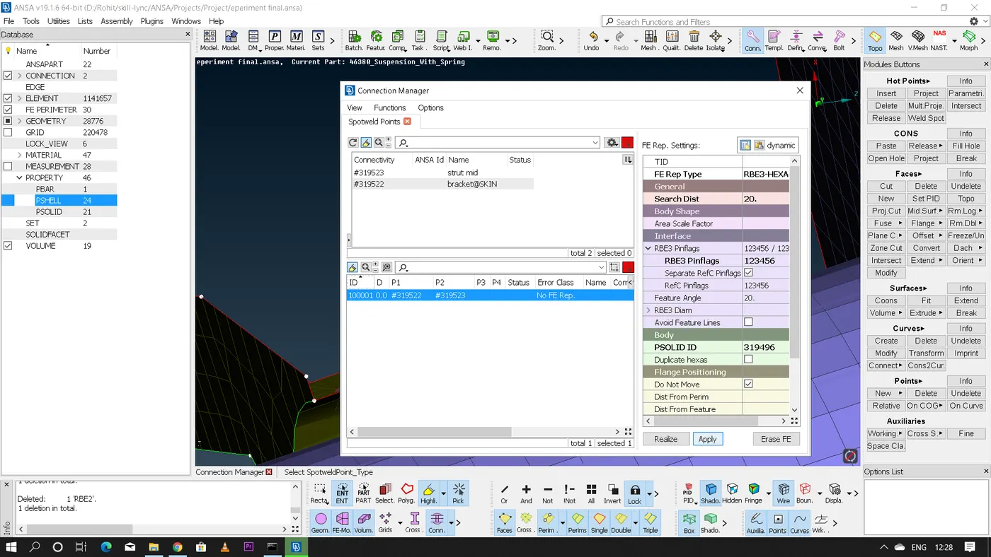
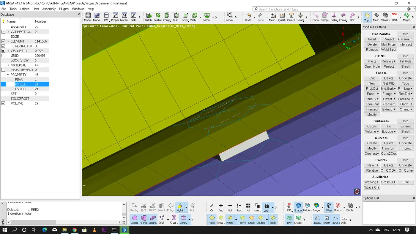
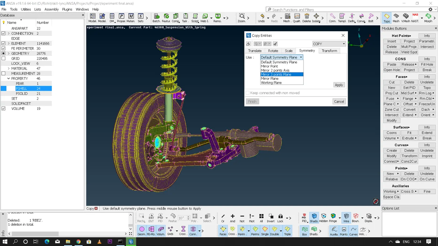
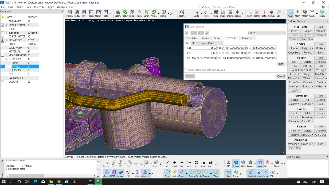
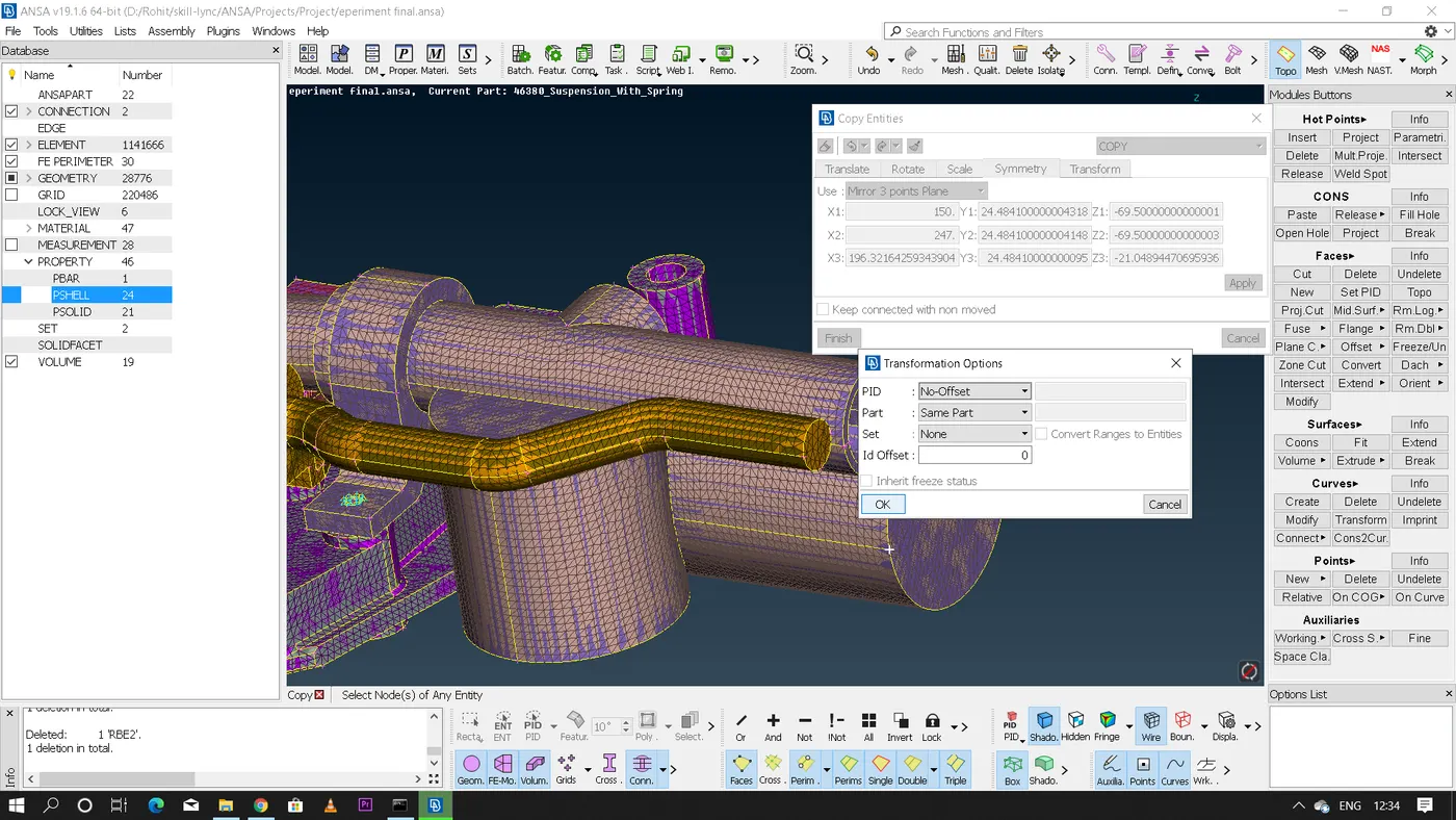
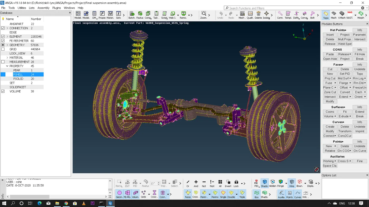
- Final Component with all the required connections deployed and mirroring with the help of "Transform >> Symmetry >> Mirror 3 point plane".
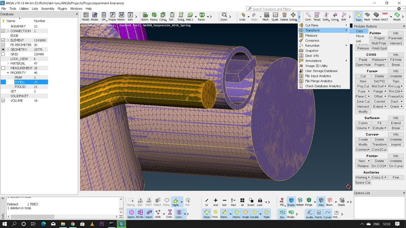
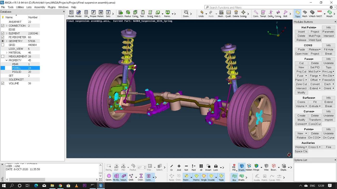
- Link for the Suspension spring assembly:
https://drive.google.com/file/d/1LMt7qLvSOCY9KWeKpYBzAdTuH_ObZZBr/view?usp=sharing
* Learning Outcomes:
This model really helped me a lot to revise all the previously learnt concepts once and here i also learnt a new concept of fixing penetration errors which i did not overcome in any of the previously practised models.
* Conclusion:
Hence the given 'Suspension Assembly' is successfully volume meshed using the tetra elements as per the quality criteria with zero off elements and rigidised the component by deploying an appropriate connections wherever required.