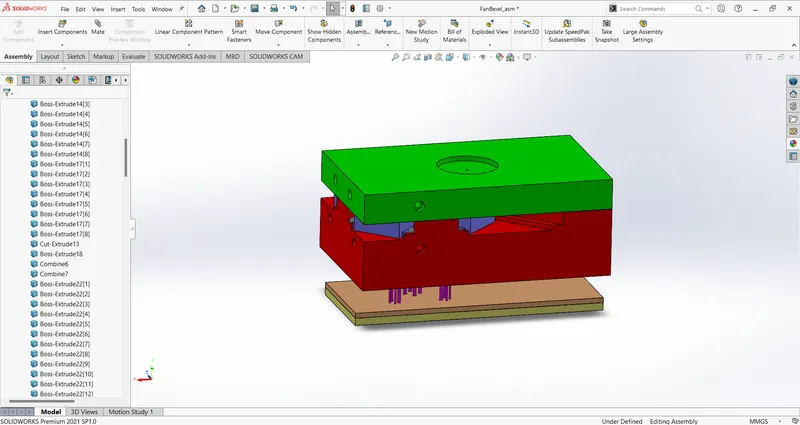
Project 2
Project - 2
Mold Design for CPU Fan Bezel
1. Creation of Tooling Direction and do Draft Analysis on the part.
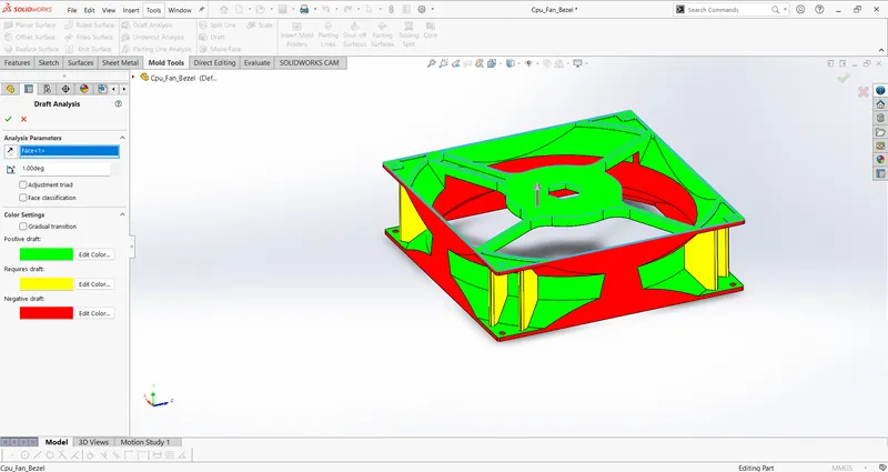
The tooling axis for this part is taken normally to the top face. Then, draft analysis is done along the tooling axis.
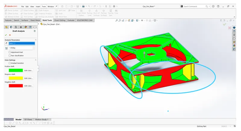
The above-marked regions on the 4 sides of the fan bezel can only be cleared with a slider. And shut-off surfaces are created for the area that is common to both core and cavity.
2. Check for any problem with the part to can be a thread for creating mold.
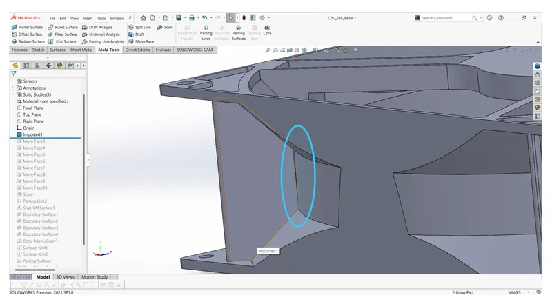
There is a small gap between the above walls. This could be a serious problem in creating the core and cavity surfaces.
This gap is removed by using the move face command.
3. Apply for shrinkage allowance by scaling the part by 0.6%(Assuming the value of shrinkage in ABS material is 0.6% ).
4. Creating a parting line by considering draft analysis and choosing a perfect location for the splitting of the mold.
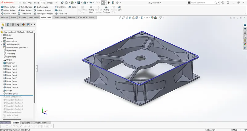
5. Creation of shut off surfaces
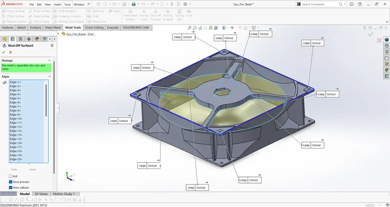
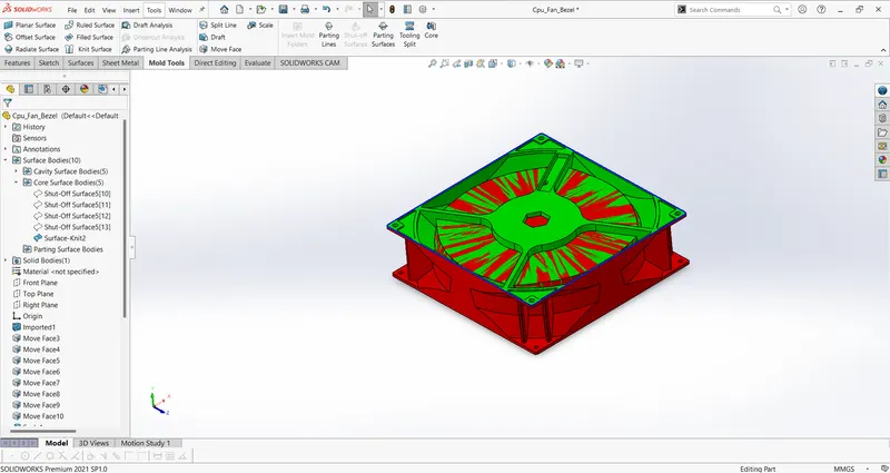
6. Core and Cavity side surfaces:
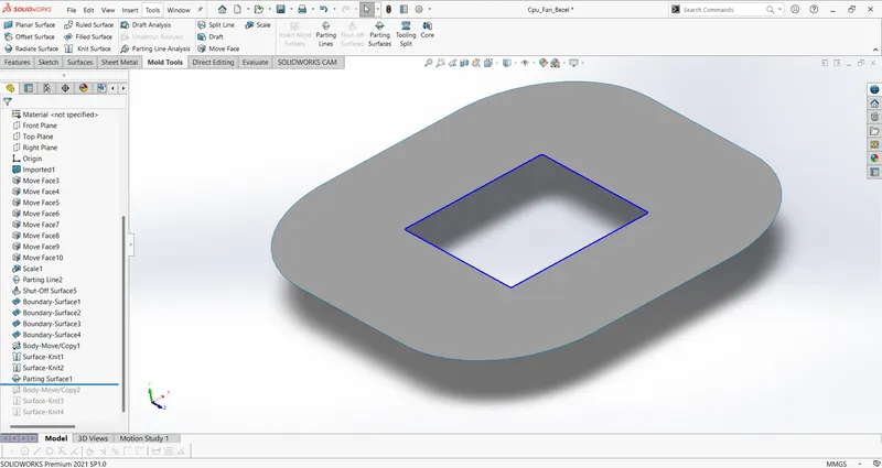
7. Parting Surface:
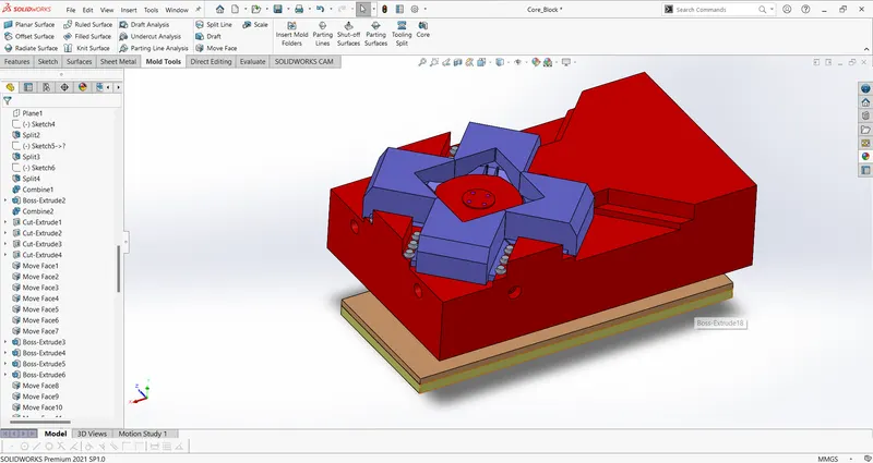
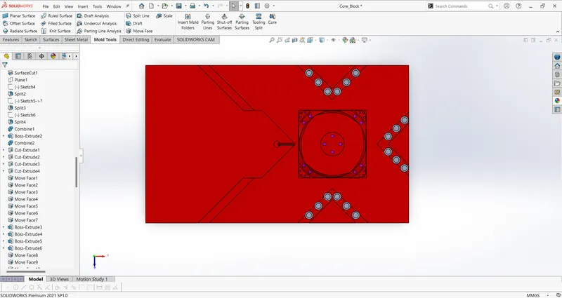
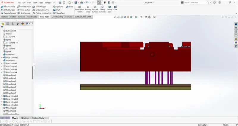
8. Core Block with sliders, Ejection system, Runner & Gate, and Cooling channels:
9. Cavity Block:
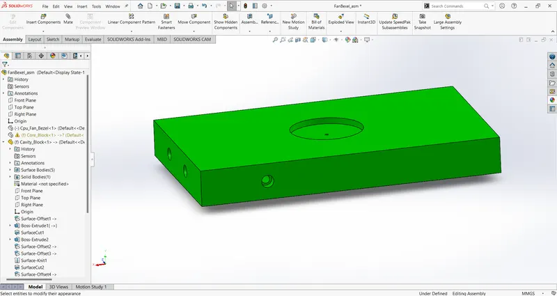
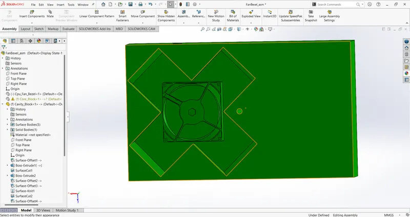
Complete Assembly: