Project 2
Aim: To design and document the wiring harness layout for a specified car body in CATIA V5, ensuring adherence to all packaging rules and industry best practices. This includes routing the wiring harness, applying protection coverings where necessary, and preparing a detailed flattened view drawing that demonstrates proper design and organization of the wiring system.
INTRODUCTION
A wire harness, or wiring harness, is a protective sheath made from thermoplastic or thermoset materials designed to cover and safeguard electronic wires from environmental damage. In modern automobiles, wiring harnesses are crucial assemblies that include wires, connectors, and other electrical components, facilitating the transmission of signals throughout the vehicle. Their design is essential for managing the complex electrical systems found in today's vehicles.
DESIGN METHODOLOGY
Here are the key rules for wiring harness design:
1 Maximum Distance Between Clamps: 200mm.
2 Minimum Branch Length: 50mm.
3 Minimum Distance Between Clip and Nearest Branching Point: 25mm.
4 Minimum Distance Between Two Straight Connection Points: 200mm.
5 Minimum Distance Between Two Breakout Points: 50mm.
5 Branch Limit: No more than 4 branches from a single branch point.
6 Clip and Clamp Placement: Ensure positive clearance and safety; use clips like fir tree clips as part of the wire harness routing.
7 Slack Provision: Provide enough slack to avoid damage during door operations.
8 Ease of Manufacturing and Maintenance: Design for easy installation, removal, and maintenance.
9 Cost Effectiveness: Consider cost efficiency in the bundle package.
10 Avoid Blind Zones: Prevent harness routing and clipping in areas that are difficult for assembly or service.
11 Proper Slack at End Connectors: Ensure no tension on the wire bundle.
12 Protection from Sharp Edges: Avoid sharp edges or provide protective parts to prevent damage.
13 Avoid Routing Through Small Holes: Minimize chaffing and handling during installation.
14 Separate Branch Points for Connectors: Ensure separate branch points to avoid errors.
Step 1: Retrieve the CAD data for the Back Door from the designated source.
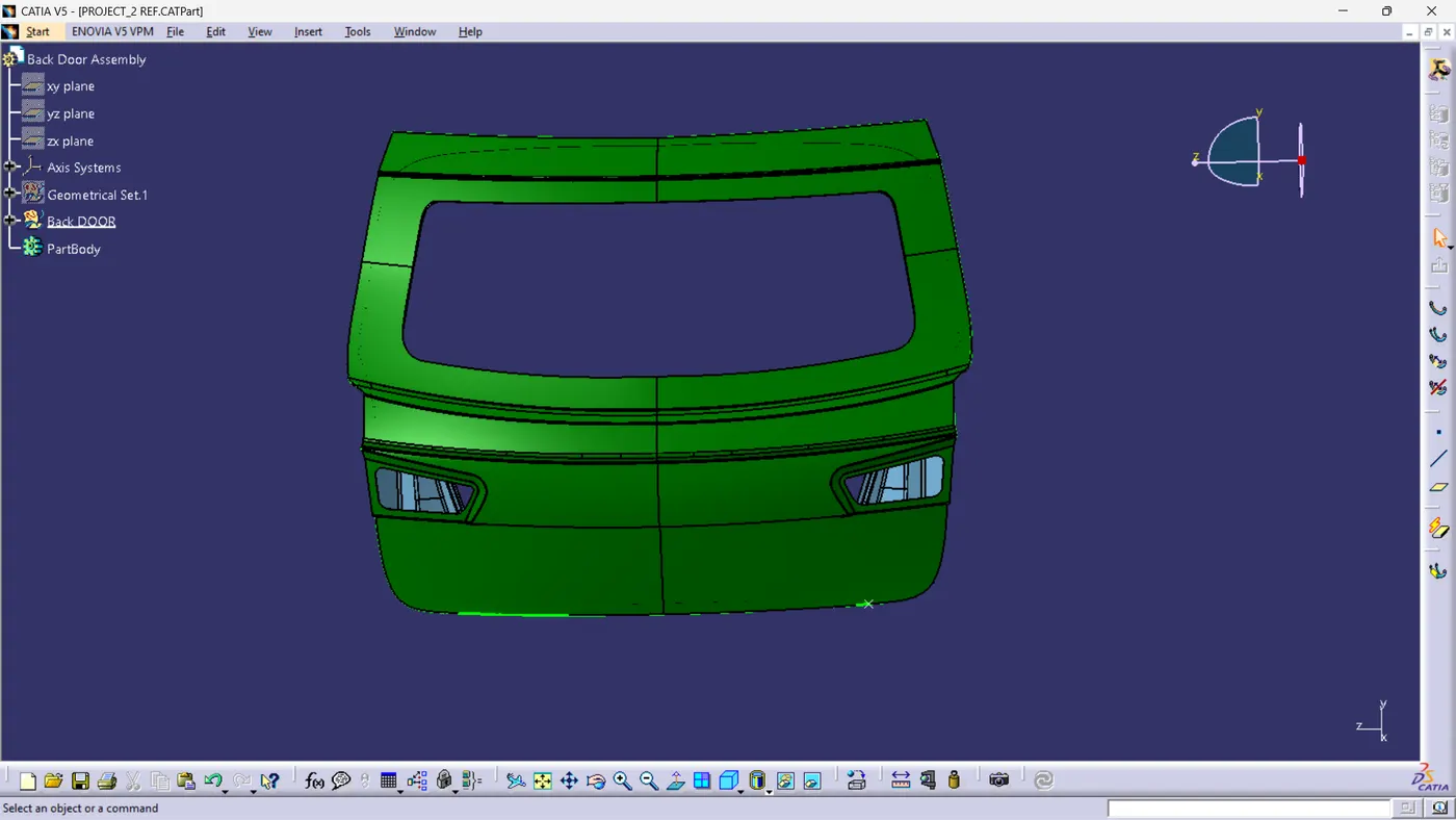
Step 2: Plan the routing path for the wiring harness, specifying the route it will follow through the system.
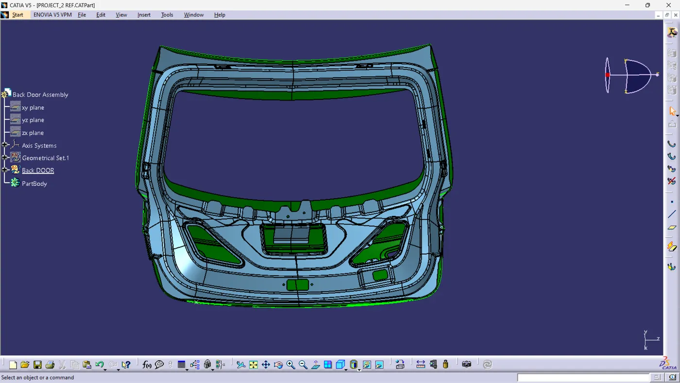
Step 3: Creating the context assembly
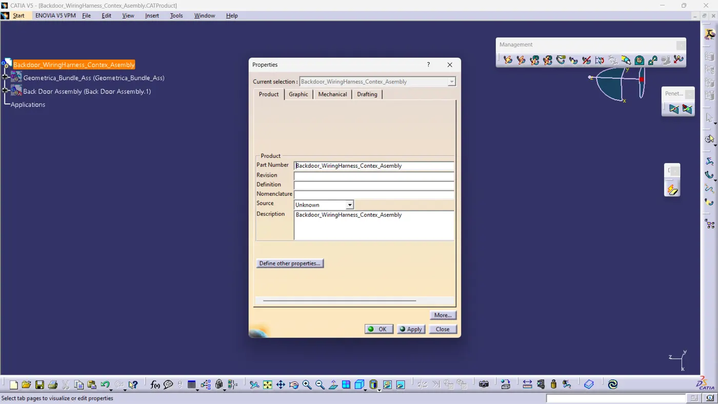
Now add the back door CAD data into the context assembly and also creating the geometrical bundle product file inside the context assembly.
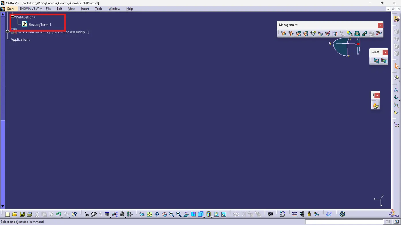
Define the geometrical bundle product file electrically using the geometrical bundle command.
Create a new product file and rename it to "Back Door Harness Assembly Context.
Step 4: Select and add the appropriate connectors from the connectors catalog.
The Back Door Harness Assembly requires the following connectors:
· Interconnection Connector: 1
· Top Mounted Stop Light Connector: 1
· Defogger Connectors: 2
· Brake Light Assembly Connections: 2 (Left Hand and Right Hand)
· Number Plate Light Connections: 2
· Wiper Motor Connection: 1
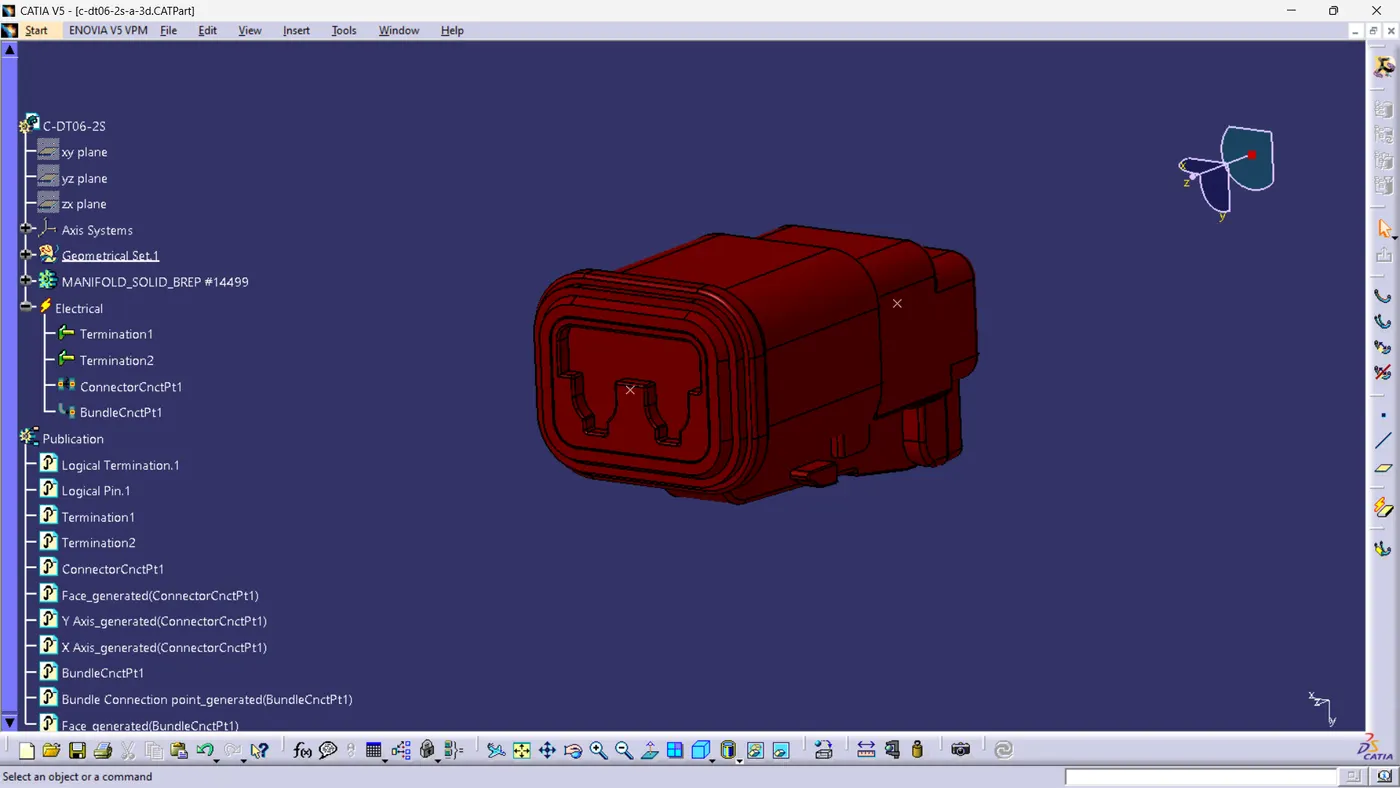
C-DT06-2D
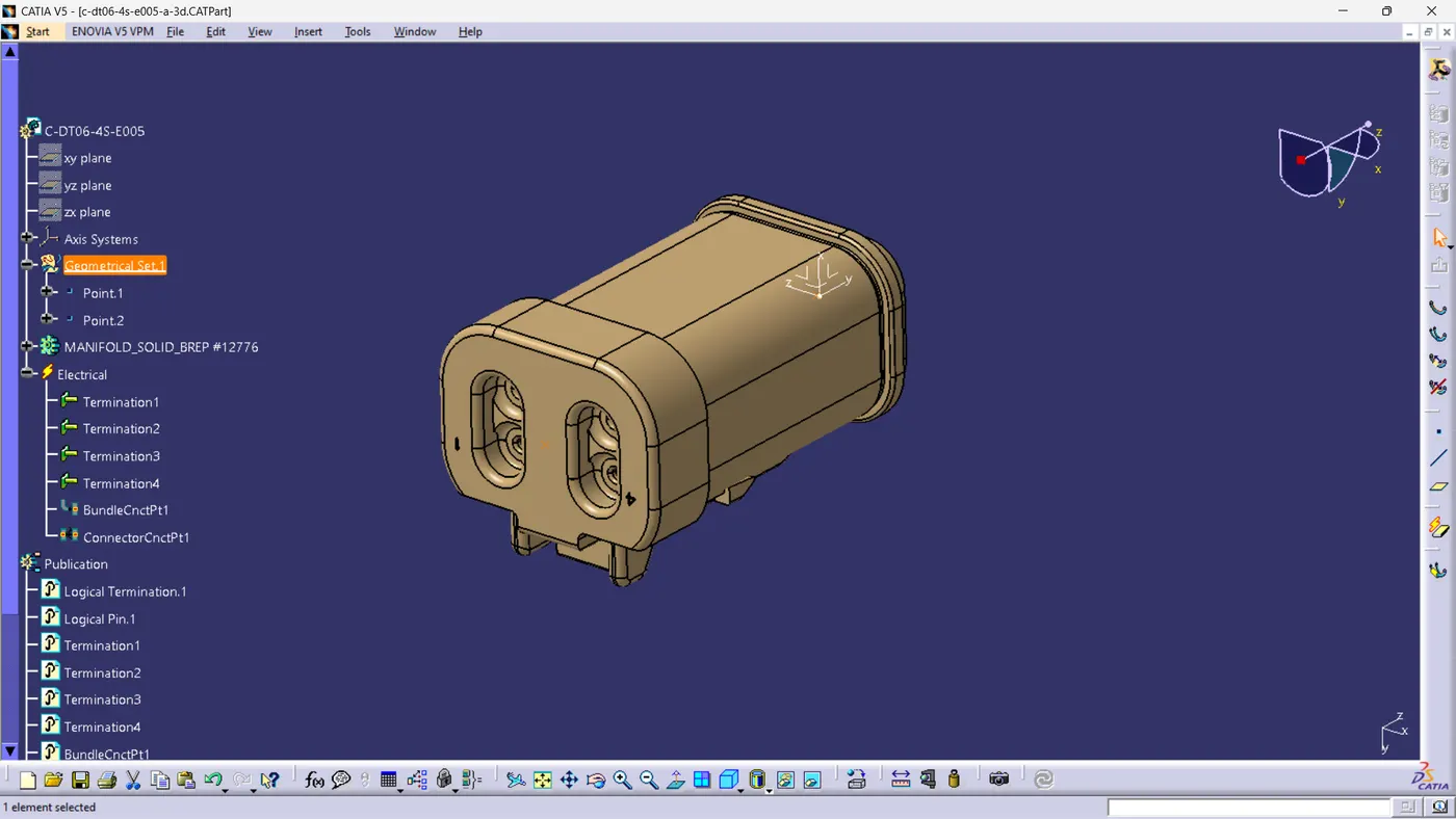
C-DT06-4S-E005
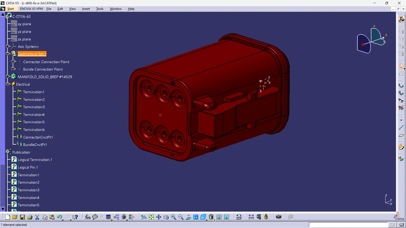
C-DT06-65
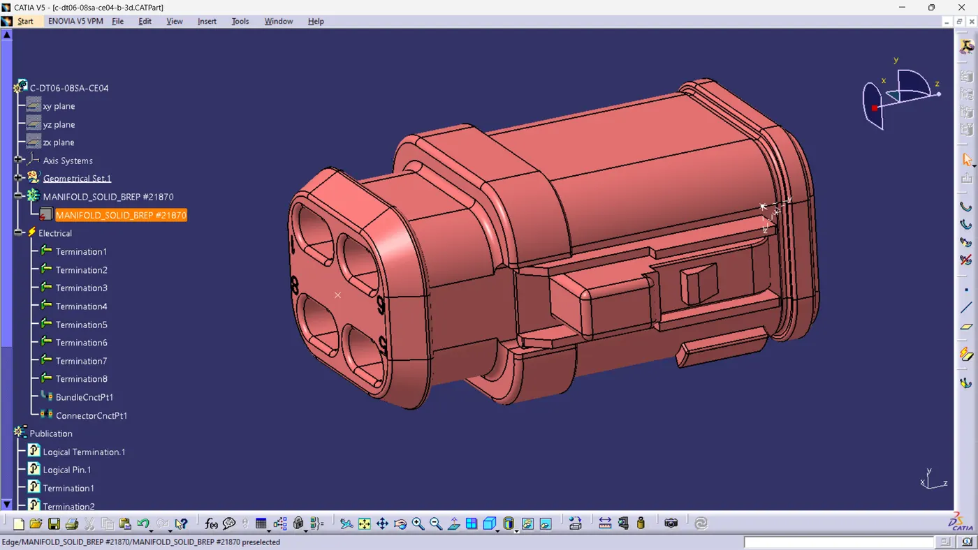
C-DT06-08SA-CE04
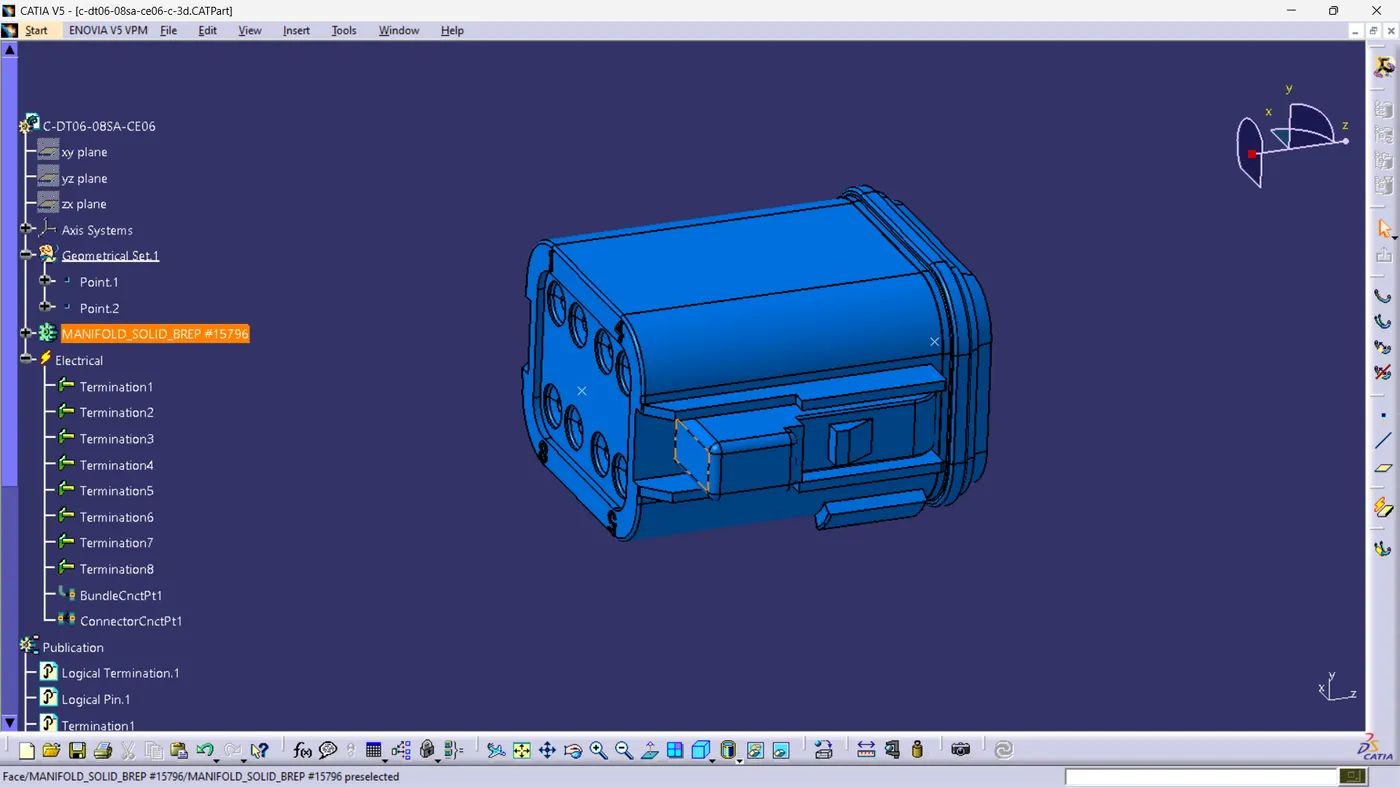
C-DT06-O8SA-CE06
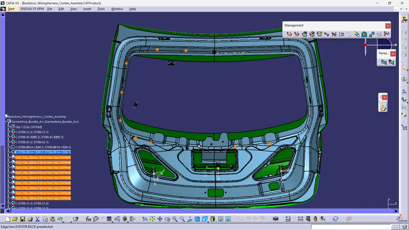
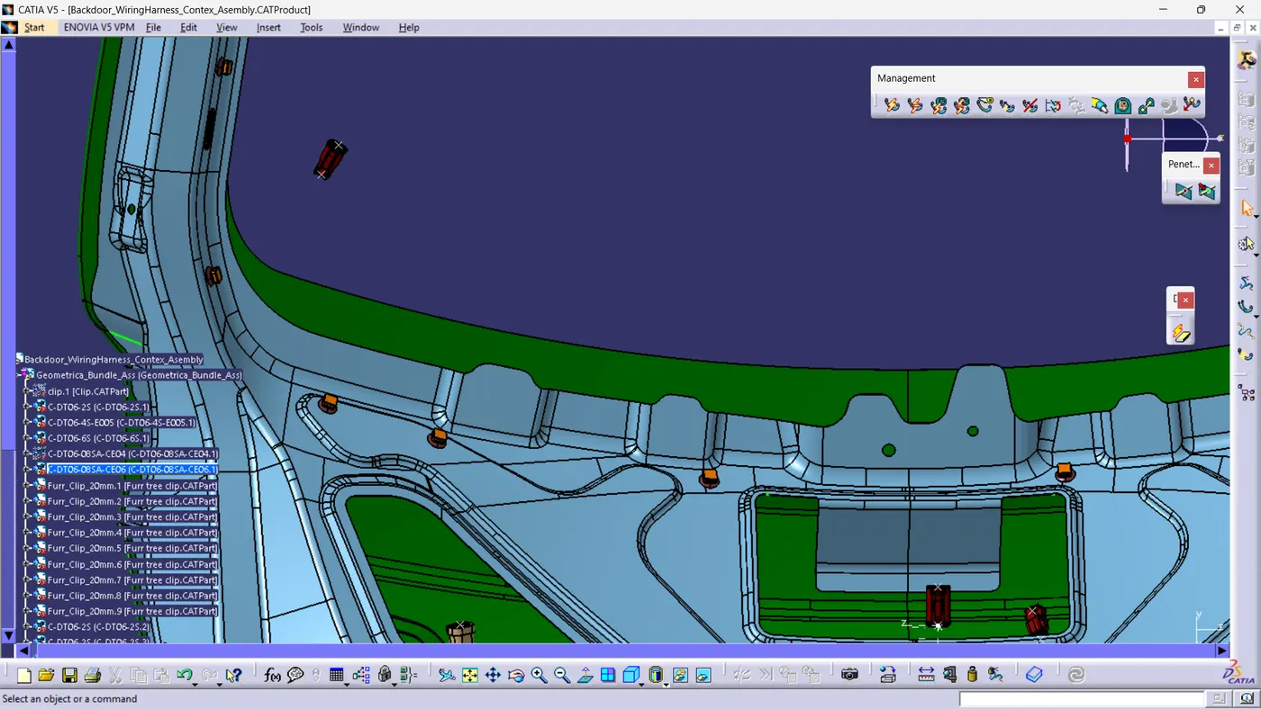
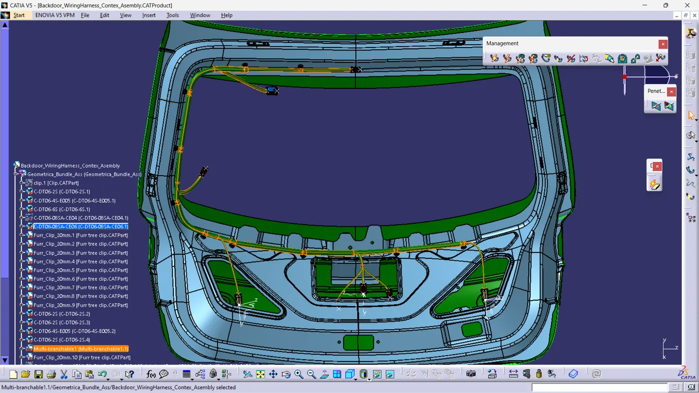
Step 5: Place All Clips at Require Place
Step 6: Wiring Harness Routing
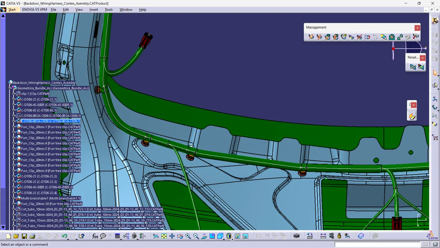
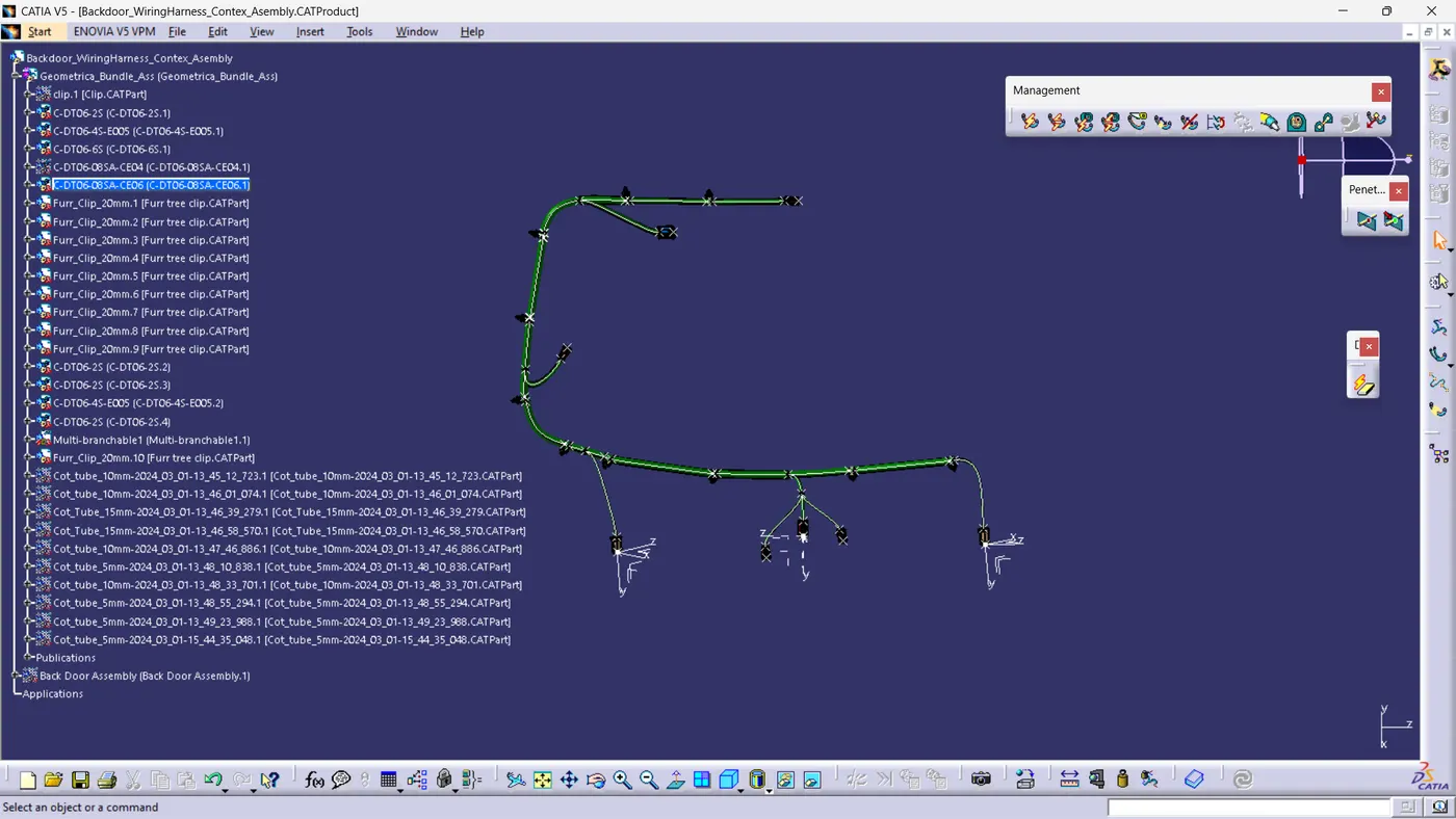
Final geometric bundle
Step 7: Applying protective cover
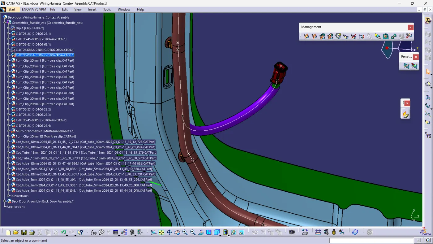
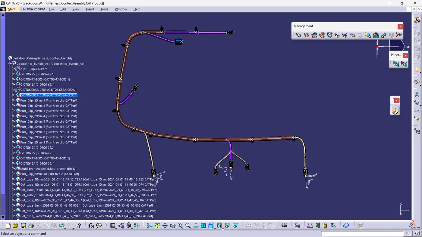
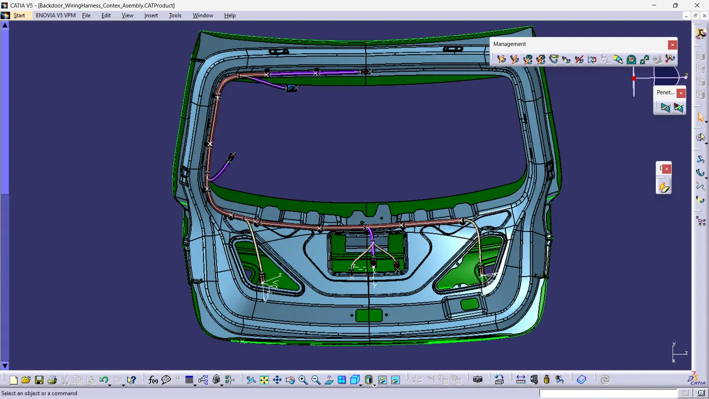
Step 8: Electrical Continuity Check
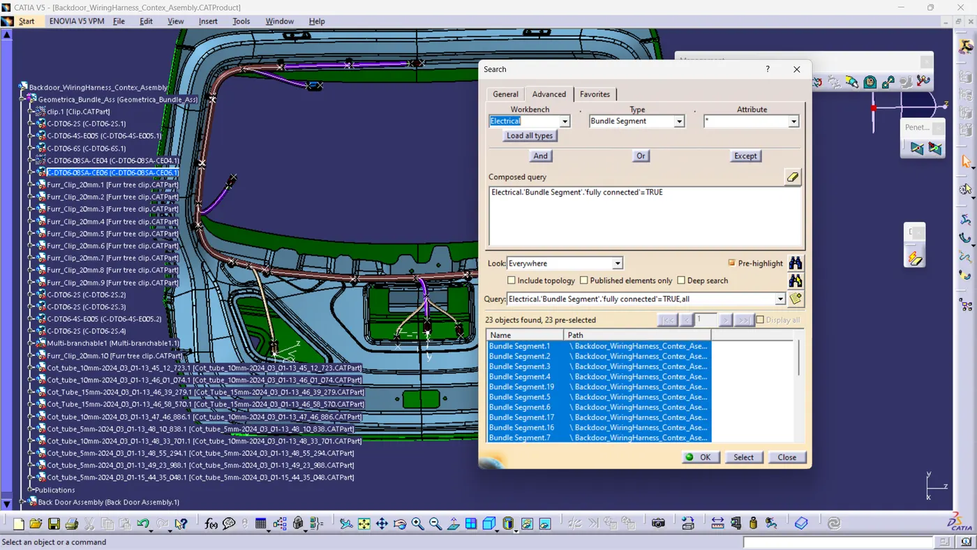
We need to ensure that the entire bundle is fully connected.
1 Go to edit and then click on search command.
2 Go to advanced
3 Select workbench as electrical, type as bundle segment and attribute as Fully connected
4 The select result should be as TRUE or FALSE and the click search to see the connectivity analysis result
Step 9 - WIRING HARNESS FLATTENING
conclusion: : In conclusion, the car back door wiring harness assembly has been completed following all packaging rules and industry standards. The harness was flattened and documented using CATIA V5, with all components correctly defined and protected. Proper routing and support with clips and clamps were also ensured.