Project 2
Quesions:-
Run simulations, change the threshold, create plots and measure current and hydrogen consumption. Specify the outputs. How to run the model.
Answers:-
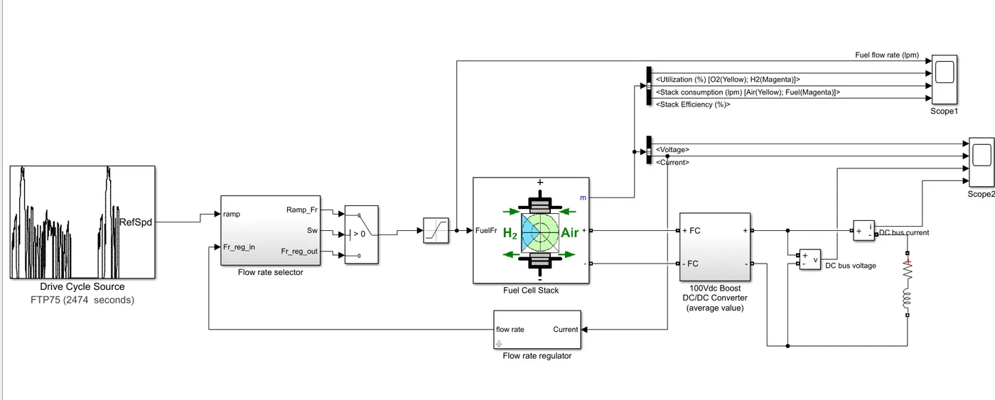
The model utilizes the drive cycle as its primary input. The flow rate selector integrates inputs from both the drive cycle and a flow rate regulator. It generates two outputs: the ramp signal and the actual flow rate. A switch within the fuel cell stack controls output based on predefined criteria. Motor specifications, nominal voltage, and operating condition efficiency are incorporated into the model. A boost converter steps up voltage and current, while voltage sensors measure these values. Additionally, an RLC circuit represents the system's load.
- Drive Cycle Input: The model takes a drive cycle profile as input. This could be represented as a time-series signal describing vehicle speed, acceleration, and other relevant parameters.
- Flow Rate Selector: This component decides the appropriate flow rate for the fuel cell stack based on inputs from two sources: the drive cycle and a flow rate regulator. The flow rate selector calculates the required hydrogen flow rate to meet the demand of the fuel cell stack.
- Ramp & Flow Rate Output: The flow rate selector outputs both the ramp signal (indicating the rate of change of the flow rate) and the actual flow rate to be supplied to the fuel cell stack.
- Switch (Fuel Cell Stack): This switch component controls the operation of the fuel cell stack based on predefined input criteria. It manages the flow of hydrogen to the stack based on the flow rate determined by the flow rate selector.
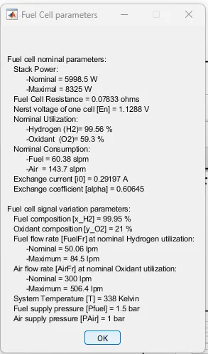
- Motor Specification & Nominal Voltage: The model incorporates motor specifications such as power rating, efficiency, and nominal voltage. These parameters are used to calculate the electrical load on the fuel cell stack.
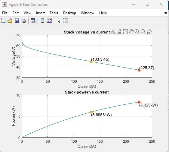
- Operating Condition Efficiency: Efficiency characteristics of the fuel cell stack under different operating conditions are provided. This information is crucial for accurately simulating the performance of the fuel cell system.
- Boost Converter: A boost converter is included in the model to step up the voltage and current output from the fuel cell stack to meet the requirements of the electric motor. The boost converter ensures compatibility between the fuel cell's output and the motor's input.
- Voltage Sensors: Voltage sensors are placed in the circuit to measure the output voltage of the fuel cell stack and the boost converter. These measurements are essential for monitoring the system's electrical parameters and ensuring proper operation.
- RLC Load Circuit: An RLC load circuit is connected to the output of the boost converter to represent the electrical load of the system. This load simulates the characteristics of the motor and other electrical components connected to the fuel cell system.
Resullts:-
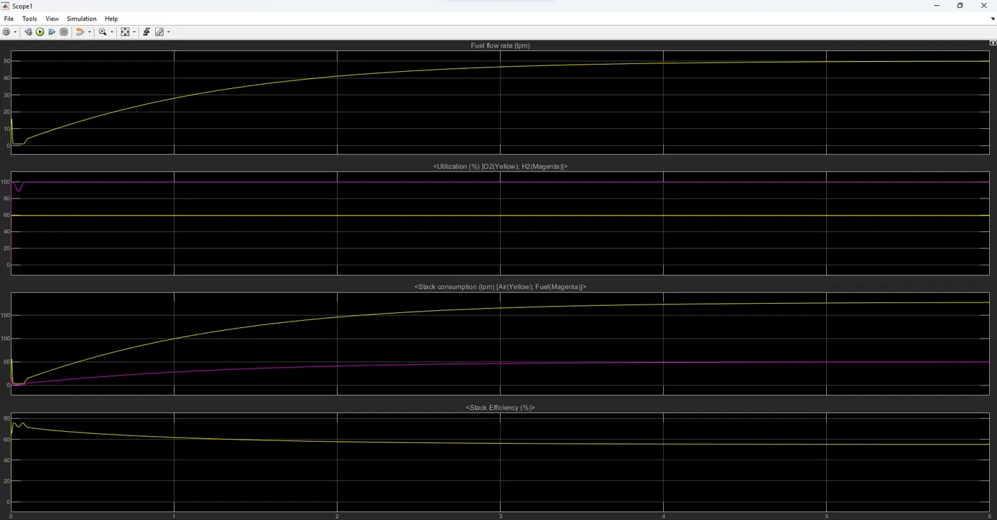
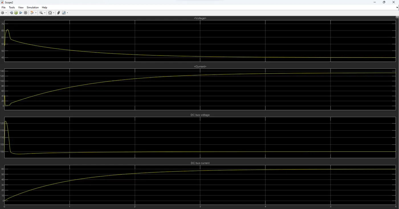
The fuel flow rate dynamically adjusts throughout the drive cycle, varying according to the vehicle's operational demands. The maximum value for the flow rate is capped at 80 units. Hydrogen (H2) utilization remains constant throughout the cycle. Initially, air utilization is high during vehicle startup. Both oxygen (O2) and hydrogen (H2) utilization start at 60%, but as the cycle progresses, the stack's consumption of air and fuel increases. At the beginning of the cycle, air consumption is approximately 150 liters per minute (lpm), while fuel consumption is around 50 lpm. During this initial phase, the stack efficiency decreases due to higher fuel consumption. However, as the cycle continues, the efficiency stabilizes and reaches approximately 40% towards the end of the cycle.