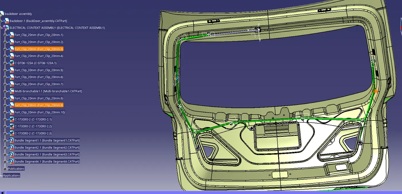
Project 2
objective:
Route the wiring harness on given car body and prepare flatten view drawing in catia v5. Application of all packaging rules, Industry best practices studided in this course shall be demonstrated in design. Apply protection coverings as required.
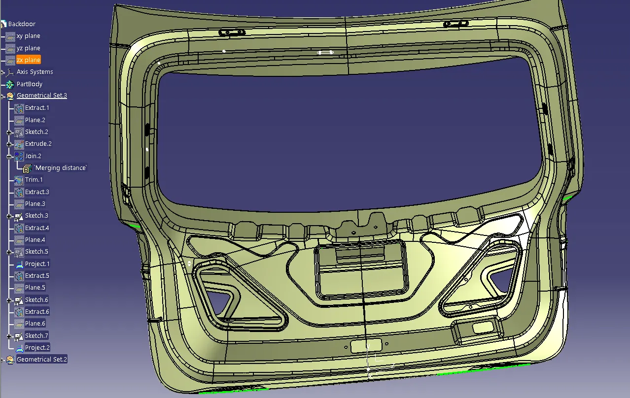
Step 1: Establishing Context Assembly:
We have developed a Context Assembly dedicated to the Backdoor Wire Harness, serving as the primary assembly depicted in the accompanying figure.
This Context Assembly will encompass data from the Backdoor Assembly and the Geometrical Bundle assembly of the Backdoor Wire Harness.
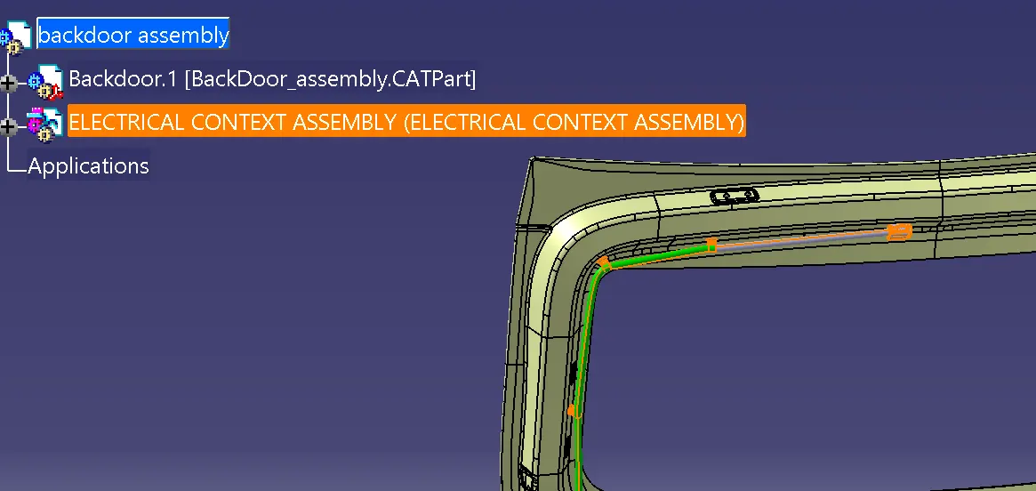
Step2:
Positioning the Connectors & Clip/ Clamps to the Back Door Assembly:
Here according to the requirment, We are Using:
1. C-DT06-12SA which is a 8 pole Connector Used as Inline Connector.
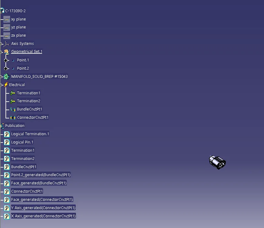
2. C-173090-2 Which is a 2 Pole Superseal Connector used for Numberplates Lighting and Power Latches.This Cad Data we obtained from te.com. To electrically define a connector , we must first define the geometrical parameters such as the Bundle Connection Point and the Connector Connection Point in the Electrical Part Design Workbench for the downloaded Connector.
connector 1(C-DT06-12SA)
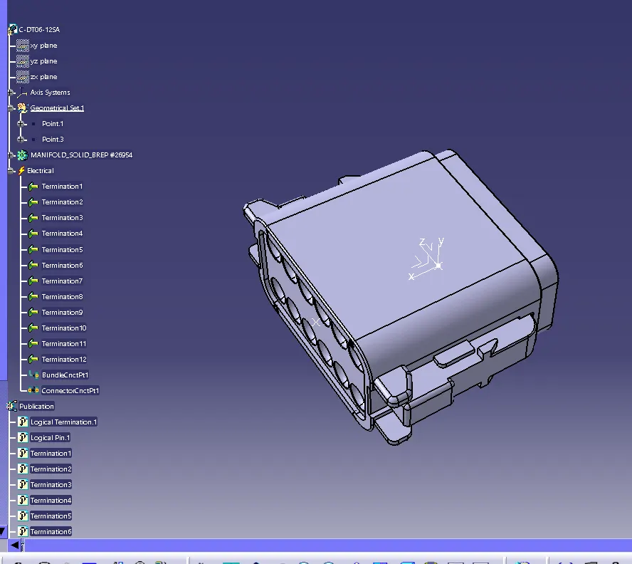
Connector 2(C-173090-2)
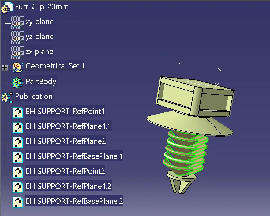
To ensure robust support, we employ Furr Tree Clips. Our task involves affixing these clips onto the backdoor, serving not only to bolster support but also to serve as a directional channel. To proceed, we must establish their electrical specifications alongside geometric parameters, outlining entry and exit points on both the left and right sides, as illustrated in the figure below.
Mounting the Furr Tree Clips and Placing the Connectors :
We have to Place the Connectors and Furr Tree Clips at Desired Position By Using the Smart Move , Snap & Manipulation Tools. We also use the Compass and smart move tool and manupulation tool is also used.
Step3: Bundle Routing From Interconnection:
. Here, We are routing the Bundle Segment from interconnection Connector to Furr Tree. The Diameter for this routing path is 10mm and bend radius ratio is assumed to be 1.5.
. We can See that the Bundle Segment is inside the Door Flange .
. We have to Route the Wire for Inline Connectors, Wiper motor Connector , Lighting Connector, Camera Connector, Sensor Connector.
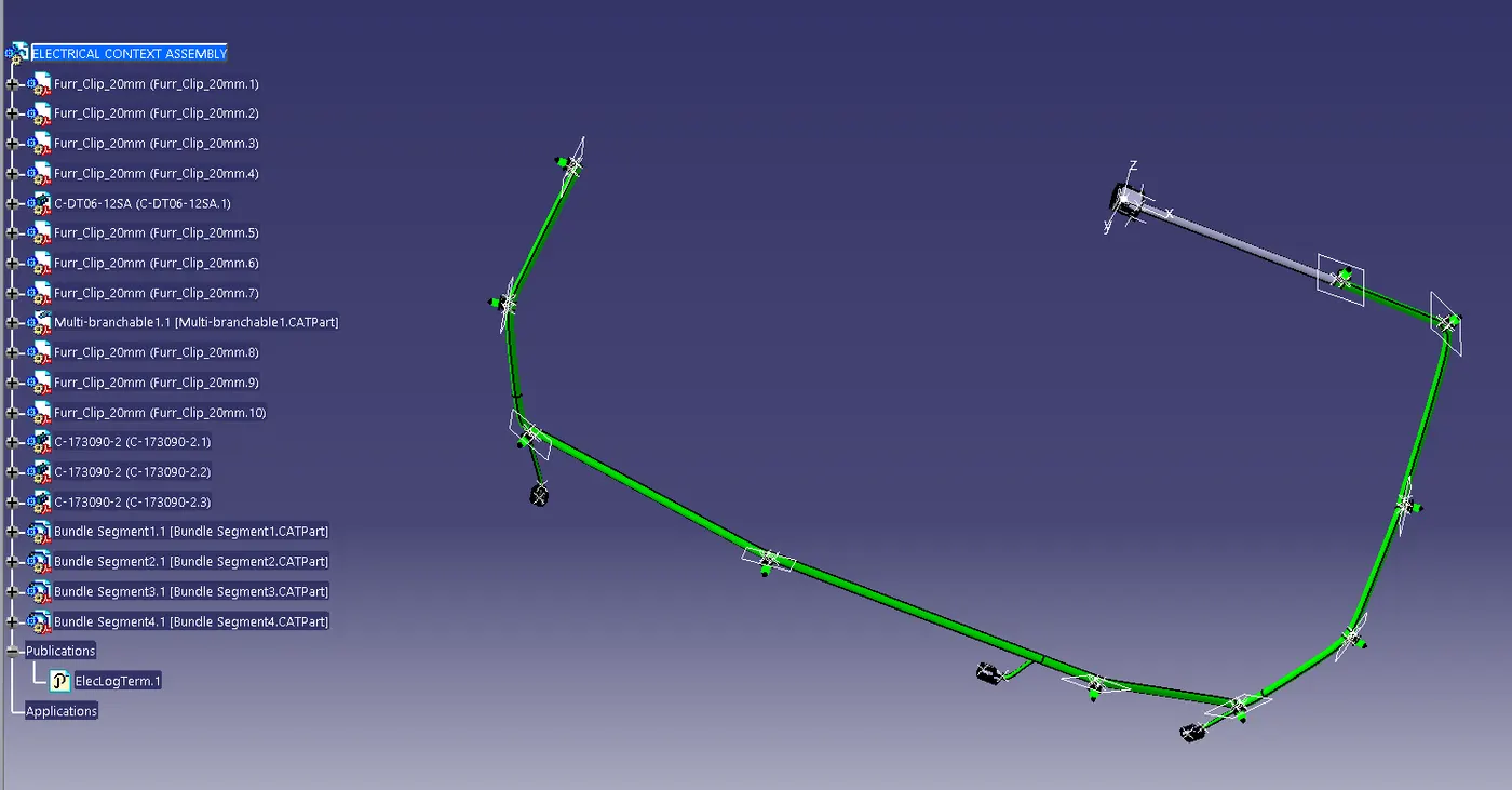
use protective covering to make the wiring harness look good and long lasting.
then we have to check for continuity in harness
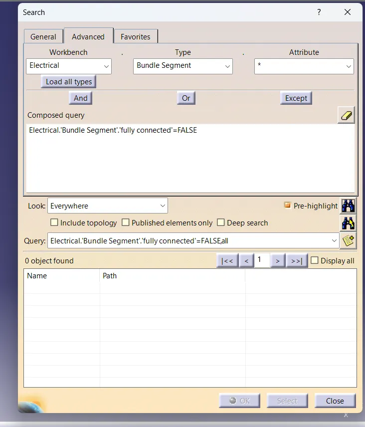
thus we can get our final context assembly