Project 2
1.ans: from the above given parms the values of the components have been calculated using the required formulas: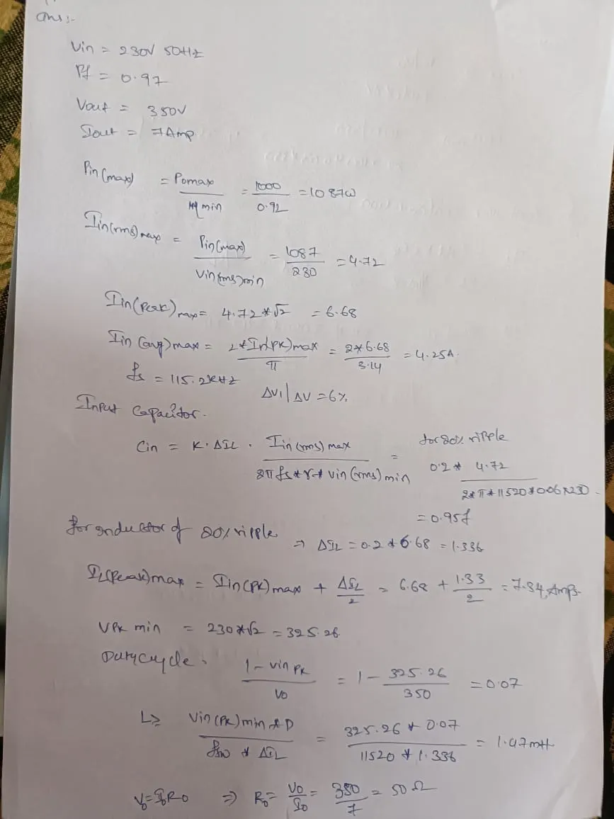
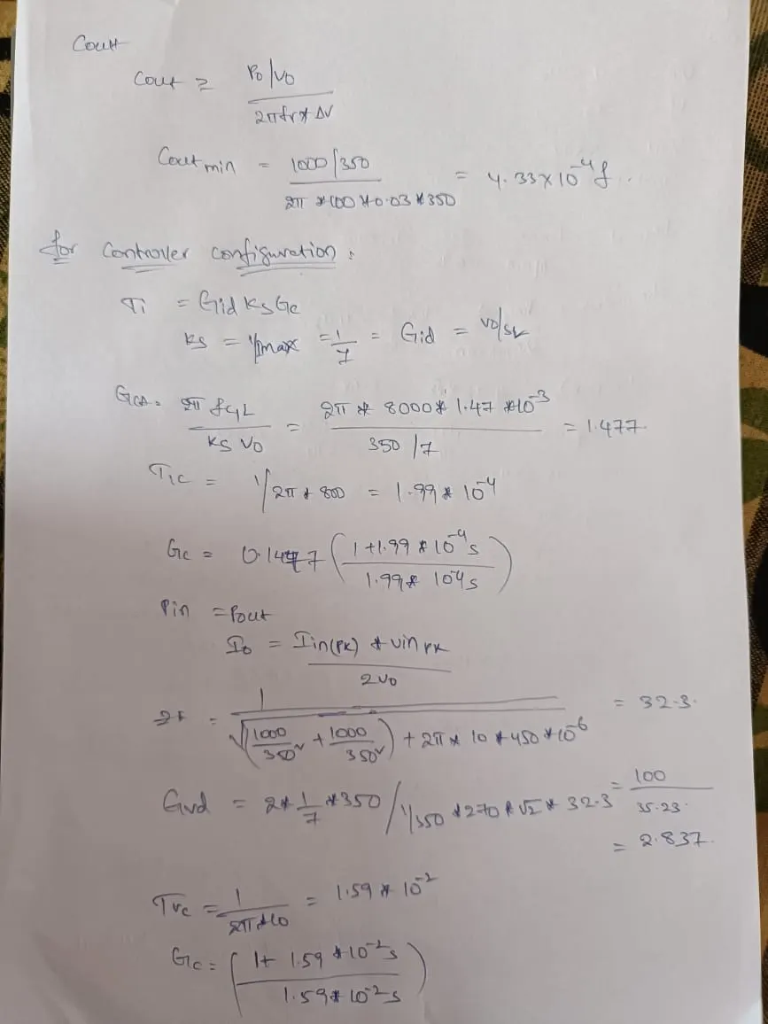
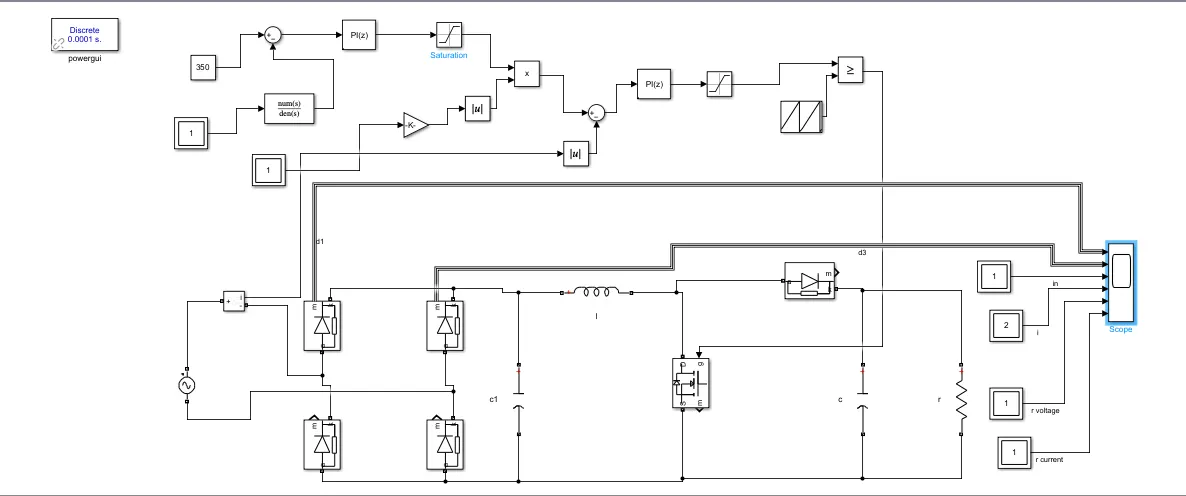
from the value obtained schematic is created using Matlab and output has been observed:
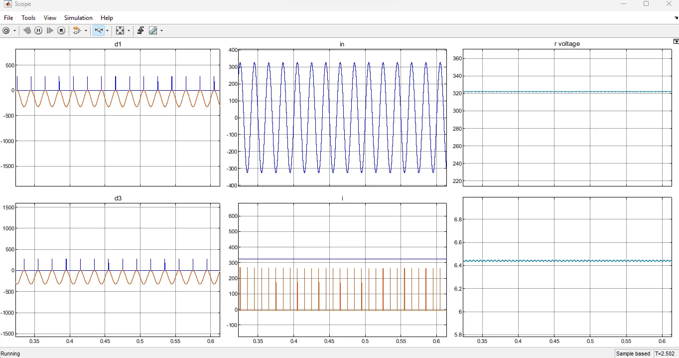
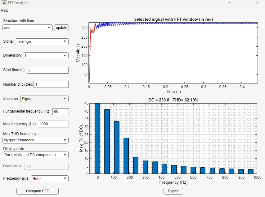
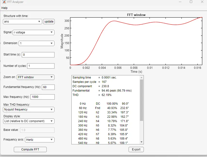
from the above waveforms thd and fft analysis is done to know the stability ods the system.
2. ans:
for the given high voltage system for simulation purpose, we can calculate the values of the load components according to the required voltage parms:
vin=11000 50 hz
vout=15000 v
i out= 10 amps
r= 1500 ohms
c= 0.75 micro farads
fom the basic parameters using the diode bridge rectifier for high volatge specs can be connected to the system along with boost converter can used to obtain the required voltage and current and we can observe the output voltage and analyse the system usinf fft tool.
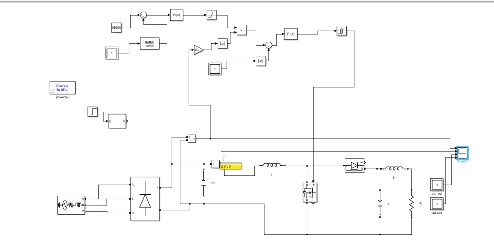
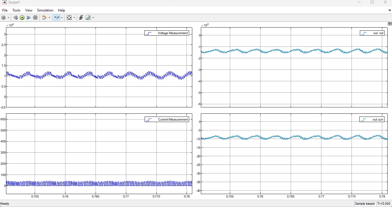
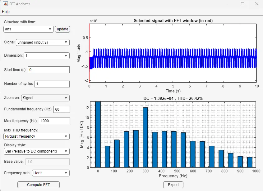
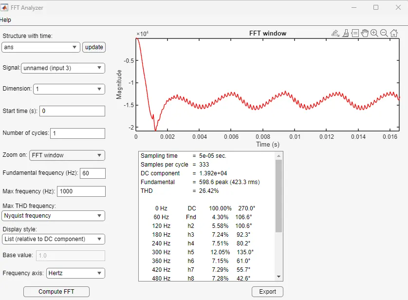
by using the feedback for the system we can achieve better output wrt to load according to given parms.