Project 2
AIM:
Route the Wiring Harness on given car BACKDOOR body and prepare flatten view drawing in Catia V5.
OBJECTIVE:
The objective of this project is to route the wiring harness and prepare flatten view drawing for the tailgate of the car. All types of packaging rules have to be considered while routing the harness and industry based practices shall be demonstrated in harness design. All necessary details like clearance, clipping/clamping selection, harness fixing requirements, harness continuity should be provided in order to design the wiring harness.
PROCEDURE:
STEP 01: CREATING CONTEXT ASSEMBLY:
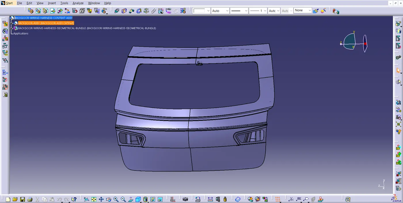
- We have created context assembly for the tail gate of the car as main assembly as shown in above figure.
- This context assembly contains the 3D cad data for the tail gate of the car and car tail gate harness geometrical bundle.
STEP 02: DEFINING CONNECTORS ELECTRICALLY:
Taking required components for the wire harness routing. Here we are using the components for backdoor upper and lower lights, wiper motor, sensors, and defogging equipment. The connectors used are first electrically defined and then added to the CATIA model.
The type of connectors used are given below :
1. Interconnection Connector:
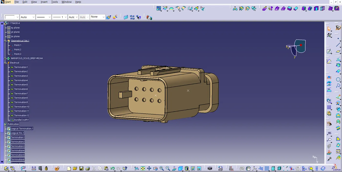
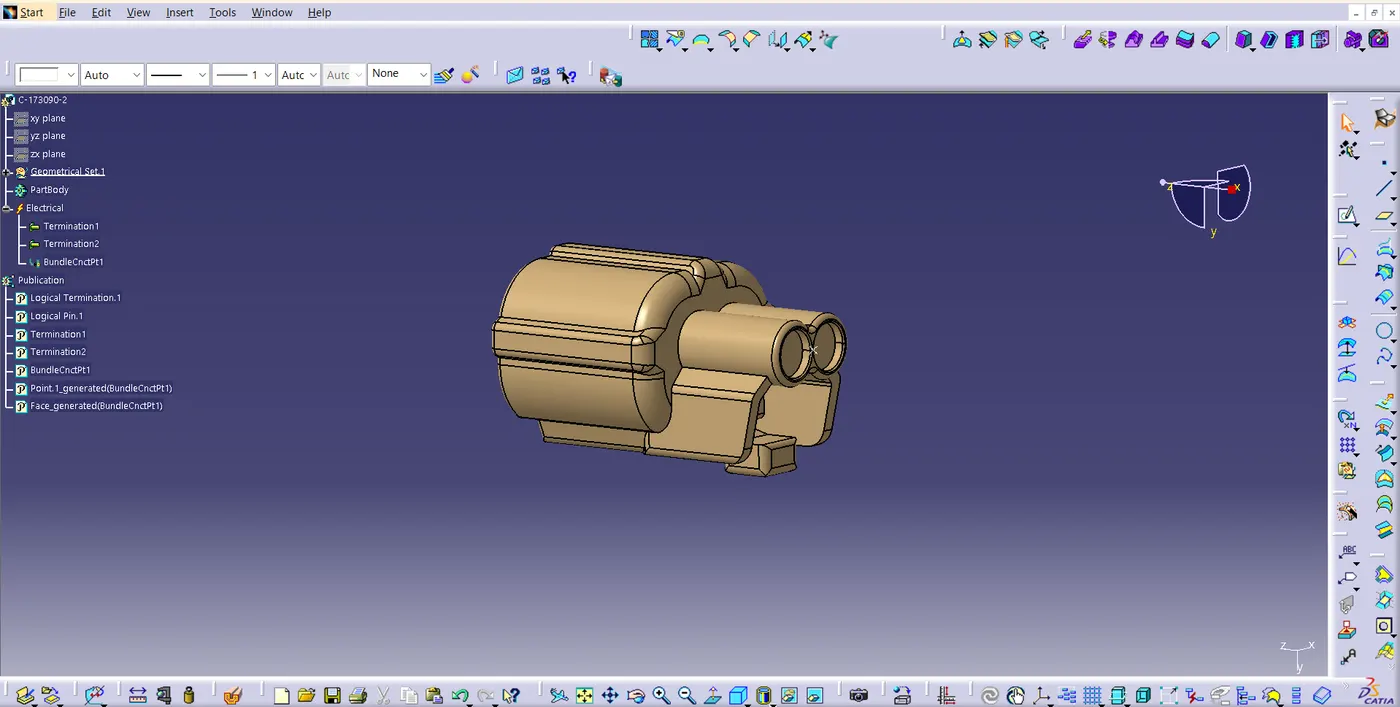
2. Two-pole connector used for light, sensors, and motors.
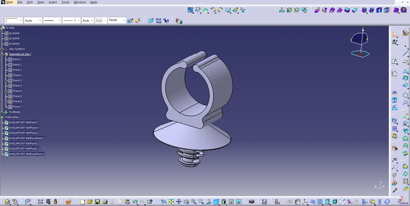
3. Clip and P-clamps are used to set the location of wire.
STEP 03: ADDING CONNECTORS AND NEEDED EQUIPMENTS:
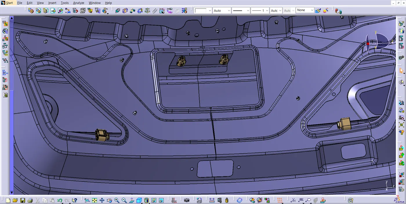
- The first part we position here is the interconnection connectors.
- Proper connectors are positioned for different electrical equipments.
- Place the firtree clips for the support in the needed positions.
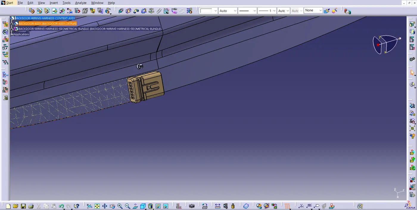
STEP 04 : BUNDLE ROUTING:
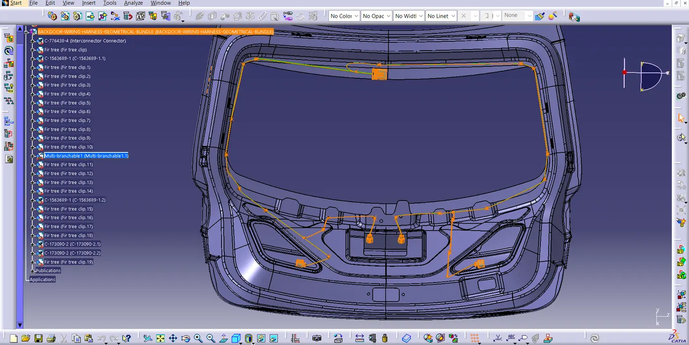
- The routing starts with interconnection connector placed on the Backdoor.
- It is continually routed to the following supports.
- The major routing supports used here are the firr tree clip.
- The back light connectors are routed.
- The connectors for the wiper motor equipment.
- The connectors for the number plate lights and the sensors.
STEP 05 : BUNDLE CONTINUITY CHECK:
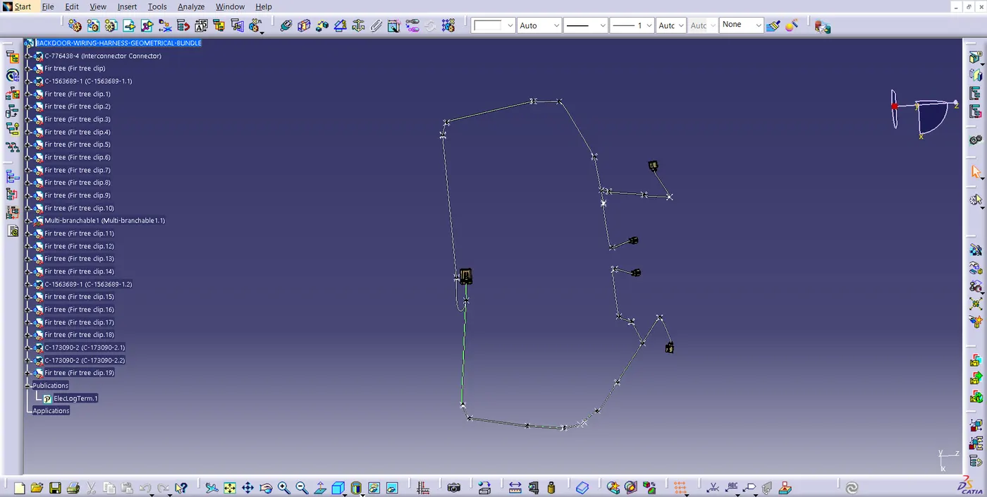
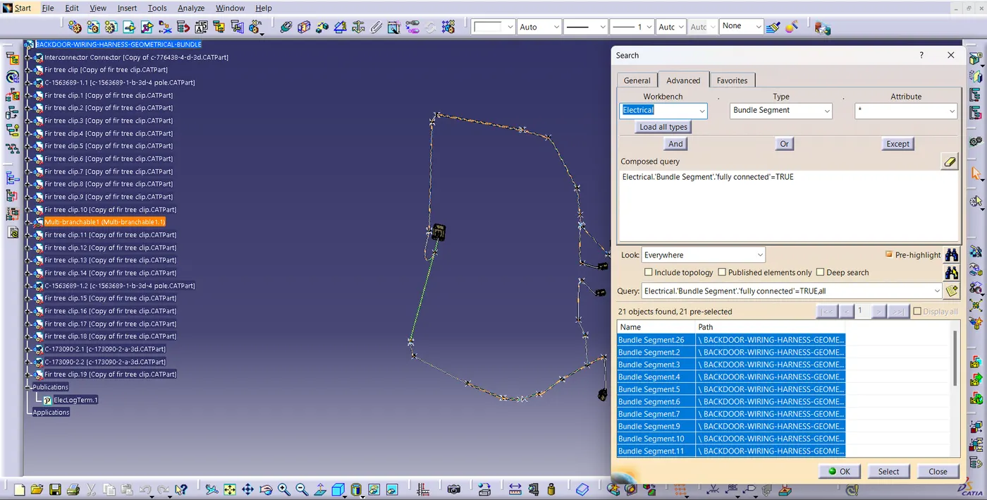
- Now we check the bundle continuity check for the further process.
- The continuity checked of TRUE and FALSE conditions.
STEP 06 : CREATE FLATTEN VIEW:
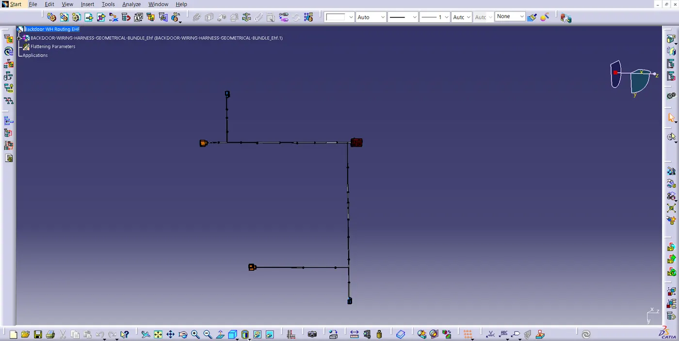
- To create a flatten view of the harness assembly, we have to work in Electrical Harness Flattening workbench in Catia V5.
- Also, we have to make sure that the flattening file is saved into the same folder where we have all the parts of the harness assembly.
- After that, we have to extract and bring the bundle assembly into the car tail gate flattening product file.
- To flatten the harness assembly, we have selected Face as an active plane and selected all the branches.
- Now, we have a flatten view of the wiring harness geometrical bundle assembly.
- After creating flatten view, we have to rotate the connectors and clips in right direction along the selected plane using manipulation tool.
STEP 07: Creating a Flatten view Drawing for the Wiring Harness Assembly :
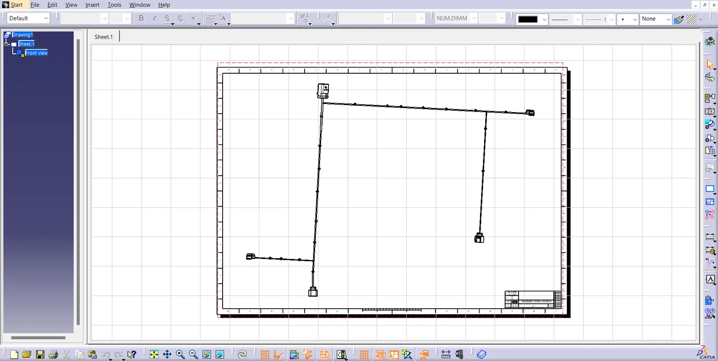
- we have to make new drawing file and define all the necessary drawing parameter.
- we have to insert front view of the harness assembly into drawing file and define drawing properties.
- It should be noted that for the Dress-up feature 3D wireframe is always ON. If this setting is not selected then the bundle segments will not be visible on the drawing view.
CONCLUSION:
Routing of the wiring harness for the Backdoor assembly has been successfully done and prepared flatten view drawing in CATIA V5 as per the design requirements.