Project 2
WIRING HARNESS ROUTING AND FLATTENING ON THE BACK DOOR
Aim:
The project aims to route the wiring harness on the given backdoor of a car and prepare a flattened view drawing in the CATIA V5 by applying all packaging rules and following the industry standards and Design guidelines.
Introduction:
Wiring Harness Design and Routing:
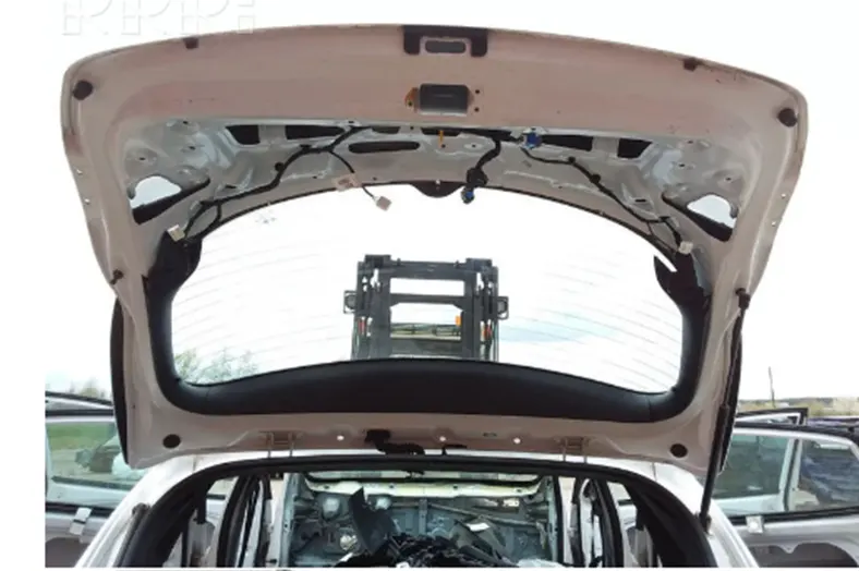
Wiring harness are a mixture of wires that are bundled together to form a wire harness.Wire harnes range in complexity from a few individual wires going point to point to hundreds of individual wires,multi conductor cables and welded wires all forming a complex wire harness used to transmit power and all types of data.Wire harness designs are highly customizable.They may need to be concealed behind walls,fit within electrical boxes or conform to other space constraints.
A Wiring harness Routing structure includes a wiring harness routing member configured to be attached to a vehicle body and a protector that accommodates and holds a wiring harness.The protector has a recess shape in ehich the protector is opened in one direction in a sectional view.Atleast one of the wiring harness routing members and the protector includes a fixing mechanisms that fixes the protector to the wiring harness routing member.The protector and the wiring harness routing member are configured to be integrated via the fixing mechanism.
Wiring Harness Flattening:
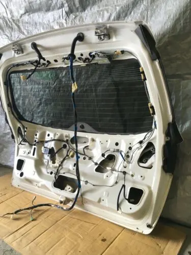
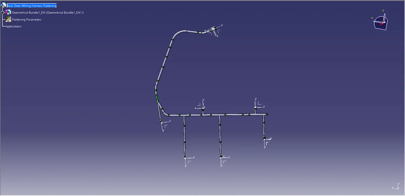
Electrical Harness Flattening operations is used foe converting the 3D format of the wiring harness geometrical bundle into associated 2D drawings,Which will be taken as refernece during the various stages of manufacturing,assembling,installation and servicing of wiring harness.
Once a product is ready to manufacure,its design must be precise or its risks costly errors and delays.Collaboration is the essential key to successful documentation and design between harness designers and manufacturing.CATIA-Electrical wire harness Flattening provides automatic and complte ftattening of 3D Electtrical harnesses for manufacturing documentation in a concurrent engineering environment.
Design Methodologies:
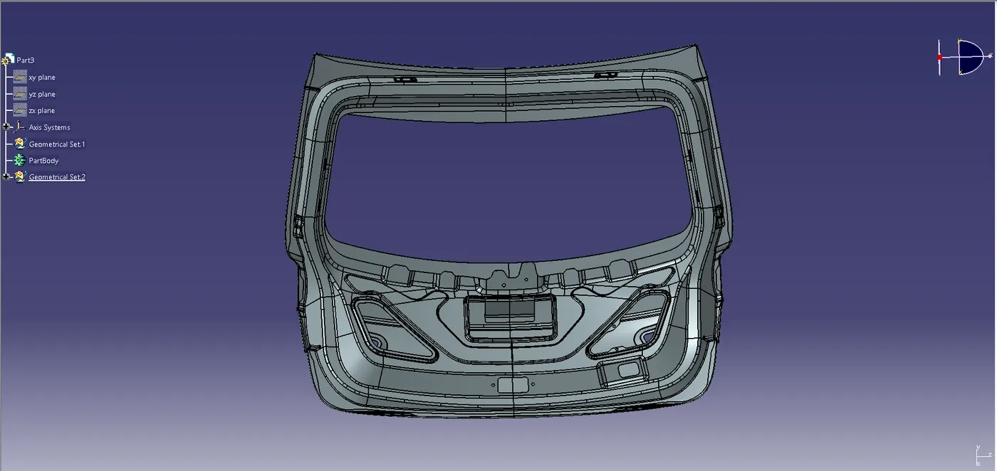
- Open the CAD File of the Back Door and identify the position of electrical components such as tail lights,Wiper motor mounting area etc where the wiring harness routing is to be done.
- Decide the type of connectors,Clamps,supports and external components going to be used for the back Door Routing.
- Understand The concept path of the main branch of the bundle that is going to be connected with the electrical parts of the backdoor.
Define all the Connectors as Electrical Product:
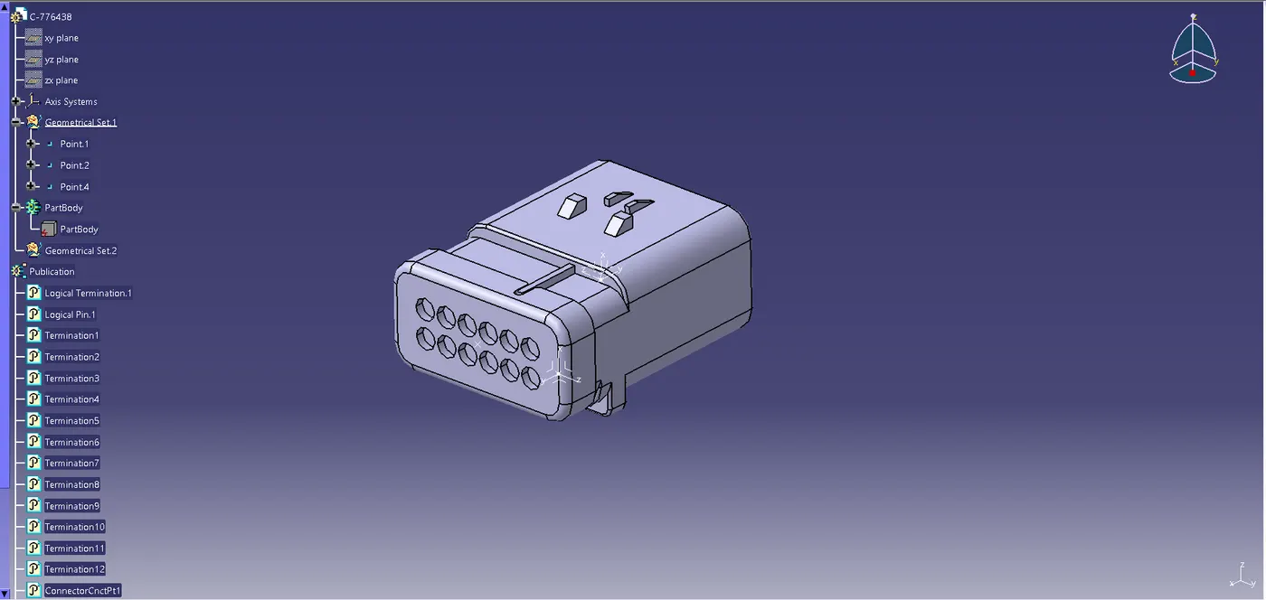
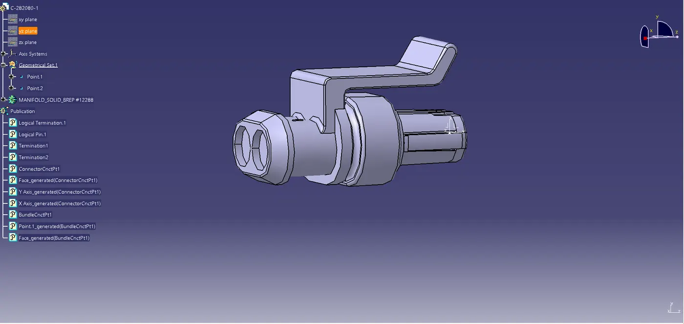
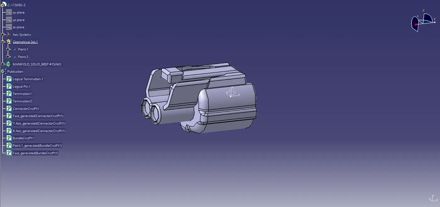
- Download the CAd Data File of the connectors from the given source and open it in the CATIA part workbench.
- Indentify the faces of the connector connection point,bundle connection point and the mechanically locking sides of the connectors.
- Create the grometries like center points of the connector connection point and bundle connection point by selecting appropriate edges and create an axis on the Connector connection point by placing the Y axis towards the connector connection point direction and the X axis pointing towards the sides of the locking mechanism.The same axis direction should be followed for the compatible mating part.
- Now switch to the electrical part design workbench and define the model as an electrical connector part by using the define Connector command.
- Define the connector connection point by giving the representation as the back connector connector connection point,selecting the face of contact,coincidence direction as Y axis and orientation direction as X axis.
- By using the Define bundle connection point command select the face of the bundle side and the bundle center point to define the bundle connection point of the connector.
- Now the connector part file is converted into electrical file with all the electrical properties.
- Follow the same steps for converting all the connectors into electrical.
Define The Fir Tree Clips Electrically:
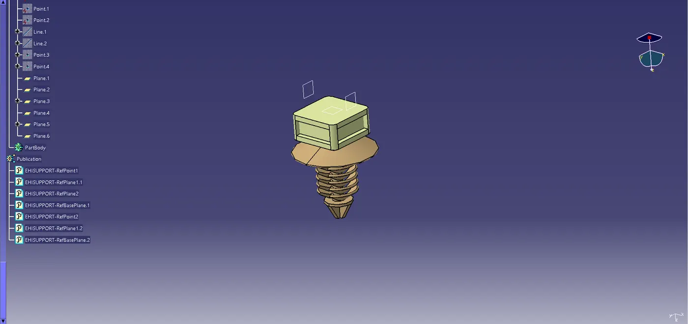
- Study the Fir tree Clips model and understand how the bundle is passed through it identify the emtry,exit,base and mechanically connected faces.
- Fir tree clips are bidirectinal components and we have to define the points and planes alond three parameters,entry face,exit face and base face.
- Switch to the electrical part design part design workbench and define the fir tree model as an electrical support by using the define support part command.
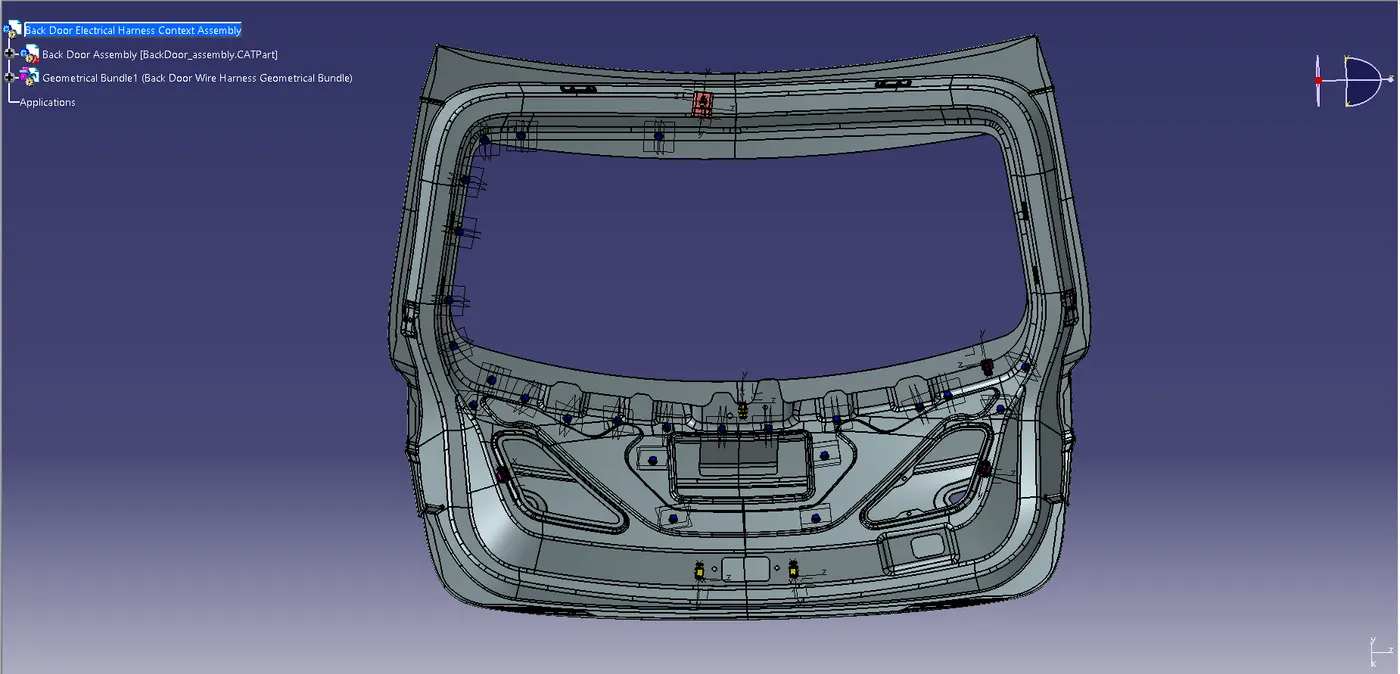
Create a New product file for the wiring Harness Assembly context,Adding relevant components to each product file and covert the geometical bundle assembly file into an electrical bundle:
- The main Product file for the wiring harness assembly context is opened and add the new product file for the geometrical bundle assembly under it.
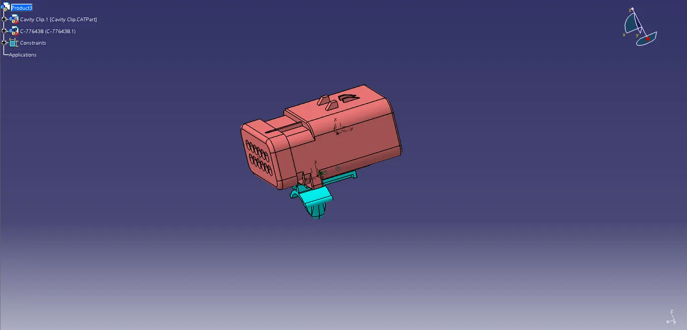
- Open the geometrical bundle assembly in a new window and switch to the mechanical assembly workbench and add all the relevant connectors,fir tree clips etc requried for the harness assembly routing.
- Position the connectors and other components to the desired location by using various commands available in the mechanical assembly workbench.
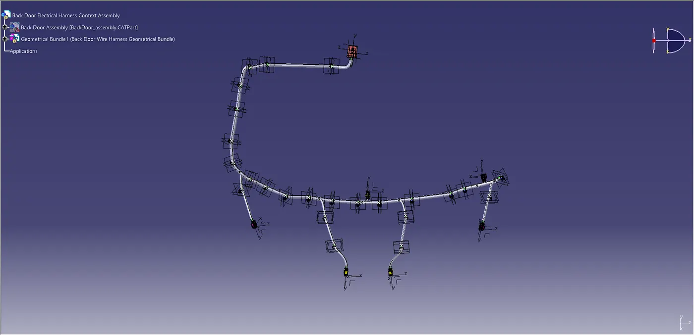
- Switch to the elctrical harness assembly workbench and activate the geometrical bundle command and select the geometrical bundle assembly file from the tree structure then it will convert the geometrical bundle assembly file into an electrical assembly file.
Routing The Wiring Harness Assembly:
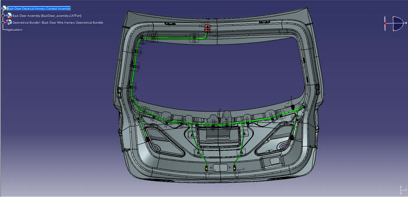
- By using the multi branchable document command available in the electrical harness assembly workbench and adjust the options available likes,connector diameter,bend radius ratia,build mode,and with the help of routing objects options define the routing by adding the desired electrically defined components and adjust the tangency if requried to get the proper bundle connection between Connectors.
- It is always recommened to use multi branch routing during the wiring harness assembly.
- We can add branches or split the existing branches by double-clicking the multi branchable command then it will automatically switch into the wiring harness installation workbench from there we can add the a branch point on the existing bundle to the requried position.
- Again go the multi branchable document and select the apppropriate electrically defined components and bundles to create sub branches in the assembly.
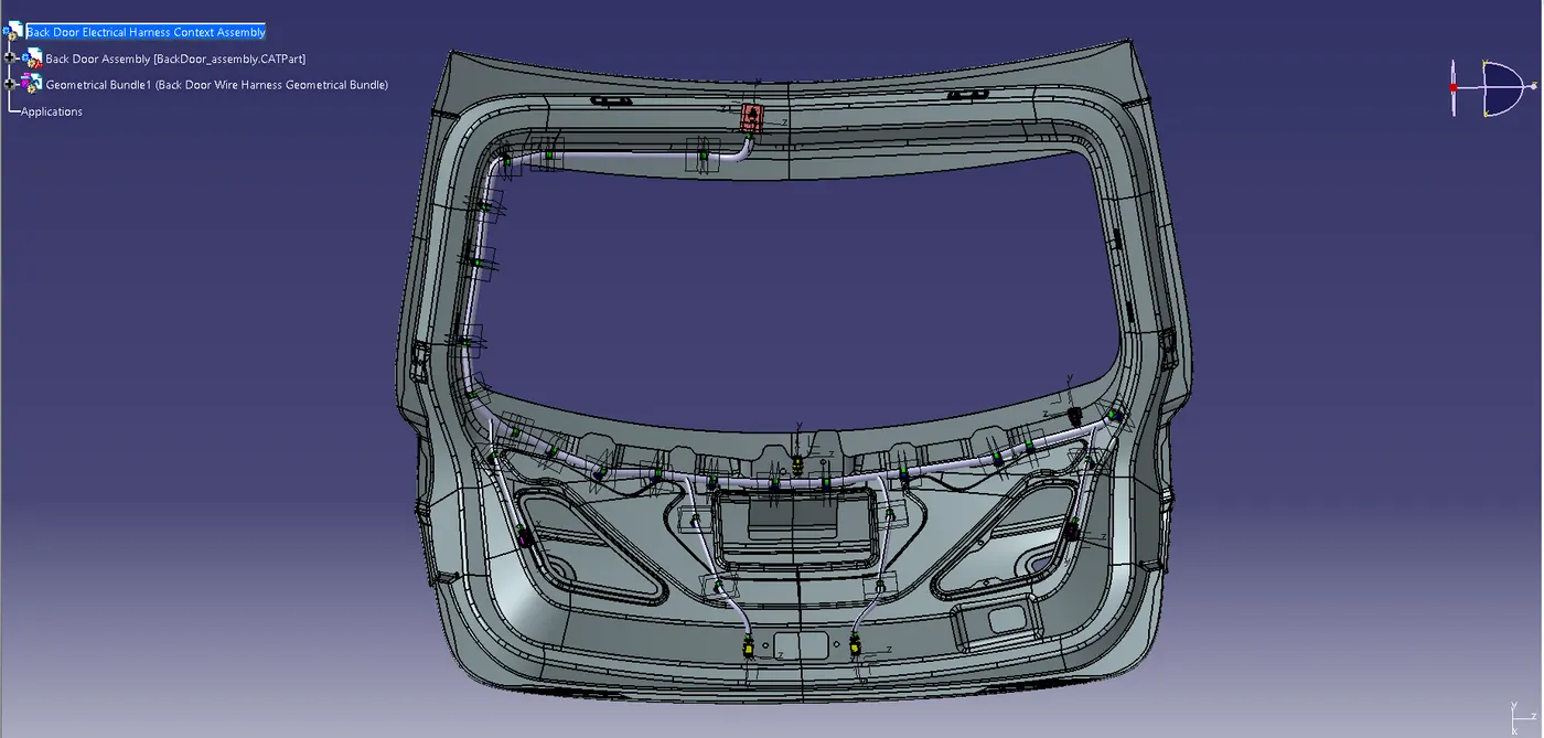
Adding Protective Covering To The Bundles:
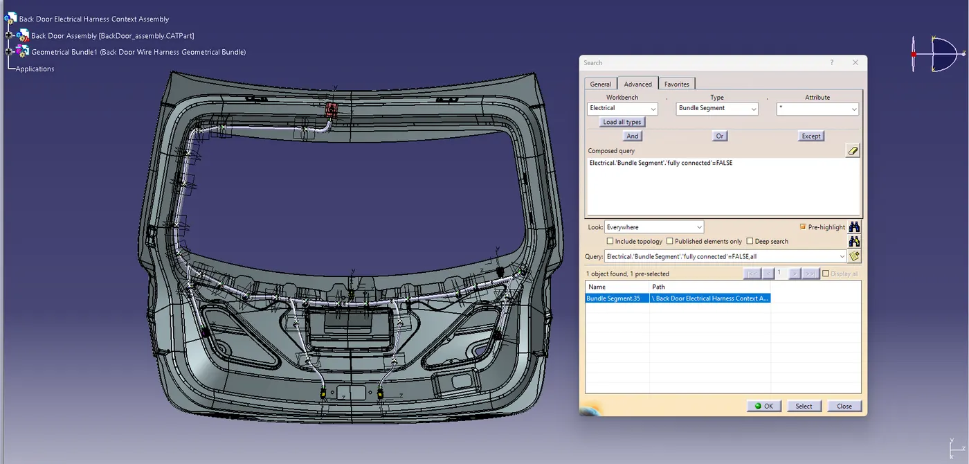
Check For The Bundle Continuity And Bundle Warnings In the Wiring Harness Assembly:
Create a New Product File for Wiring Harness Flattening,Initial Settings and Adding the relevant Components:
Now we need to flatten the routing using the commands.
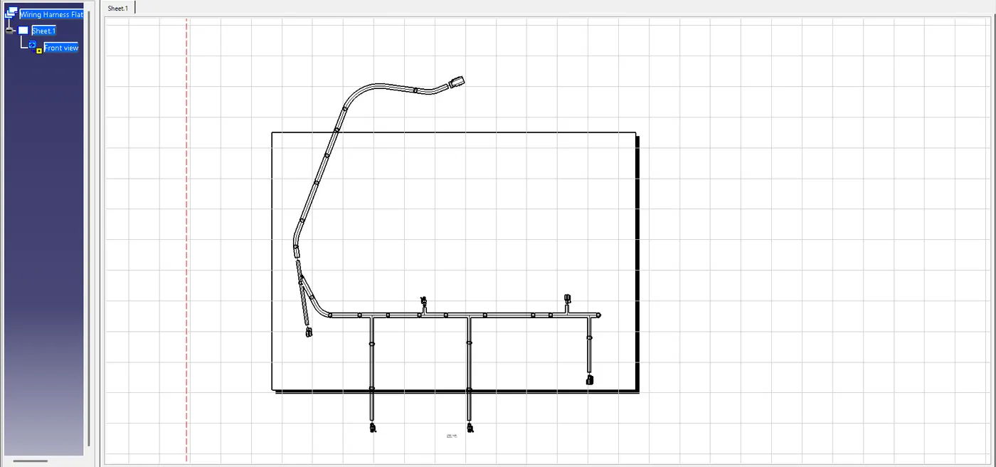
 After wire Bundle is flattened in the respective product file and workbench can be represented in the drawing sheet.
Representation Of The Flattened Wire In The Drawing Sheet:
Conclusion:
From the above Description we learnt how to route wire harness on a back door.we also learnt about different packaging rules that must be kept in mind during wire routing and we also learnt how to flatten the and represent it in the drawing sheet.
https://drive.google.com/file/d/16r4rioysZ_9n2_Sp9EJymL7YqRMeJMsg/view?usp=sharing
https://drive.google.com/file/d/1PaE8QUNt7brvHjFHdeuVzcF8_tG6y802/view?usp=sharing